MITSUBISHI MONTERO 1987 1.G Workshop Manual
Manufacturer: MITSUBISHI, Model Year: 1987, Model line: MONTERO, Model: MITSUBISHI MONTERO 1987 1.GPages: 284, PDF Size: 14.74 MB
Page 111 of 284
STARTING SYSTEM-General Information 8-91
STARTING SYSTEM
GENERAL INFORMATION
NOBFAAJ
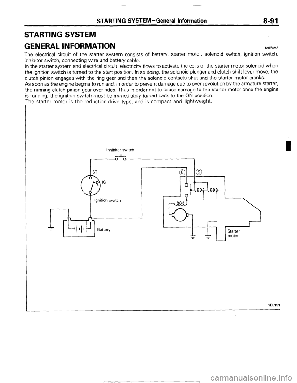
The electrical circuit of the starter system consists of battery, starter motor, solenoid switch, ignition switch,
inhibitor switch, connecting wire and battery cable.
In the starter system and electrical circuit, electricity flows to activate the coils of the starter motor solenoid when
the ignition switch is turned to the start position. In so doing, the solenoid plunger and clutch shift lever move, the
clutch pinion engages with the ring gear and then the solenoid contacts shut and the starter motor cranks.
As soon as the engine begins to run and, in order to prevent damage due to over-revolution by the armature starter,
the running clutch pinion gear over-rides, Thus in order not to cause damage to the starter motor once the engine
is running, the ignition switch must be immediately turned back to the ON position.
The starter motor is the reduction-drive type, and is compact and lightweight.
Inhibiter switch
-
I lEL151
1 STB Revision
Page 112 of 284
8-92 STARTING SYSTEM - General Information
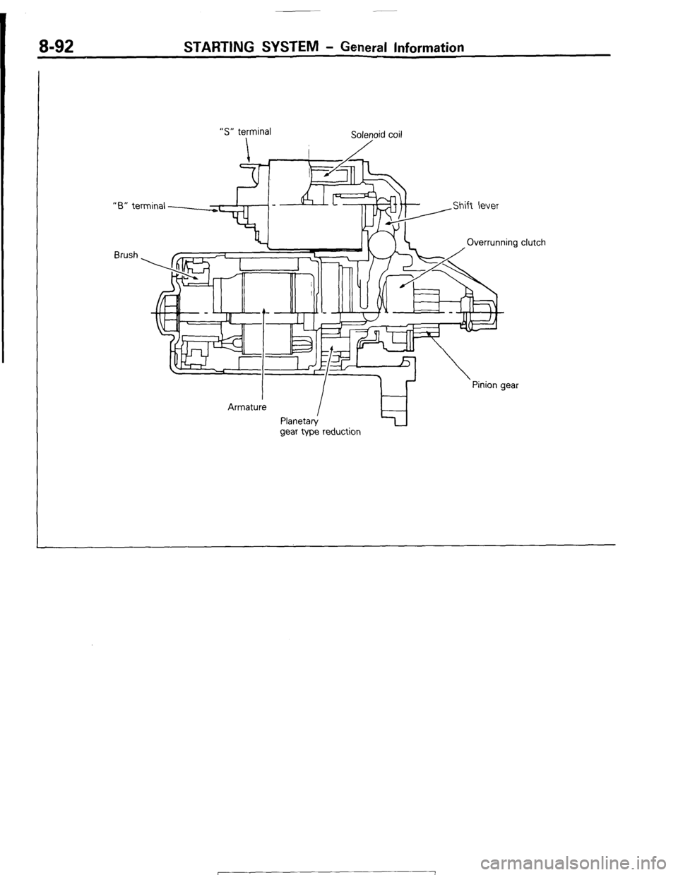
“S” terminal
Sole;oid coil
“6” terminal -
clutch
Brush
gear type reduction
1 ST6 Revision
Page 113 of 284
SPECIFICATIONS
STARTING SYSTEM - Specifications 8-93
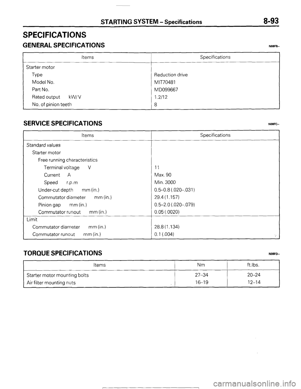
GENERAL SPECIFICATIONS NOIFB-
Items
Starter motor
Type
Model No.
Part No.
Rated output kW1 v
No. of pinion teeth Specifications
Reduction drive
MIT70481
M DO99667
I.2112
8
SERVICE SPECIFICATIONS
Items
Standard values
Starter motor
Free running characteristics
Terminal voltage V
Current A
Speed r.p.m
Under-cut depth mm (in.)
Commutator diameter mm (in.)
Pinion gap mm (in.)
Commutator runout mm (in.)
Limit
Commutator diameter mm (in.)
Commutator runout mm (in.) Specifications
11
Max. 90
Min. 3000
0.5-0.8(.020-,031)
29.4(1.157)
0.5-2.0(.020-,079)
0.05(.0020)
28.8(1.134)
0.1 (.004)
'_'
TORQUE SPECIFICATIONS
Items Nm ftlbs.
Starter motor mounting bolts 27-34 20-24
Air filter mounting nuts 16-19
12-14
1 STB Revision
Page 114 of 284
8-94 STARTING SYSTEM -Troubleshooting
TROUBLESHOOTING NOFH-
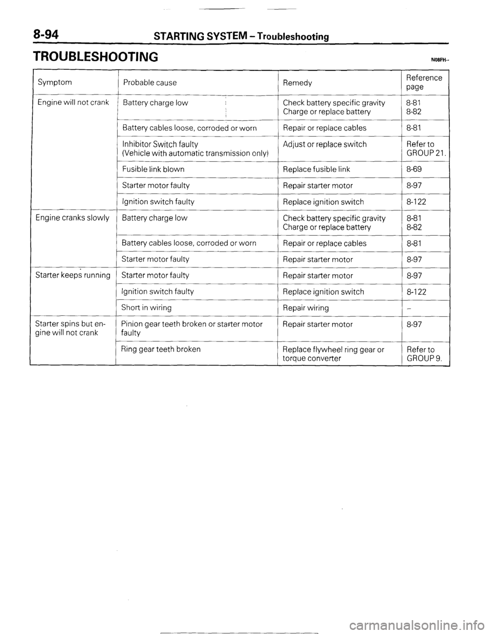
Symptom
Engine will not crank
Engine cranks slowly
Starter keeps running
Starter spins but en-
Jine will not crank Probable cause Remedy Reference
paw
Battery charge low Check battery specific gravity 8-81
,
I Charge or replace battery 8-82
Battery cables loose, corroded or worn Repair or replace cables 8-81
__~
Inhibitor Switch faulty Adjust or replace switch Refer to
(Vehicle with automatic transmission only) GROUP 21.
Fusible link blown
Replace fusible link 8-69
Starter motor faulty
Repair starter motor 8-97
Ignition switch faulty Replace ignition switch 8-l 22
Battery charge low Check battery specific gravity 8-8 1
Charge or replace battery 8-82
Battery cables loose, corroded or worn
Repair or replace cables 8-8 1
Starter motor faulty Repair starter motor 8-97
Starter motor faulty Repair starter motor 8-97
Ignition switch faulty
Replace ignition switch 8-l 22
I
Short in wiring
Repair wiring -
Pinion gear teeth broken or starter motor Repair starter motor 8-97
faulty
Ring gear teeth broken Replace flywheel ring gear or Refer to
torque converter GROUP 9.
1 STB Revision
-7
Page 115 of 284
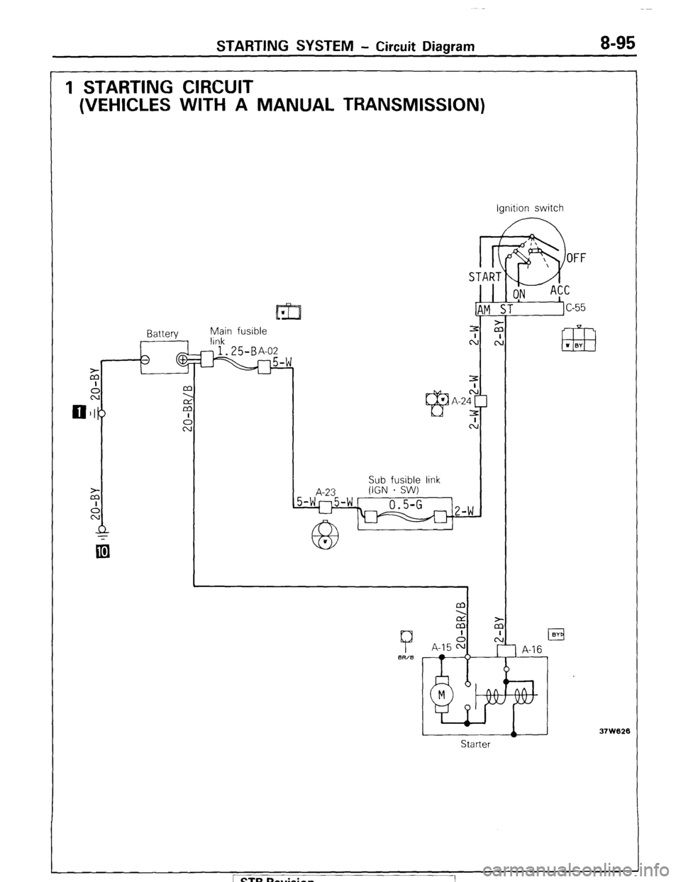
STARTING SYSTEM - Circuit Diagram 8-95
1 STARTING CIRCUIT
(VEHICLES WITH A MANUAL TRANSMISSION)
11171 w
$in fusible
START
I k
9
OFF
ON ACC
ST
c-55
.I
m I BY
Sub fusible link Ignition switch
Starter
37W626 / STB Revision
Page 116 of 284
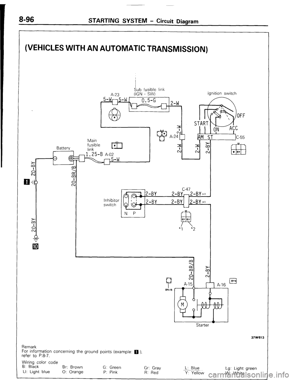
8-96 STARTING SYSTEM - Circuit Diagram
(VEHICLES WITH AN AUTOMATIC TRANSMISSION)
I
Sub fusible link
A-23 (IGN . SW)
_ 5-WI-754 1
0.5-G 1, 1,
L-l m 1 L-W
Battery Ignition switch
c-47
2-BY-Z-BY*2
N P
!-BY Z-BY1 (Z-BY*]
L-l
R BY BY
“I “2
Remark
For information concerning the ground points (example:
q ),
refer to P.8-7.
Wiring color code
B: Black
Br: Brown
G: Green
Gr: Gray L: Blue
LI: Light blue
0: Orange P: Pink Lg: Light green
R: Red
Y: Yellow
W: White
STB Revision
Page 117 of 284
STARTING WSTEM - Starter Motor 8-97
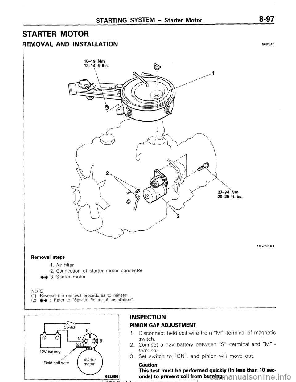
STARTER MOTOR
REMOVAL AND INSTALLATION NOBFJAE
16-19 Nm 16-19 Nm
12-l? ft.lbs. 12-14 ft.lbs.
15W1564
Removal steps
1. Air filter
2. Connection of starter motor connector
l * 3. Starter motor
NOTE
(1) Reverse the removal procedures to reinstall.
(2) ++ : Refer to “Service Points of Installation”
6EL05( This test must be performed quickly (in less than 10 sec-
onds) to prevent coil from burning. D Revision
INSPECTION PINION GAP ADJUSTMENT
I, Disconnect field coil wire from “M” -terminal of magnetic
switch.
2. Connect a 12V battery between “S” -terminal and “M” -
terminal.
3. Set switch to “ON”, and pinion will move out.
Caution
Page 118 of 284
8-98 STARTING SYSTEM -Starter Motor
Pinion
6EL003
lEL113
/ Field coil wire
Field coil wire
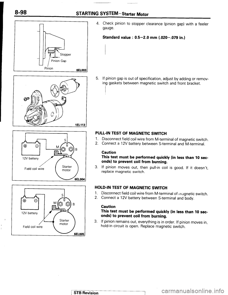
4. Check pinion to stopper clearance (pinion gap) with a feeler
gauge.
Standard value : 0.5-2.0 mm (.020-.079 in.)
5. If pinion gap is out of specification, adjust by adding or remov-
ing gaskets between magnetic switch and front bracket.
PULL-IN TEST OF MAGNETIC SWITCH
1. Disconnect field coil wire from M-terminal of magnetic switch.
2. Connect a 12V battery between S-terminal and M-terminal.
Caution
This test must be performed quickly (in less than 10 sec-
onds) to prevent coil from burning.
3. If pinion moves out, then pull-in coil is good. If it doesn’t,
replace magnetic switch.
HOLD-IN TEST OF MAGNETIC SWITCH
1.
2. Disconnect field coil wire from M-terminal of in;ignetic switch.
Connect a 12V battery between S-terminal and body.
Caution
This test must be performed quickly (in less than 10 sec-
onds) to prevent coil from burning.
3. If pinion remains out, everything is in order. If pinion moves in,
hold-in circuit is open. Replace magnetic switch.
1 ST6 Revision
Page 119 of 284
WEEM -Starter Motor 8-99
I-
Carbon-pile rheostat
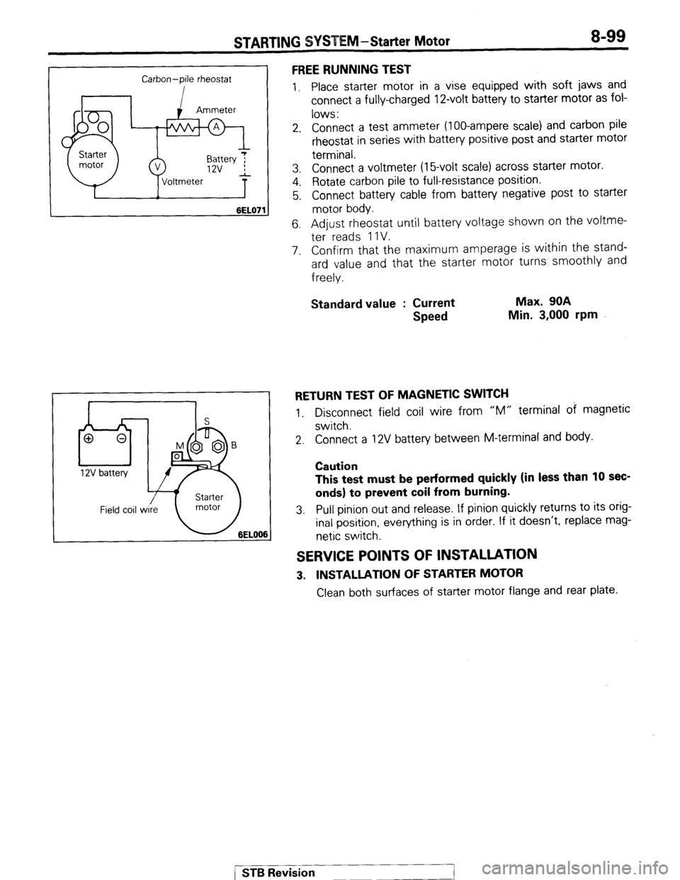
6EL07’ FREE RUNNING TEST
1. Place starter motor in a vise equipped with soft jaws and
connect a fully-charged 12-volt battery to starter motor as fol-
lows :
2. Connect a test ammeter (loo-ampere scale) and carbon pile
rheostat in series with battery positive post and starter motor
terminal.
3. Connect a voltmeter (16volt scale) across starter motor.
4. Rotate carbon pile to full-resistance position.
5. Connect battery cable from battery negative post to starter
motor body.
6. Adjust rheostat until battery voltage shown on the voltme-
ter reads 1 IV.
7. Confirm that the maximum amperage is within the stand-
ard value and that the starter motor turns smoothly and
freely.
Standard value : Current
Speed Max. 90A
Min. 3,000 rpm
RETURN TEST OF MAGNETIC SWITCH
1. Disconnect field coil wire from “M” terminal of magnetic
switch.
2. Connect a 12V battery between M-terminal and body.
Caution
This test must be performed quickly (in less than 10 sec-
onds) to prevent coil from burning.
3. Pull pinion out and release. If pinion quickly returns to its orig-
inal position, everything is in order. If it doesn’t, replace mag-
netic switch.
SERVICE POINTS OF INSTALLATION
3. INSTALLATlON OF STARTER MOTOR
Clean both surfaces of starter motor flange and rear plate.
[ ST6 Revision
1
Page 120 of 284
STARTING SYSTEM -Starter Motor
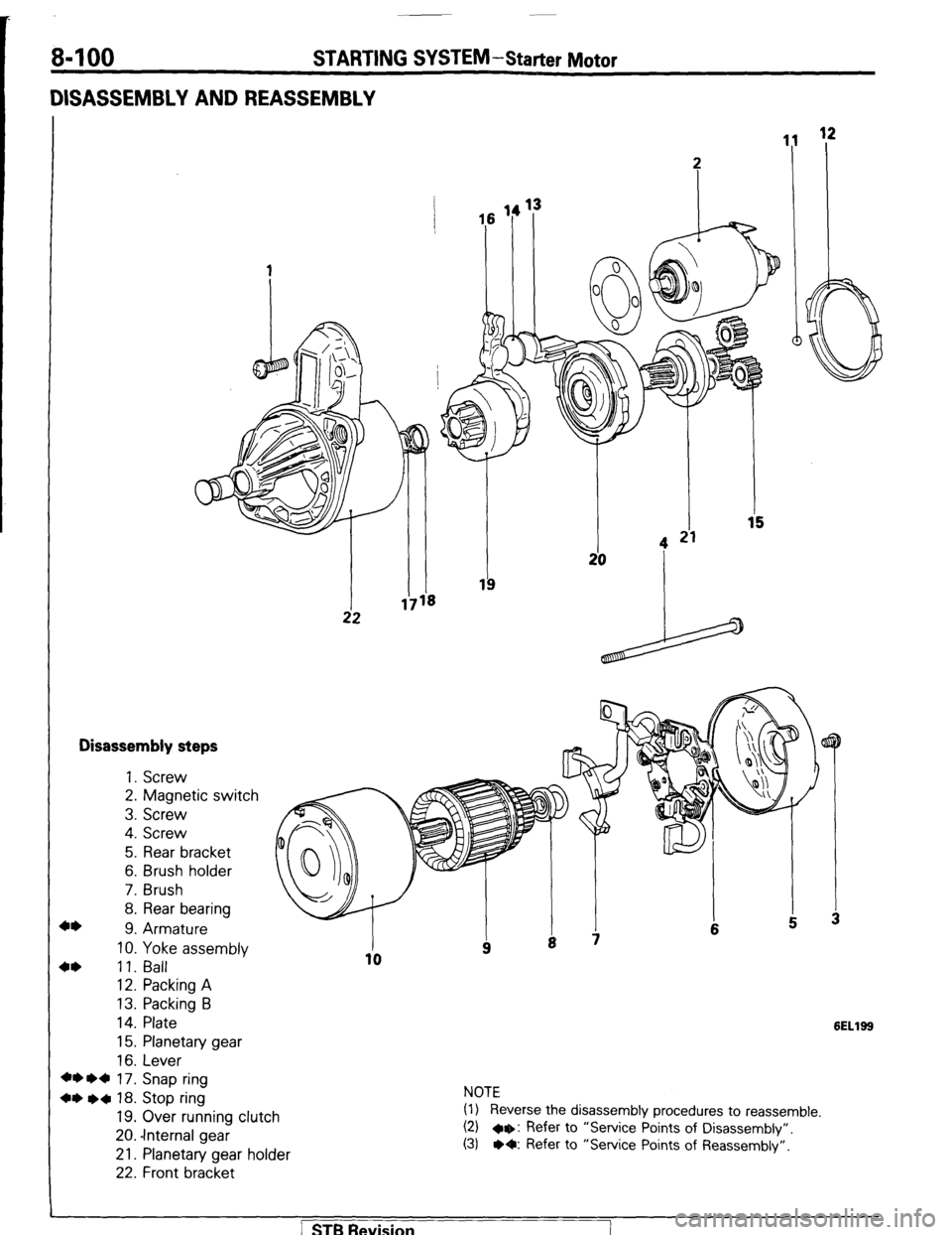
DISASSEMBLY AND REASSEMBLY
Disassembly steps
+* 1. Screw
2. Magnetic switch
3. Screw
4. Screw
5. Rear bracket
6. Brush holder
7. Brush
8. Rear bearing
9. Armature
10. Yoke assembly
4* 11. Ball
12. Packing A
13. Packing B
14. Plate
15. Planetary gear
16. Lever
+* l d 17. Snap ring
+* l a 18. Stop ring
19. Over running clutch
20. -Internal gear
21. Planetary gear holder
22. Front bracket
6ELlSS
NOTE
(1) Reverse the disassembly procedures to reassemble.
(2) a+: Refer to “Service Points of Disassembly”.
(3) l O: Refer to “Service Points of Reassembly”.
] STB Revision