MITSUBISHI MONTERO 1987 1.G Workshop Manual
Manufacturer: MITSUBISHI, Model Year: 1987, Model line: MONTERO, Model: MITSUBISHI MONTERO 1987 1.GPages: 284, PDF Size: 14.74 MB
Page 141 of 284
IGNITION SYSTEM-Distributor 8-121
Distributor
w 6EL093
/” A
I -1-- Socket
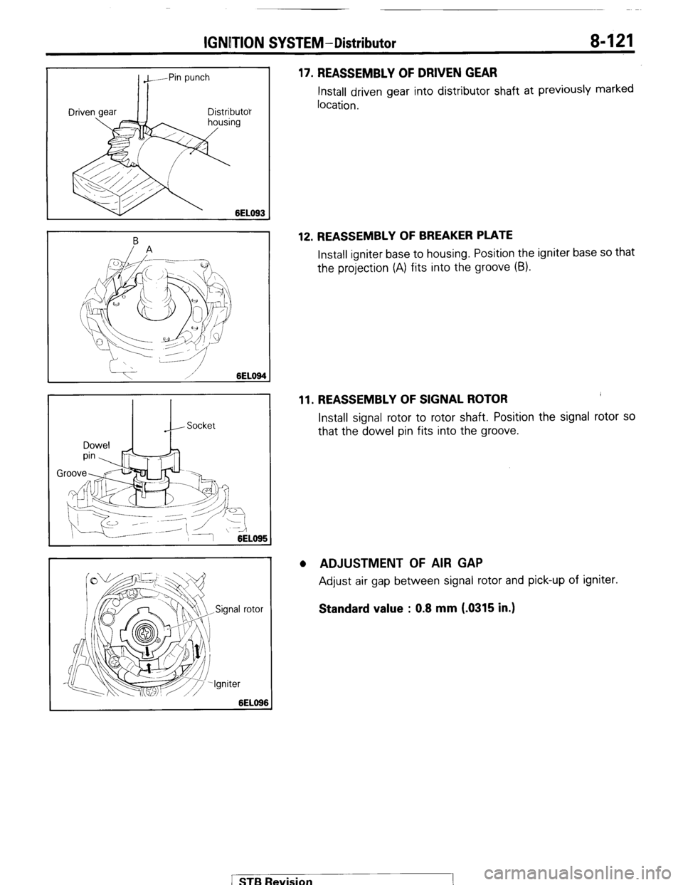
17. REASSEMBLY OF DRIVEN GEAR Install
driven gear into distributor shaft at previously marked
location.
12. REASSEMBLY OF BREAKER PLATE Install igniter base to housing. Position the igniter base so that
the projection (A) fits into the groove (9).
11. REASSEMBLY OF SIGNAL ROTOR Install signal rotor to rotor shaft. Position the signal rotor so
that the dowel pin fits into the groove.
. ADJUSTMENT OF AIR GAP Adjust air gap between signal rotor and pick-up of igniter.
Standard value : 0.8 mm (.0315 in.)
1 STB Revision
Page 142 of 284
8-122 IGNITION SYSTEM - Ugnition Switch
IGNITION SWITCH
REMOVAL AND INSTALLATION
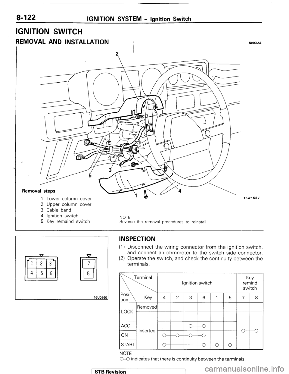
Removal steps
1. Lower column cover
2. Upper column cover
3. Cable band
4. Ignition switch
5. Key remaind switch NOTE Reverse the removal procedures to reinstall
NOEGLAE
16W1557
16UO36C
!I
INSPECTION (1) Disconnect the wiring connector
from the ignition switch,
and connect an ohmmeter to the
switch side connector. (2) Operate the switch, and check the continuity between the
terminals.
START / Ignition switch
NOTE
O-C indicates that there is continuity between the terminals. 1 STB Revision -7
Page 143 of 284
METERS AND GAUGES-Specifications
METERS AND GAUGES
8-123
SPECIFICATIONS
GENERAL SPECIFICATIONS
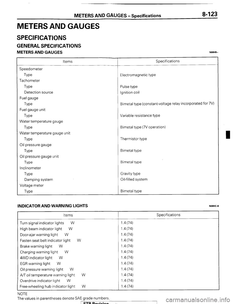
METERS AND GAUGES NOEHB-
Items
Speedometer
Type
Tachometer
Type
Detection source
Fuel gauge
Type
Fuel gauge unit
Type
Water temperature gauge
Type
Water temperature gauge unit
Type
Oil pressure gauge
Type
Oil pressure gauge unit
Type
Inclinometer
Type
Damping system
Voltage meter
Type Specifications
Electromagnetic type
Pulse type
Ignition coil
Bimetal type (constant-voltage relay incorporated for 7V)
Variable resistance type
Bimetal type (7V operation)
Thermistor type
Bimetal type
Bimetal type
Gravity type
Oil-filled system
Bimetal type
INDICATOR AND WARNING LIGHTS
NOEHC-B
Items Specifications
Turn signal indicator lights
W 1.4 (74)
High beam indicator light W 1.4 (74)
Door-ajar warning light W 1.4 (74)
Fasten seat belt indicator light W 1.4 (74)
Brake warning light W 1.4 (74)
Charging warning light W 1.4 (74)
4WD indicator light W 1.4 (74)
EGR warning light W 1.4 (74)
Oil pressure warning light W 1.4 (74)
A/T oil temperature warning light
W 1.4 (74)
Overdrive indicator light
W 1.4 (74)
Free-wheeling hub indicator light W 1.4 (74)
NOTE
The values in parentheses denote SAE grade numbers.
1 STB Revision ”
Page 144 of 284
8-124
BUZZER METERS AND
GAUGES - Specifications
Items
Range of voltage used V
While buzzing (Terminal voltage at 13 V)
Sound pressure dB
Fundamental frequency Hz IO-16
53-7
goo* 150 Specifications
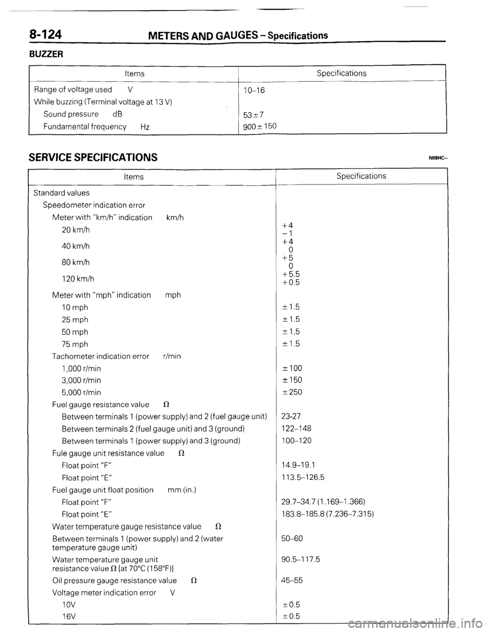
SERVICE SPECIFICATIONS
Items Specifications
Standard values
Speedometer indication error
Meter with “km/h” indication km/h
20 km/h f4
-1
40 km/h +4
0
80 km/h +5
0
120 km/h +5.5
+0.5
Meter with “mph” indication
mph
10 mph +- 1.5
25 mph + 1.5
50 mph +I.5
75 mph k 1.5
Tachometer indication error r/min
1,000 r/min *IO0
3,000 r/min +150
5,000 r/min f 250
Fuel gauge resistance value R
Between terminals 1 (power supply) and 2 (fuel gauge unit) 23-27
Between terminals 2 (fuel gauge unit) and 3 (ground) 122-l 48
Between terminals 1 (power supply) and 3 (ground) 100-l 20
Fule gauge unit resistance value R
Float point “F” 14.9-19.1
Float point “E” 113.5-l 26.5
Fuel gauge unit float position mm (in.)
Float point “F” 29.7-34.7 (1.169-l .366)
Float point “E” 183.8-185.8(7.236-7.315)
Water temperature gauge resistance value R
Between terminals 1 (power supply) and 2 (water 50-60
temperature gauge unit)
Water temperature gauge unit 90.5-I 17.5
resistance value R [at 70°C (158”F)l
Oil pressure gauge resistance value 1R 45-55
Voltage meter indication error V
IOV to.5
16V k 0.5
( ST6 Revision
-7
Page 145 of 284
METERS AND GAUGES-Specifications /Troubleshooting 8425
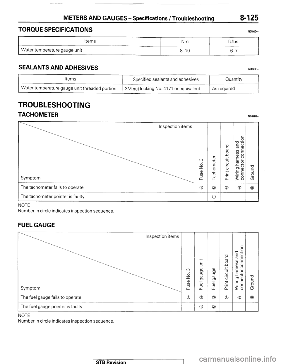
TORQUE SPECIFICATIONS
Items Nm ft.lbs.
Water temperature gauge unit 8-10 6-7
SEALANTS AND ADHESIVES
Items
Water temperature gauge unit threaded portion Specified sealants and adhesives
3M nut locking No. 4171 or equivalent Quantity
As required
TROUBLESHOOTING
TACHOMETER NOBHH-
Inspection items
Symptom
The tachometer fails to operate
I The tachometer pointer is faulty
NOTE
Number in circle indicates inspection sequence.
FUEL GAUGE
Inspection items
Symptom
The fuel gauge fails to operate
The fuel gauge pointer is faulty
NOTE
Number in circle indicates inspection sequence.
1 STB Revision
Page 146 of 284
8-126 METERS AND GAUGES -Troubleshooting
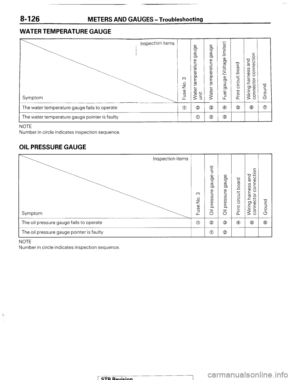
WATER TEMPERATURE GAUGE
Symptom
The water temperature gauge fails to operate
-0
c
2
(5
a 0 0
0 a
I The water temperature gauge pointer is faulty a NOTE
Number in circle indicates inspection sequence.
OIL PRESSURE GAUGE jnspection items
Symptom
0
0
a The oil pressure gauge fails to operate
The oil pressure gauge pointer is faulty
NOTE
Number in circle indicates inspection sequence
( STB Revision
-IIII
Page 147 of 284
METERS AND GAUGES -Troubleshooting 8-127
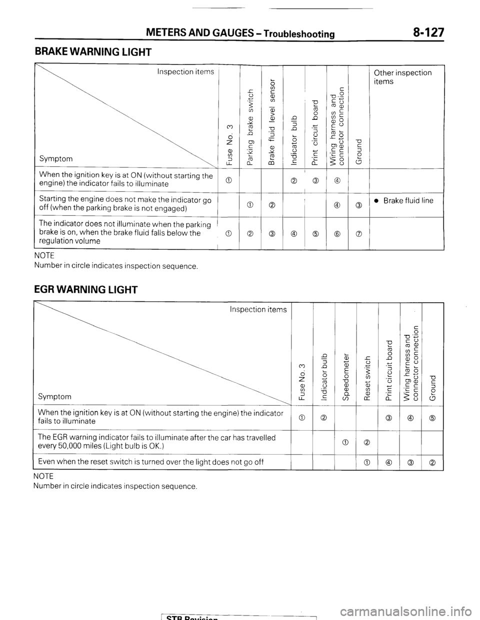
BRAKE WARNING LIGHT
Inspection items
Other inspection
items
Symptom
When the ignition key is at ON (without starting the
engine) the indicator fails to illuminate
Starting the engine does not make the indicator go
off (when the parking brake is not engaged) t 0 0
c
The indicator does not illuminate when the parking
brake is on, when the brake fluid falls below the
regulation volume
a a Co
NOTE
Number in circle indicates inspection sequence.
EGR WARNING LIGHT
U
5
P
W
0
Co When the ignition key is at ON (without starting the engine) the indicator
fails to illuminate
0 The EGR warning indicator fails to illuminate after the car has travelled
every 50,000 miles (Light bulb is OK.)
Even when the reset switch is turned over the light does not go off 0 0
0
I
NOTE
Number in circle indicates inspection sequence.
[ STB Revision
Page 148 of 284
8-128 METERS AND GAUGES - Circuit Diagram
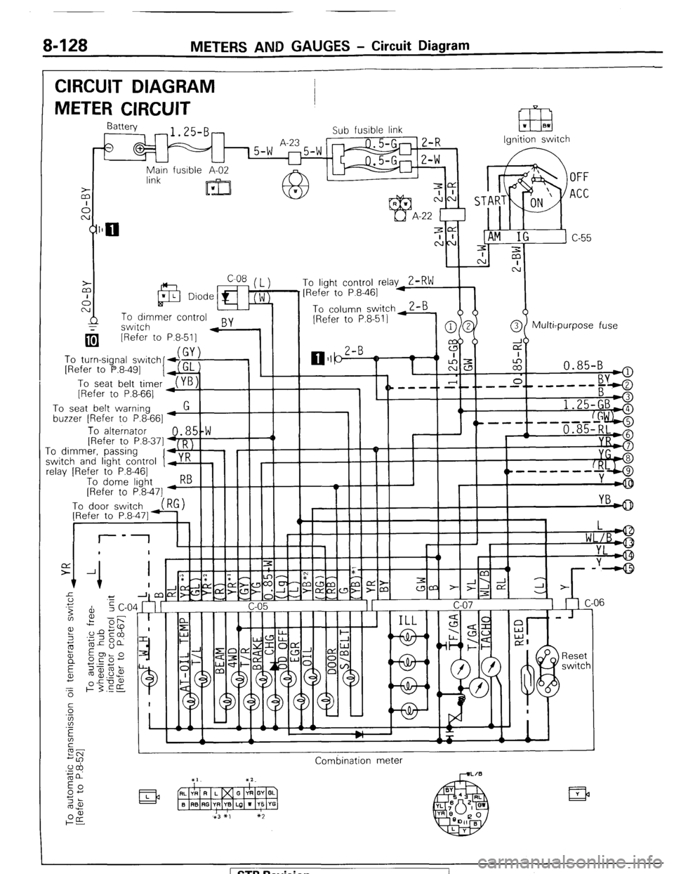
CIRCUIT DIAGRAM
METER CIRCUIT
Ignition switch
q [Refer to
To turn-signal switch
[Refer to P.8-491
I
To seat belt timer
[Refer to P.8-661 P.8-511 -
To seat belt warning
buzzer [Refer to P.8-661
1.25-GBA
, ^.
To alternator 48,5!W III -1 / 1 , 1 '----f--d+ii$$j IRefer to P.8.371 D I
.I_ -0 dimmkr, passinq
‘I+,:’ ! I I I II -I
I r I I I II YI
;witch and light control y K
clay [Refer to P.8-461
To dome liaht 5--hIIII I
----m-w-
[Refer to P&47] -w
Combination meter
( STB Revision
Page 149 of 284
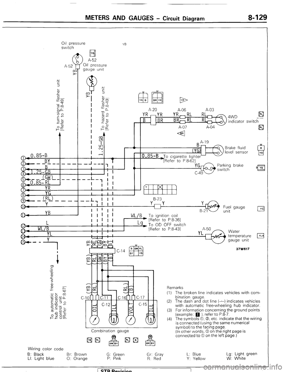
METERS AND GAUGES - Circuit Diagram 8-129
011 pressure
switch YB
H I
>
A-52
Oil pressure
gauge unit
(
A-52
UY
>
-0.85-B
r.., !
YB
A-20 A-06 A-03
YR mYR YR,RL RL 4WD El B indicator switch
-- L7 I I 1 8-23
I I I I I
I 1 !
Fuel 1 1 gauge
unit
L
WL/B
YL
g-- y
1
I
I I I I I I LY)T~ OD OFF switch
1 1 I
I ' ; [Refer to P.8-431 I I
I . . I
'4 8.
Combination gauge
Wiring color code
6: Black Br: Brown G: Green Gr: Gray
LI: Light blue 0: Orange P: Pink
R: Red
Y Water
temperature
gauge unit
Remarks
(I) The broken line indicates vehicles with com-
bination gauge.
(2) The dash and dot line (-.-) indicates vehicles
with automatic free-wheeling hub indicator.
(3) For information concerning the ground points
(example: 0 ). refer to P.8-7.
(4) The symbols @I,@, etc. indicate that the wiring
is connected (using the same numerical
symbol) to the facing page.
(In other words, 0 on the right page is
connected to 0 on the left page.)
L: Blue
Y: Yellow Lg: Light green
W: White
/ STB Revision
Page 150 of 284
8430 METERS AND GAUGES - Service Adjustment Procedures.
SERVICE BJUSTMENT. PROCEDURES
SPEEDOMETER INSPECTION NOSHIAA
I. Adjust tire inflation pressure to the standard value. (Refer
to’GROUP 22 WHEELS AND TIRES-General Specifications)
2. Use speedometer tester to make sure that the speedome-
ter indication error is within the standard value.
Standard value :
Meter with “km/h” indication km/h
20 km/h +4
-1
40 km/h +4
0
80 km/h +5
0
120 km/h + 5.5
+0.5
Meter with “mph” indication
mph
10 mph
25 mph
50 mph
75 mph +I.5
21.5
+I.5
&I.5
Caution
1 When using a speedometer tester to inspect the
speedometer, be sure to chock the non-drive wheels
to prevent the vehicle from moving. Also be sure to
set the transfer shift lever to “2H”.
2 If there is a special regulation for speedometer
indication error in the area where the ‘vehicle is
operated, be sure to meet the requirement of the
regulation.
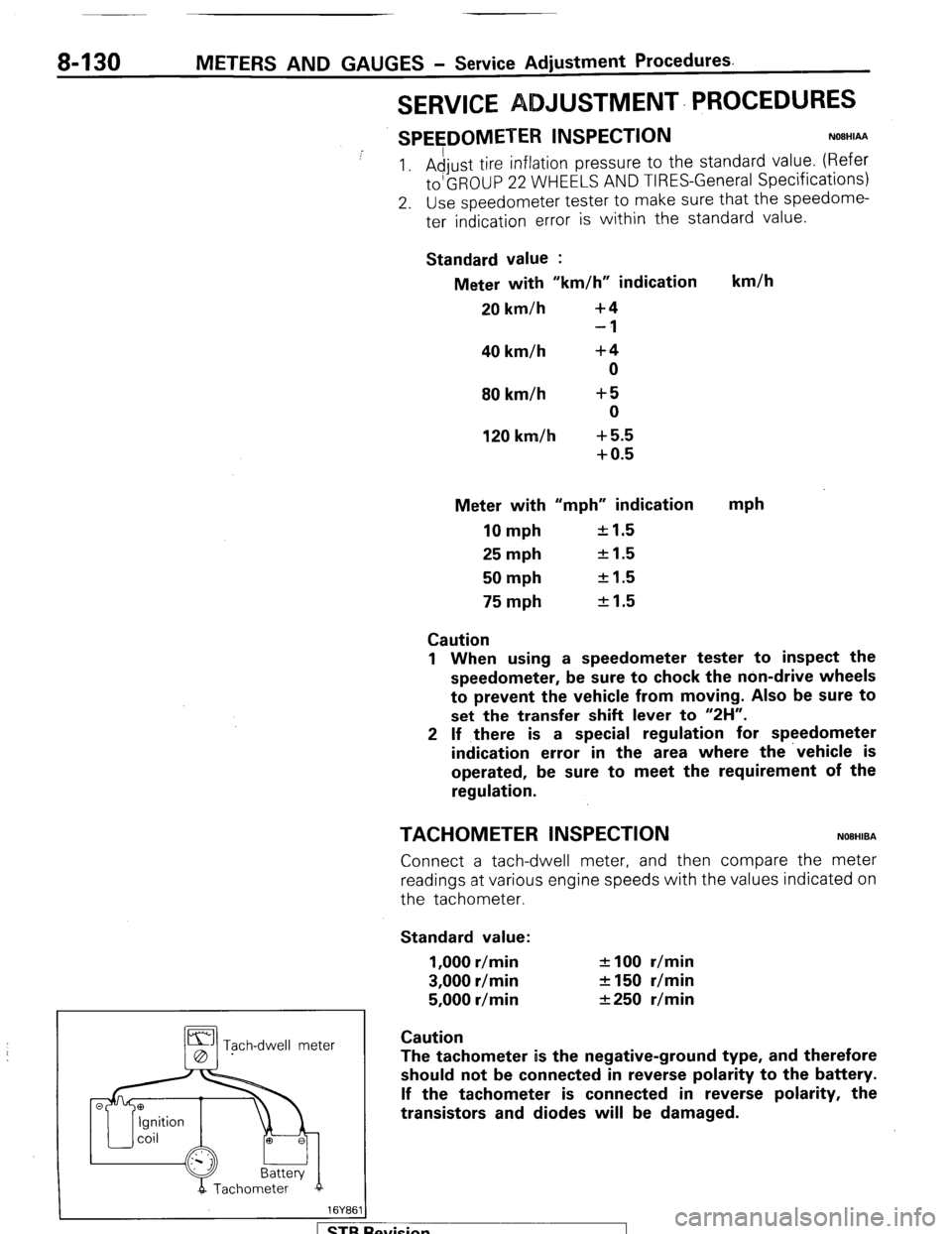
TACHOMETER INSPECTION NOBHIBA
Connect a tach-dwell meter, and then compare the meter
readings at various engine speeds with the values indicated on
the tachometer.
Standard value:
1,000 r/min
3,000 r/min
5,000 r/min f 100 r/min
2150 r/min
&250 r/min
Tgch-dwell meter Caution
The tachometer is the negative-ground type, and therefore
should not be connected in reverse polarity to the battery.
If the tachometer is connected in reverse polarity, the
transistors and diodes will be damaged.
evision