MITSUBISHI MONTERO 1987 1.G Workshop Manual
Manufacturer: MITSUBISHI, Model Year: 1987, Model line: MONTERO, Model: MITSUBISHI MONTERO 1987 1.GPages: 284, PDF Size: 14.74 MB
Page 151 of 284
METERS AND GAUGES - Service Adiustment Procedures 8-131
r
(harness side) 16W834
Stopper (upper)
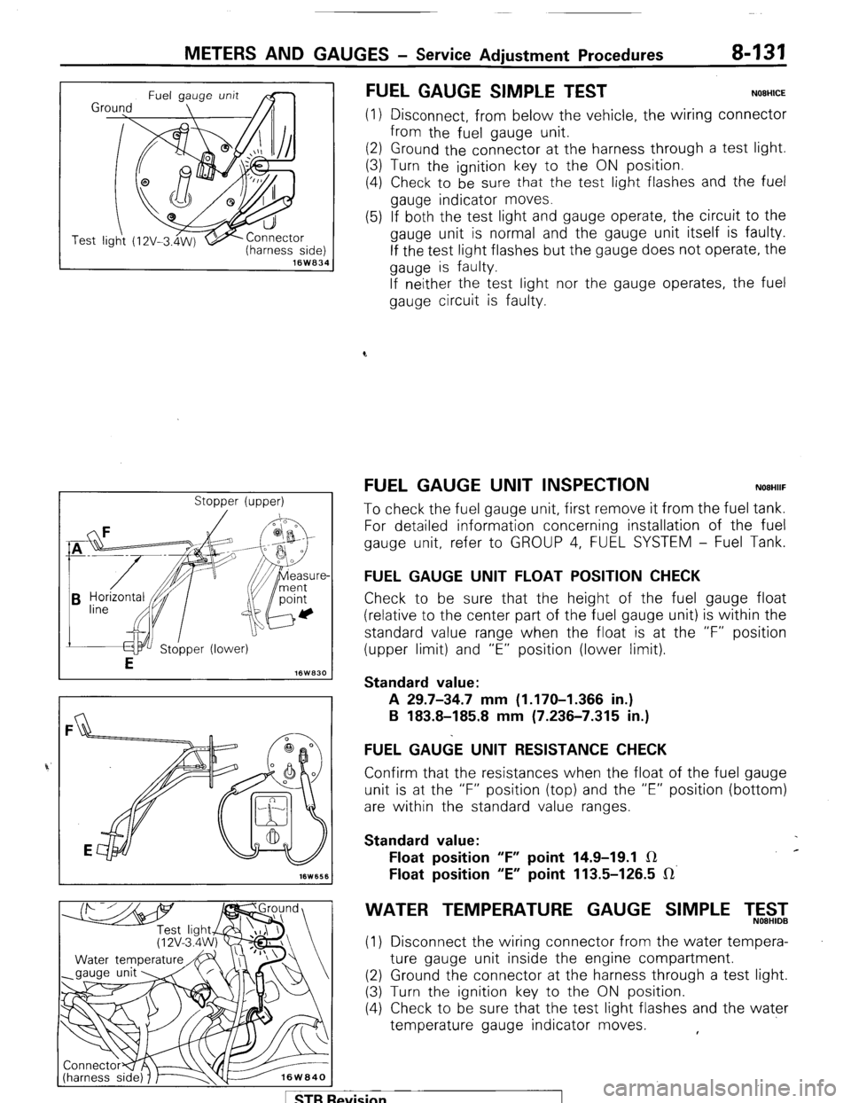
FUEL GAUGE SIMPLE TEST NOEHICE
(1) Disconnect, from below the vehicle, the wiring connector
from the fuel gauge unit.
(2) Ground the connector at the harness through a test light.
(3) Turn the ignition key to the ON position.
(4) Check to be
sure that the test light flashes and the fuel
gauge indicator moves.
(5) If both the test light and gauge operate, the circuit to the
gauge unit is normal and the gauge unit itself is faulty.
If the test light flashes but the gauge does not operate, the
gauge is faulty.
If neither the test light nor the gauge operates, the fuel
gauge circuit is faulty.
FUEL GAUGE UNIT INSPECTION NOEHIIF
To check the fuel gauge unit, first remove it from the fuel tank.
For detailed information concerning installation of the fuel
gauge unit, refer to GROUP 4, FUEL SYSTEM - Fuel Tank.
FUEL GAUGE UNIT FLOAT POSITION CHECK
Check to be sure that the height of the fuel gauge float
(relative to the center part of the fuel gauge unit) is within the
standard value range when the float is at the “F” position
(upper limit) and “E” position (lower limit).
Standard value:
A 29.7-34.7 mm (1.170-I .366 in.)
B 183.8-185.8 mm (7.236-7.315 in.)
FUEL GA&E UNIT RESISTANCE CHECK
Confirm that the resistances when the float of the fuel gauge
unit is at the “F” position (top) and the “E” position (bottom)
are within the standard value ranges.
Standard value:
Float position “F” point 14.9-19.1 IR c
Float position “E” point 113.5-126.5 IR’
WATER TEMPERATURE GAUGE SIMPLE T,5$2
(1) Disconnect the wiring connector from the water tempera-
ture gauge unit inside the engine compartment.
(2) Ground the connector at the harness through a test light.
(3) Turn the ignition key to the ON position.
(4) Check to be sure that the test light flashes and the water
temperature gauge indicator moves. ,
1 STB Revision
Page 152 of 284
8-132 METERS AND GAUGES - Service Adjustment Procedures
(5) If both the test light and gauge operate, the circuit to the
gauge unit is normal and the gauge unit itself is faulty.
If the test light flashes but the gauge does not operate, the
gauge is faulty.
If 1 neither the test light nor the gauge operates, the water
temperature gauge circuit is faulty.
Se
VVATER TEMPERATURE GAUGE UNIT ONSPEC-
TION
NOBHIKD
To check the water temperature gauge unit, first remove it
from the intake manifold.
For detailed information concerning installation of the water
temperature gauge unit, refer to GROUP 11, INTAKE AND
EXHAUST SYSTEM - Intake Manifold.
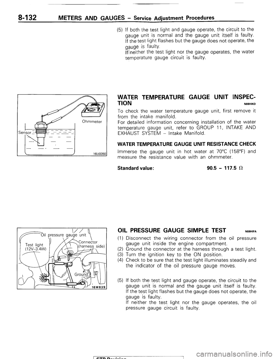
WATER TEMPERATURE GAUGE UNIT RESISTANCE CHECK
Immerse the gauge unit in hot water at 70°C (158°F) and
measure the resistance value with an ohmmeter.
Standard value: 90.5 - 117.5 LR
OIL PRESSURE GAUGE SIMPLE TEST NOEHIFA
(1) Disconnect the wiring connector from the oil pressure
gauge unit inside the engine compartment.
(2) Ground the connector at the harness through a test light.
(3) Turn the ignition key to the ON position.
(4) Check to be sure that the test light illuminates steadily and
the indicator of the oil pressure gauge moves.
(5) If both the test light and gauge operate, the circuit to the
gauge unit is normal and the gauge unit itself is faulty.
If the test light flashes but the gauge does not operate, the
gauge is faulty.
If neither the test light nor the gauge operates, the oil
pressure gauge circuit is faulty.
1 STB Revision
-7
Page 153 of 284
METERS AND GAUGES - Service Adjustment Procedures 8-133
IOil p Oil pressure ressure
gauge unit
1 I Test light
‘@‘(12V - 3.4 I
W)
16W1576
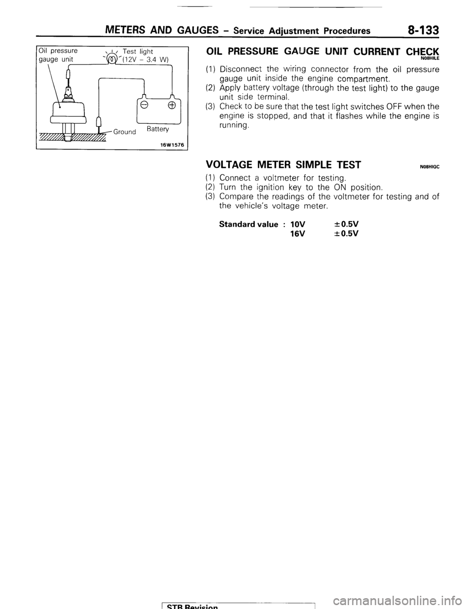
OIL PRESSURE GA GE UNIT CURRENT CHEC,‘l<,
(1) Disconnect the wiring connector from the oil pressure
gauge unit inside the engine compartment.
(2) Apply battery voltage (through the test light) to the gauge
unit side terminal.
(3) Check to be sure that the test light switches OFF when the
engine is stopped, and that it flashes while the engine is
running.
VOLTAGE METER SIMPLE TEST NOEHIGC
(1) Connect a voltmeter for testing.
(2) Turn the ignition key to the ON position.
(3) Compare the readings of the voltmeter for testing and of
the vehicle’s voltage meter. Standard value : 1OV
16V + 0.5v
+ 0.5v
1 STB Revision
Page 154 of 284
8-134 METERS AND GAUGES - Combination Meter
COMBINATION METER
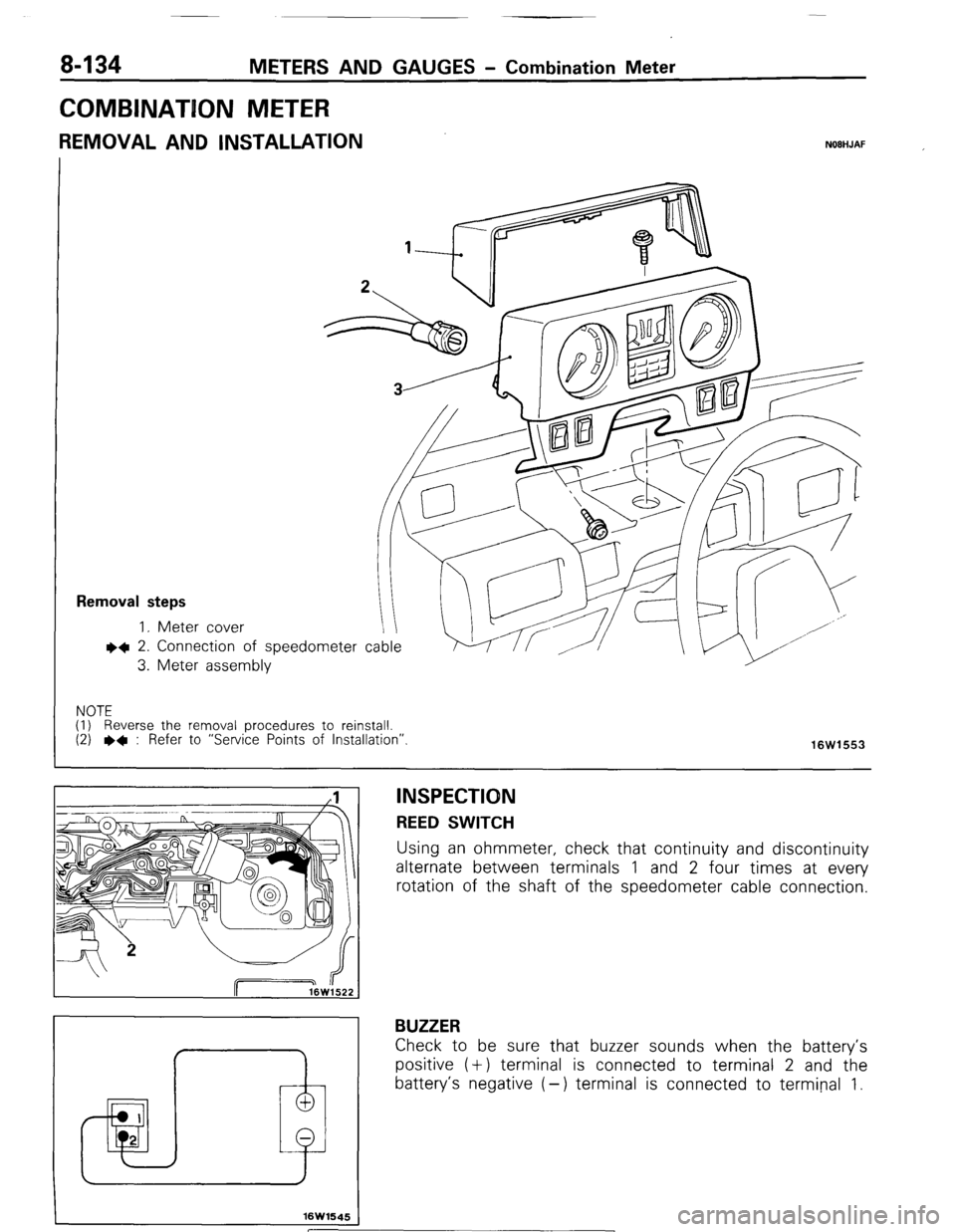
REMOVAL AND INSTALLATION NOBHJAF
Removal steps
1. Meter cover
l 4 2. Connection
3. Meter asset of speedometer cable
nbly
NOTE
(I) Reverse the removal procedures to reinstall.
(2)
l + : Refer to “Service Points of Installation”.
16W1553
I 1 I
I
f
16W1645
INSPECTION REED SWITCH
Using an ohmmeter, check that continuity and discontinuity
alternate between terminals 1 and 2 four times at every
rotation of the shaft of the speedometer cable connection.
BUZZER
Check to be sure that buzzer sounds when the battery’s
positive (+) terminal is connected to terminal 2 and the
battery’s negative (-) terminal is connected to terminal 1.
[ STB Revision
Page 155 of 284
METERS AND GAUGES - Combination Meter 8-135
.3
16WQ25
16W925
10W926
16F554
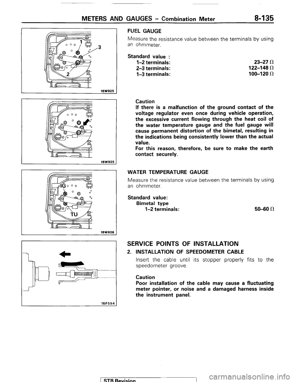
FUEL GAUGE
Measure the resistance value between t.he terminals by using
an ohmmeter.
Standard value :
l-2 terminals:
2-3 terminals:
l-3 terminals: 23-27 R
122-148 Sz
100-120 IR
Caution
If there is a malfunction of the ground contact of the
voltage regulator even once during vehicle operation,
the excessive current flowing through the heat coil of
the water temperature gauge and the fuel gauge will
cause permanent distortion of the bimetal, resulting in
the indications being consistently lower than the actual
value.
For this reason, therefore, be sure to make the earth
contact securely.
WATER TEMPERATURE GAUGE
Measure the resistance value between the terminals by using
an ohmmeter.
Standard value:
Bimetal type
l-2 terminals: 50-80 n
SERVICE POINTS OF INSTALLATION
2. INSTALLATION OF SPEEDOMETER CABLE
Insert the cable until its stopper properly fits to the
speedometer groove.
Caution
Poor installation of the cable may cause a fluctuating
meter pointer, or noise and a damaged harness inside
the instrument panel.
) STB Revision
Page 156 of 284
8-136 METERS AND GAUGES - Combination Meter
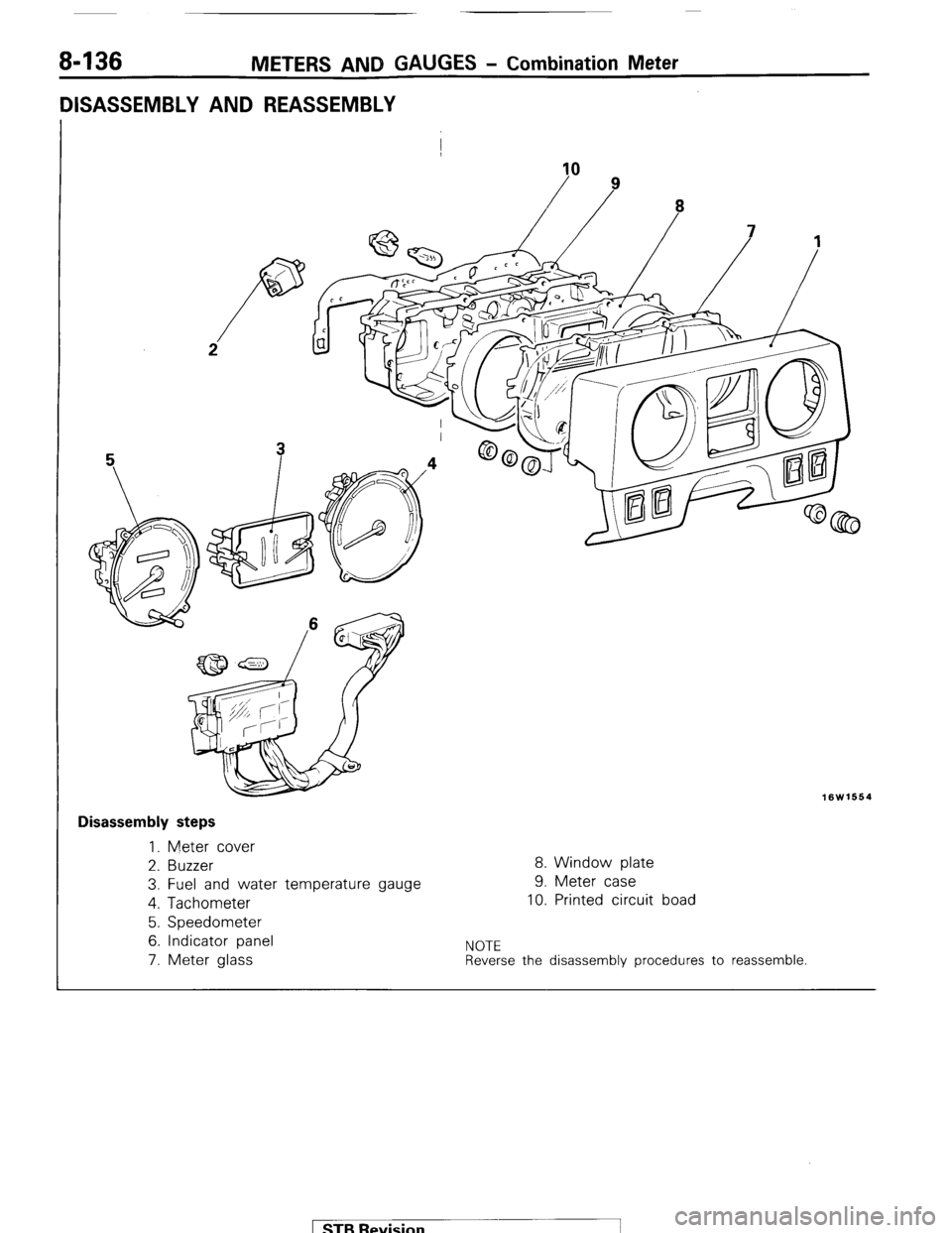
DISASSEMBLY AND REASSEMBLY
I
10
16W1664
I Disassembly steps
1. Meter cover
2. Buzzer
8. Window plate
3. Fuel and water temperature gauge 9. Meter case
4. Tachometer
10. Printed circuit boad
5. Speedometer
6. Indicator panel
NOTE 7. Meter glass Reverse the disassembly procedures to reassemble. 1 STB Revision -1
Page 157 of 284
METERS AND GAUGES - 3-meter Unit
3-METER lJN(IT
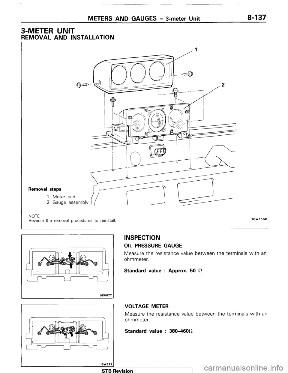
REMOVAL AND INSTALLATION
Removal steps
1. Meter 2.
Gauge
pad
assembly
NOTE
Reverse the removal procedures to reinstall
16W1560
lBW077
INSPECTION OIL
PRESSURE GAUGE
Measure the resistance value between the terminals with an
ohmmeter. Standard value : Approx. 50 CR
VOLTAGE METER
Measure the resistance value between the terminals with an
ohmmeter. Standard value : 380-4601(1
1 STB Revision
Page 158 of 284
8-138 METERS AND GAUGES - s-meter Unit
16W678
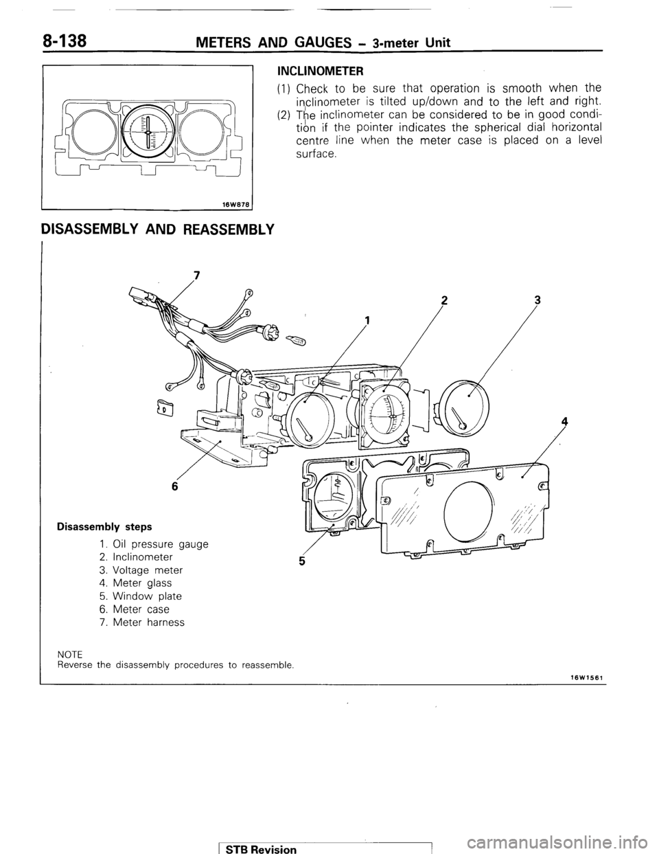
DISASSEMBLY AND REASSEMBLY
INCLINOMETER
(1) Check to be sure that operation is smooth when the
inclinometer is tilted up/down and to the left and right.
(2) The i,nclinometer can be considered to be in good condi-
tion If the pointer indicates the spherical dial horizontal
centre line when the meter case is placed on a level
surface.
6
Disassembly steps
1. Oil pressure gauge
2. Inclinometer
3. Voltage meter
4. Meter glass
5. Window plate
6. Meter case
7. Meter harness
NOTE
Reverse the disassembly procedures to reassemble.
16W1561
1 ST6 Revision
Page 159 of 284
METERS AND GAUGES - s-meter Unit 8-139
Center shaft of
pitching damper plate
Pointer
16W 600
Spherical dial
Spherical
horizontal
16W966
Spherical dial Dial support plate
/ Oil case
Gxizontal centerlinewtationaryframe
Blind plate
16W627
;ide to side inclination Forward or backwarc
Hokizontal line Horizbntal line
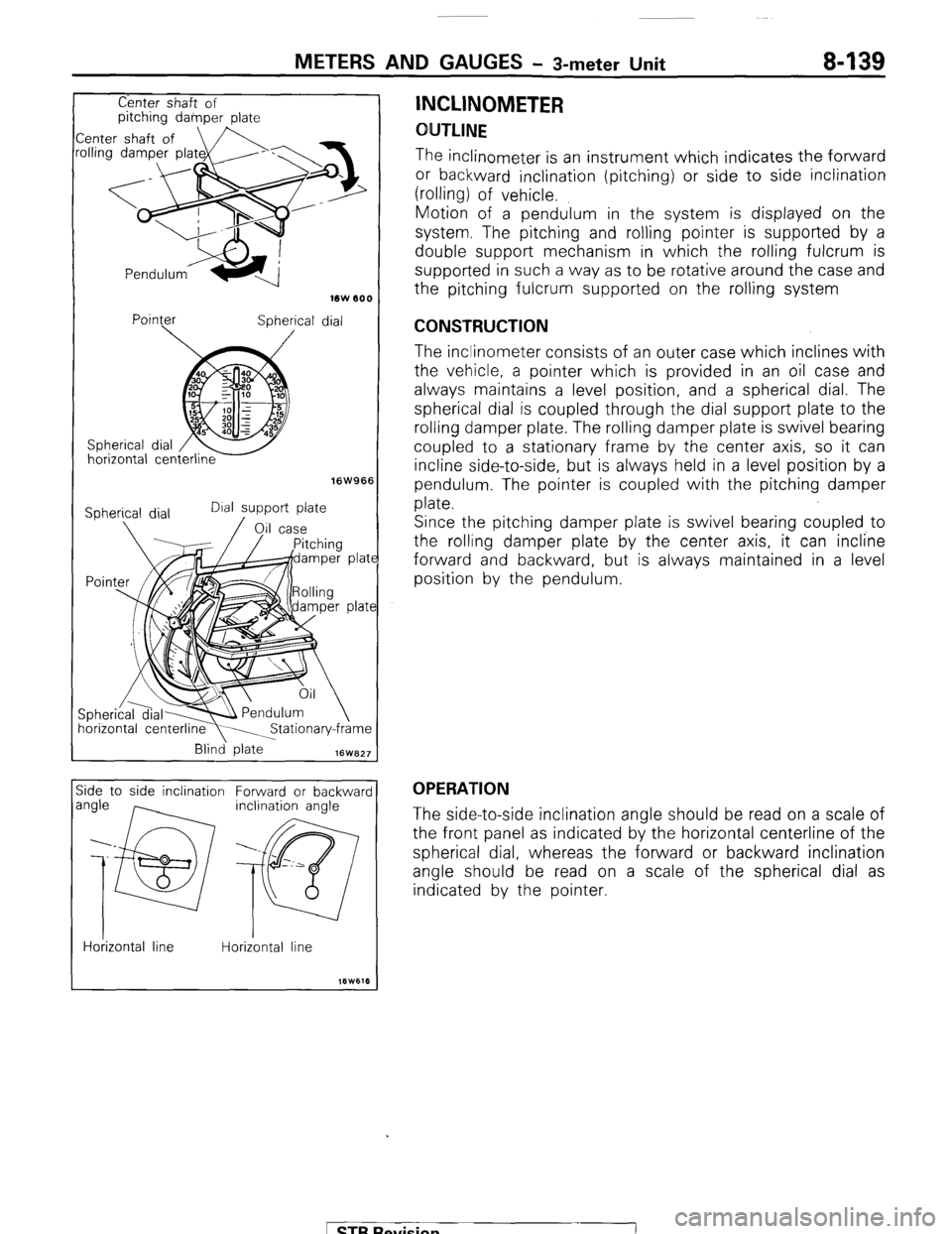
INCLINOMETER
OUTLINE
The inclinometer is an instrument which indicates the forward
or backward inclination (pitching) or side to side inclination
(ding) of vehicle.
Motion of a pendulum in the system is displayed on the
system. The pitching and rolling pointer is supported by a
double support mechanism in which the rolling fulcrum is
supported in such a way as to be rotative around the case and
the pitching fulcrum supported on the rolling system
CONSTRUCTION
The inclinometer consists of an outer case which inclines with
the vehicle, a pointer which is provided in an oil case and
always maintains a level position, and a spherical dial. The
spherical dial is coupled through the dial support plate to the
rolling damper plate. The rolling damper plate is swivel bearing
coupled to a stationary frame by the center axis, so it can
incline side-to-side, but is always held in a level position by a
pendulum. The pointer is coupled with the pitching damper
plate.
Since the pitching damper plate is swivel bearing coupled to
the rolling damper plate by the center axis, it can incline
forward and backward, but is always maintained in a level
position by the pendulum.
OPERATION
The side-to-side inclination angle should be read on a scale of
the front panel as indicated by the horizontal centerline of the
spherical dial, whereas the forward or backward inclination
angle should be read on a scale of the spherical dial as
indicated by the pointer.
[ STB Revision
Page 160 of 284
8-140 METERS AND GAUGES - 3-meter Unit
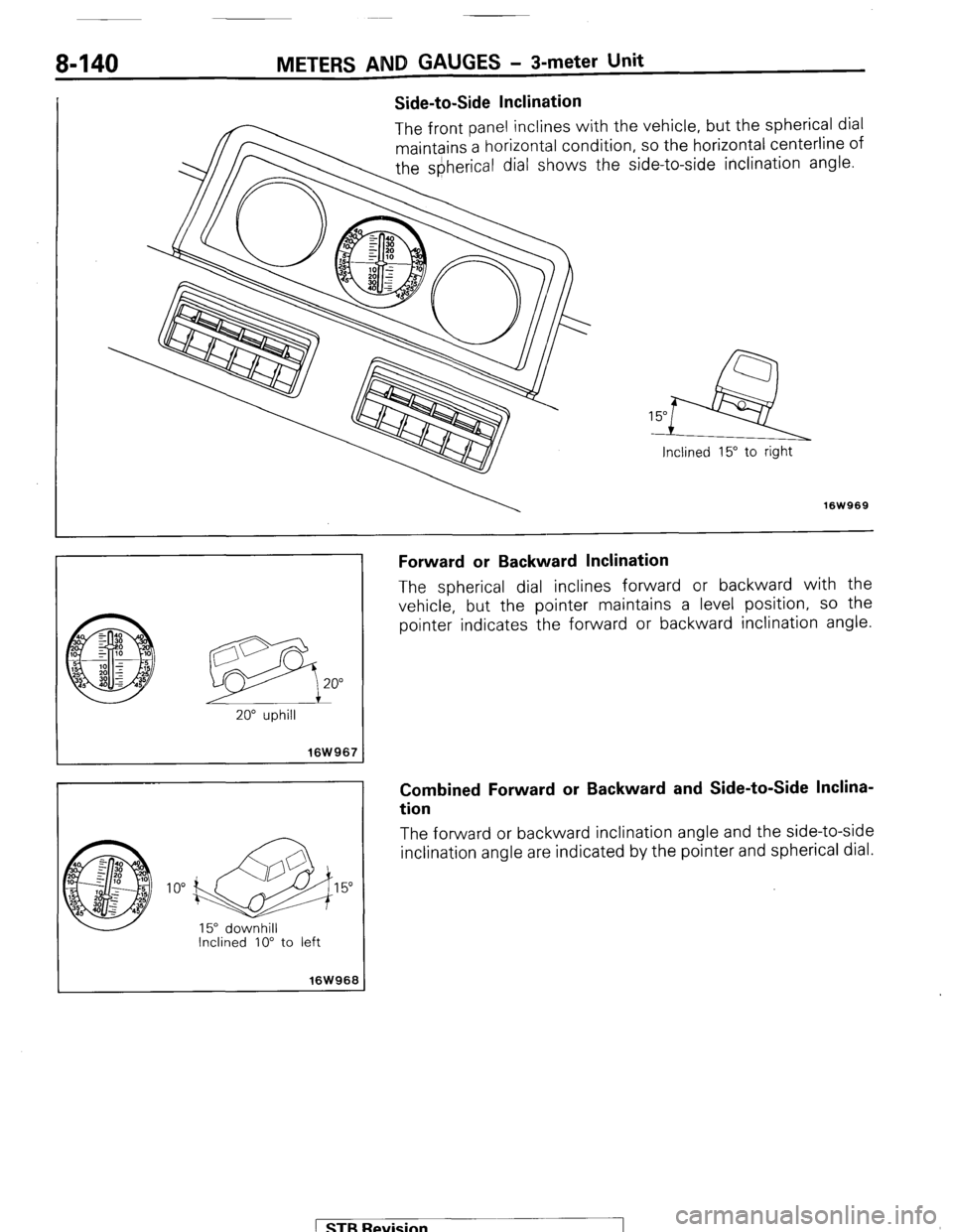
Side-to-Side Inclination
The front panel inclines with the vehicle, but the spherical dial
maintains a horizontal condition, so the horizontal centerline of
the s&lerical dial shows the side-to-side inclination angle.
7
Inclined 15" to right
16W969
@ 10” d15
15” downhill
Inclined IO” to left
I 16W968 I
Forward or Backward Inclination
The spherical dial inclines forward or backward with the
vehicle, but the pointer maintains a level position, so the
pointer indicates the forward or backward inclination angle.
Combined Forward or Backward and Side-to-Side Inclina-
tion
The forward or backward inclination angle and the side-to-side
inclination angle are indicated by the pointer and spherical dial.
1 STB Revision
-7