MITSUBISHI MONTERO 2000 Service Repair Manual
Manufacturer: MITSUBISHI, Model Year: 2000, Model line: MONTERO, Model: MITSUBISHI MONTERO 2000Pages: 1839, PDF Size: 29.19 MB
Page 1681 of 1839
CHASSIS ELECTRICAL -RV Meter54A-20
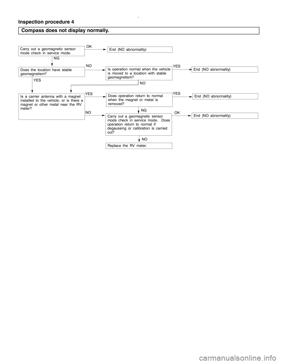
Inspection procedure 4
Compass does not display normally.
NO
NO
NG
Replace the RV meter.
Is a carrier antenna with a magnet
installed to the vehicle, or is there a
magnet or other metal near the RV
meter?YES
YES
YESEnd (NO abnormality)
NO
YESEnd (NO abnormality)Does operation return to normal
when the magnet or metal is
removed?
NO
Carry out a geomagnetic sensor
mode check in service mode. Does
operation return to normal if
degaussing or calibration is carried
out?OKEnd (NO abnormality)
Does the location have stable
geomagnetism?Is operation normal when the vehicle
is moved to a location with stable
geomagnetism?
OKEnd (NO abnormality)Carry out a geomagnetic sensor
mode check in service mode.
NG
www.WorkshopManuals.co.uk
Purchased from www.WorkshopManuals.co.uk
Page 1682 of 1839
CHASSIS ELECTRICAL -RV Meter54A-21
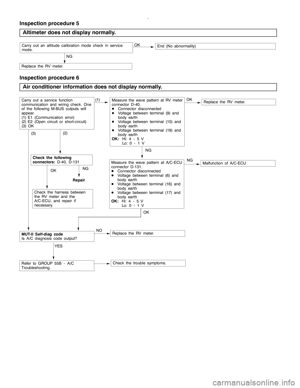
Inspection procedure 5
Altimeter does not display normally.
NG
Replace the RV meter.
OKEnd (No abnormality)Carry out an altitude calibration mode check in service
mode.
Inspection procedure 6
Air conditioner information does not display normally.
NG
Replace the RV meter.
NG
Replace the RV meter.
(1)
Check the trouble symptoms. NO
MUT-II Self-diag code
Is A/C diagnosis code output?
Carry out a service function
communication and wiring check. One
of the following M-BUS outputs will
appear.
(1) E1 (Communication error)
(2) E2 (Open circuit or short-circuit)
(3) OKMeasure the wave pattern at RV meter
connector D-40.
DConnector disconnected
DVoltage between terminal (9) and
body earth
DVoltage between terminal (10) and
body earth
DVoltage between terminal (19) and
body earth
OK:Hi: 4 - 5 V
Lo: 0 - 1 V
Malfunction of A/C-ECU OKMeasure the wave pattern at A/C-ECU
connector D-131.
DConnector disconnected
DVoltage between terminal (6) and
body earth
DVoltage between terminal (16) and
body earth
DVoltage between terminal (17) and
body earth
OK:Hi: 4 - 5 V
Lo: 0 - 1 V (2)Check the following
connectors:D-40, D-131
NG
OK
Check the harness between
the RV meter and the
A/C-ECU, and repair if
necessary. (3)
Refer to GROUP 55B - A/C
Troubleshooting.YES
OK
Repair
www.WorkshopManuals.co.uk
Purchased from www.WorkshopManuals.co.uk
Page 1683 of 1839
CHASSIS ELECTRICAL -RV Meter54A-22
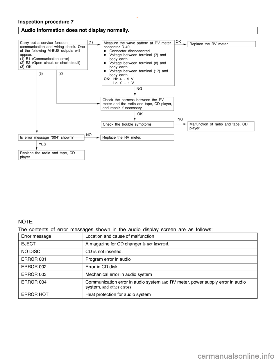
Inspection procedure 7
Audio information does not display normally.
Replace the RV meter.
NG
Replace the radio and tape, CD
player
(1)
Check the trouble symptoms.
Carry out a service function
communication and wiring check. One
of the following M-BUS outputs will
appear.
(1) E1 (Communication error)
(2) E2 (Open circuit or short-circuit)
(3) OKMeasure the wave pattern at RV meter
connector D-40.
DConnector disconnected
DVoltage between terminal (7) and
body earth
DVoltage between terminal (8) and
body earth
DVoltage between terminal (17) and
body earth
OK:Hi: 4 - 5 V
Lo: 0 - 1 V
Malfunction of radio and tape, CD
player OK
(2)
Check the harness between the RV
meter and the radio and tape, CD player,
and repair if necessary. (3)
YESOK
NG
Is error message “004” shown?NOReplace the RV meter.
NOTE:
The contents of error messages shown in the audio display screen are as follows:
Error messageLocation and cause of malfunction
EJECTA magazine for CD changeris not inserted.
NO DISCCD is not inserted.
ERROR 001Program error in audio
ERROR 002Error in CD disk
ERROR 003Mechanical error in audio system
ERROR 004Communication error in audio systemand RV meter,power supply error in audio
system, and other errors
ERROR HOTHeat protection for audio system
www.WorkshopManuals.co.uk
Purchased from www.WorkshopManuals.co.uk
Page 1684 of 1839
R
V METE R
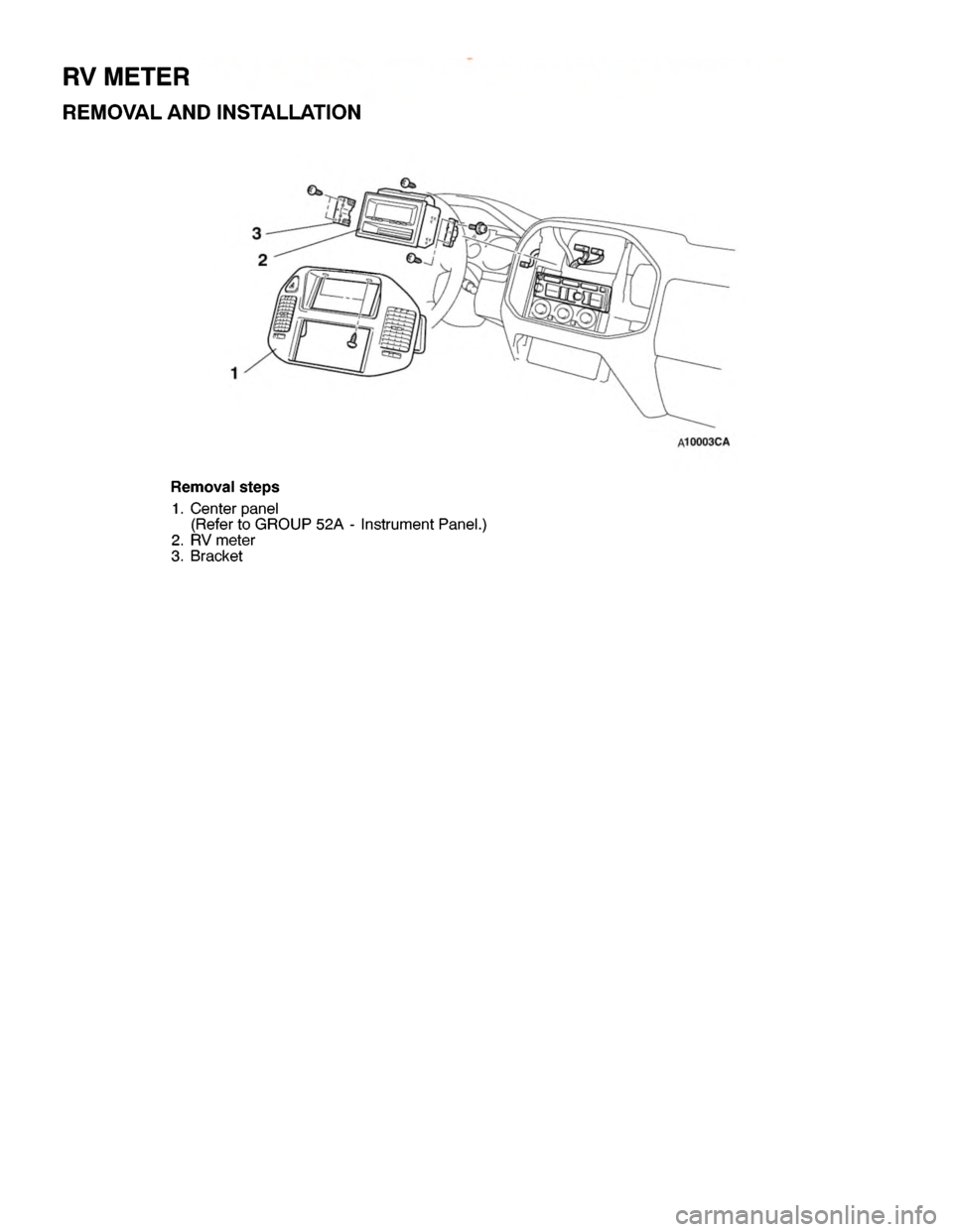
R EM OVA L AND IN STA LLA TIO N
2
1 3
R em ovals te p s
1 . C ente r panel
( R efe r to GRO UP 52A -In str u m entP anel. )
2 . R V mete r
3 . B ra cke t
w
ww.W ork sh opM an uals .c o .u k
P urc h ased f r o m w ww.W ork sh opM an uals .c o .u k
Page 1685 of 1839
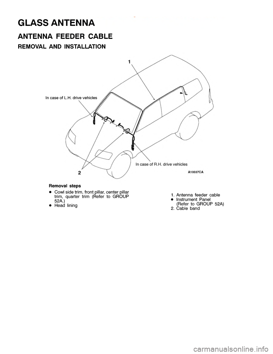
I
n ca se ofR .H .d riv e ve hic le s
R em oval ste p s
D Cow ls id e tr im ,fr o ntp illa r, ce nte r pilla r
t r im ,quarte r tr im (R efe r to GRO UP
5 2A .)
D Head lin in g 1
. A nte nna fe eder ca ble
D In str u m ent Panel
( R efe r to GRO UP 52A )
2 . C able band
w
ww.W ork sh opM an uals .c o .u k
P urc h ased f r o m w ww.W ork sh opM an uals .c o .u k
Page 1686 of 1839

SMART WIRING
SYSTEM (SWS)
Click on the applicable bookmark to selected the required model year.
www.WorkshopManuals.co.uk
Purchased from www.WorkshopManuals.co.uk
Page 1687 of 1839

54B-1
SMART WIRING
SYSTEM (SWS)
CONTENTS
GENERAL INFORMATION 2................
SPECIAL TOOLS 7........................
TROUBLESHOOTING 8....................
Standard Flow of Diagnostic
Troubleshooting 8...........................
Diagnostic Function 8........................
Diagnosis Code Chart 9.....................Diagnosis Code Inspection Procedures 10.....
Trouble Symptom Chart 13...................
Inspection Procedure for Trouble
Symptoms 17...............................
Check at ECU Terminals 54..................
ON-VEHICLE SERVICE 60.................
Adjustment Procedures for SWS Function 60..
www.WorkshopManuals.co.uk
Purchased from www.WorkshopManuals.co.uk
Page 1688 of 1839
SWS -General InformationSWS -General Information54B-2
GENERAL INFORMATION
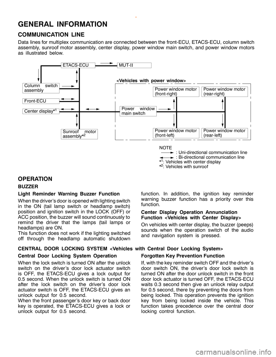
COMMUNICATION LINE
Data lines for multiplex communication are connected between the front-ECU, ETACS-ECU, column switch
assembly, sunroof motor assembly, center display, power window main switch, and power window motors
as illustrated below.
ETACS-ECUMUT-II
Column switch
assembly
Front-ECU
Power window
main switch
Power window motor
(front-right)
Center display*1
Sunroof motor
assembly*2Power window motor
(front-left)
Power window motor
(rear-right)
Power window motor
(rear-left)
NOTE
: Uni-directional communication line
: Bi-directional communication line
*
1: Vehicles with center display
*2: Vehicles with sunroof
OPERATION
BUZZER
Light Reminder Warning Buzzer Function
When the driver’s door is opened with lighting switch
in the ON (tail lamp switch or headlamp switch)
position and ignition switch in the LOCK (OFF) or
ACC position, the buzzer will sound continuously to
remind the driver that the lamps (tail lamps or
headlamps) are ON.
This function does not work if the lighting switched
off through the headlamp automatic shutdownfunction. In addition, the ignition key reminder
warning buzzer function has a priority over this
function.
Center Display Operation Annunciation
Function
On vehicles with center display, the buzzer (peeps)
sounds when the operation switch of the audio
and navigation system is pressed.
CENTRAL DOOR LOCKING SYSTEM
Central Door Locking System Operation
When the lock switch is turned ON after the unlock
switch on the driver’s door lock actuator switch
is OFF, the ETACS-ECU gives a lock output for
0.5 second. When the unlock switch is turned ON
after the lock switch on the driver’s door lock
actuator switch is OFF, the ETACS-ECU gives an
unlock output for 0.5 second.
When the front passenger’s door key or back door
key is operated, the ETACS-ECU gives a lock or
unlock output for 0.5 second.Forgotten Key Prevention Function
If, with the key reminder switch OFF and the driver’s
door switch ON, the driver’s door lock switch is
turned ON after the door unlock switch in the front
door lock actuator is turned OFF, the ETACS-ECU
waits 0.3 second then give an unlock relay output
for 0.5 second, there by preventing the doors from
being locked. This operation prevents the ignition
key from being locked inside the vehicle. This
function takes precedence over the central door
locking control function.
www.WorkshopManuals.co.uk
Purchased from www.WorkshopManuals.co.uk
Page 1689 of 1839

SWS -General Information54B-3
POWER WINDOWS
Power Windows Operation
A signal line dedicated for transmission of multiplex
communication data is connected between the
power window main switches and the power window
motor-ECU.
Communication is uni-directional. The power
window main switches have a transmitting circuit
only, whereas the power window sub switches have
a receiving circuit only.
Power Window Timer Function
With the ignition switch in the ON position, the power
window relay and power window switch receipt
permission signal (a SWS signal transmitted from
the ETACS-ECU) are turned ON [the power windowswitch receipt permission signal remains ON for 30
seconds after the ignition switch is turned LOCK
(OFF)], enabling opening and closing of the
windows. The power window relay goes ON for
additional 30 seconds. If the driver’s door is
subsequently closed during this period, the receipt
permission signal goes OFF. The power window
relay goes OFF 10 seconds after the receipt
permission signal goes OFF.
If the driver’s door is opened during timer operation,
the receipt permission signal goes ON for additional
30 seconds. If the driver’s door is subsequently
closed during this period, the receipt permission
signal goes OFF ten seconds after the receipt
permission signal goes OFF.
KEYLESS ENTRY SYSTEM
Keyless Entry System Operation
If the transmitter LOCK or UNLOCK switch is
pressed while the ignition key is removed and all
of the doors are closed, the doors can be locked
or unlocked.
Keyless Entry Answerback Function
The keyless entry hazard answerable function
facilitates confirmation of door locking and unlock-
ing operations even in daylight. When a LOCKsignal from the keyless entry transmitter is applied
to the ETACS-ECU, all of the turn-signal lamps flash
twice. When an UNLOCK signal from the keyless
entry transmitter is applied to the ETACS-ECU, all of
the turn-signal lamps flash four times. Note that an
unlock switch has change from OFF to ON.
NOTE
The hazard answer back is enabled or disabled
by the configuration function.
SUNROOF
Sunroof Operation
All of the slide open/close, tilt up/down, and stop
operations can be performed by a single switch.
When the roof lid glass is tilted up, the sunshade
opens approximately 98 mm in combined operation
with the roof lid glass for better ventilation.
A jam preventing mechanism has been adopted.
When a slide-close or tilt-down operation is blocked
by an external force, the roof lid glass moves back
and stops.Sunroof Timer Function
When the ignition switch is turned from ON position
to LOCK (OFF) or ACC position, the sunroof will
be ready to work for 30 seconds.
If the driver’s door is opened during the timer
operation, the timer operates for another
30
seconds starting from that point. However, the
timer operation discontinues if the door is closed
during that period.
www.WorkshopManuals.co.uk
Purchased from www.WorkshopManuals.co.uk
Page 1690 of 1839

SWS -General Information54B-4
WINDSHIELD WIPER AND WASHER
Windshield Low-speed/High-speed Wiper
Operation
DIf the windshield low-speed wiper switch is
turned to the ON position with the ignition switch
at the ACC or ON position, the column switch
sends a low-speed wiper ON and high-speed
wiper OFF signals to the front-ECU.
This turns the wiper signal on and the wiper
speed switching relay off (low-speed), causing
the wipers to operate at low-speed.
DIf the windshield high-speed wiper switch is
turned to the ON position, the column switch
sends a low-speed wiper OFF and high-speed
wiper ON signals to the front-ECU.
This turns both the wiper signal and the wiper
speed switching relay on (high-speed), causing
the wipers to operate at high-speed.
Windshield Intermittent Wiper Operation
The ETACS-ECU calculates the wiper operation
interval according to the voltage signal sent from the
column switch. Then the ETACS-ECU sends a
signal to the front-ECU. The front-ECU determines
the wiper operation interval and turns on the wiper
signal relay. This causes the wiper auto stop relay to
turn on. Then the wiper auto stop relay will turn off
after the wipers reach the park position. This causes
the wiper signal relay and then the wipers to turn off.
If the wiper signal relay remains off for the wiper
operation interval, the relay turns on again, causing
the wipers to operate in intermittent mode.Windshield Mist Wiper Operation
DIf the windshield mist wiper switch of the column
switch is turned to the ON position with the
ignition switch at ACC or ON position, the mist
wiper high-speed operation signal is sent to
the front-ECU. This signal turns on the wiper
speed switching relay, causing the wipers to
work at high-speed while the mist switch is
on.
DWhile the windshield mist wiper switch remains
turned on when the intermittent mode is still
working, the wipers work as the mist wiper.
However, the wipers return to the intermittent
mode again when the wiper auto stop signal
turns on after the mist wiper switch is turned
off.
Windshield Washer Operation
If the windshield washer switch of the column switch
is turned to the ON position with the ignition switch
at ACC or ON position, the windshield washer ON
signal is sent to the front-ECU, causing the
windshield wiper signal to turn on after 0.3 seconds.
After the windshield washer switch signal turns off,
the windshield wiper signal turns off in three
seconds.
If the windshield wiper switch is turned to the ON
position while the windshield wiper is at intermittent
mode, the windshield washer works for that period
when the windshield washer switch remains on.
Then the wipers return to the intermittent mode.
REAR WIPER AND WASHER
Rear Wiper Operation
If the rear wiper switch is turned to the ON position
with the ignition switch at ACC or ON position,
the ETACS-ECU turns ON the rear wiper drive signal
for three seconds (approx. two operations). 7.4
seconds later, the wiper begins the intermittent
operation with 8 seconds’ cycle.
If the shift lever
moved to the R position when the rear wiper switch
is turned to the ON position and the ignition switch
at ACC or ON position, back-up lamp switch
or inhibitor switch R turns ON. One second
later, the ETACS-ECU turns ON the rear wiper drive
signal for three seconds (approx. two operations)
to clear the rear field of view. 7.4 seconds later,
the wiper returns to the intermittent operation with
8 seconds’ cycle.Rear Washer Operation
If the rear washer switch is turned to the ON position
with the ignition switch at ACC or ON position,
the rear washer ON signal is sent to the
ETACS-ECU, causing the rear wiper signal to turn
on after 0.3 seconds. After the rear washer switch
signal turns off, the rear wiper signal turns off in
three seconds.
If the rear wiper is in intermittent operation when
the rear washer switch is turned ON, the rear wiper
again continues the intermittent operation with 8
seconds’ cycle from 7.4 seconds later since the
rear drive signal is turned OFF.
www.WorkshopManuals.co.uk
Purchased from www.WorkshopManuals.co.uk