sensor MITSUBISHI MONTERO 2000 Service Repair Manual
[x] Cancel search | Manufacturer: MITSUBISHI, Model Year: 2000, Model line: MONTERO, Model: MITSUBISHI MONTERO 2000Pages: 1839, PDF Size: 29.19 MB
Page 627 of 1839

DIESEL FUEL <4D5-stepIII>-Troubleshooting13E-17
Code No. 25 Timer piston position sensor systemProbable cause
Range of Check
DIgnition switch: OK
DNot during the engine cranking
Set Conditions
DThe sensor output voltage for 1 second is 4.9 V* or more
or
DThe sensor output voltage for 1 second is 0.25 V* or lessDTimer piston position sensor inoperative
DTimer piston position sensor open circuit, short
circuit, or connector contact inoperative
DEngine-ECU inoperative
NOTE:
*: This voltage is derived from the input pulse signal converted in the engine-ECU and cannot be measured.
Replace injection pump assembly (timer
piston fully closed/opened position
inoperative, etc.)
NG
NG
OK
OK
NG
Check the following connector:D-113NG
Repair
OK
Repair
NGTimer piston position sensor check
(Refer to P.13E-62.)
NG
NG OK
NG
Check the trouble symptoms.
Replace injection pump assembly.
Check the following connector:B-39
OK
Replace the engine-ECU.NGMUT-IIData list
19 Injection timing (command value)
(Refer to P.13E-41.)
OK
Check the trouble symptoms.
Check the trouble symptoms.
Check the harness between the
engine-ECU and the timer piston sensor
connector.
MUT-IIData list
18 Actual injection timing (Refer to
P.13E-41.)Replace the engine-ECU.
www.WorkshopManuals.co.uk
Purchased from www.WorkshopManuals.co.uk
Page 628 of 1839
DIESEL FUEL <4D5-stepIII>-Troubleshooting13E-18
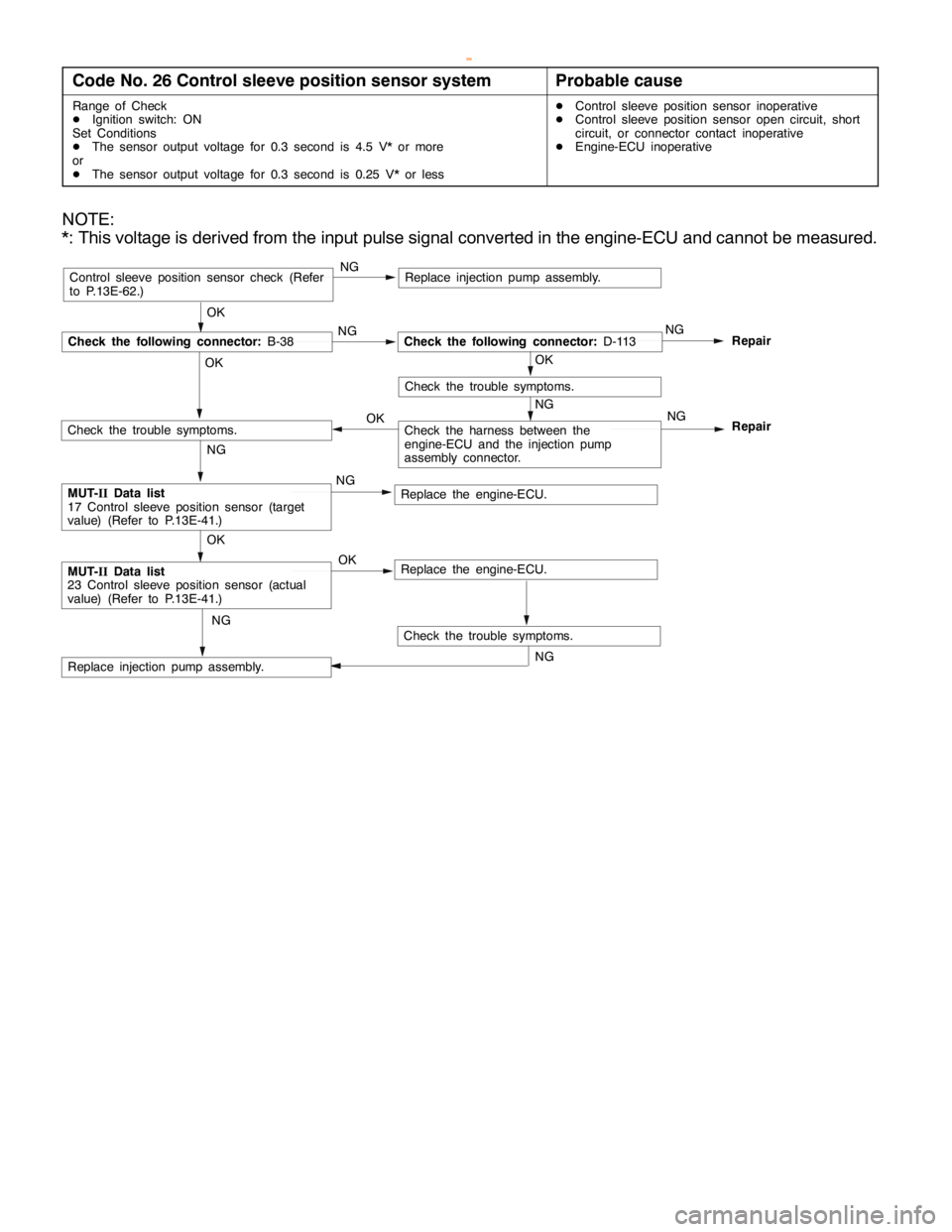
Code No. 26 Control sleeve position sensor systemProbable cause
Range of Check
DIgnition switch: ON
Set Conditions
DThe sensor output voltage for 0.3 second is 4.5 V* or more
or
DThe sensor output voltage for 0.3 second is 0.25 V* or lessDControl sleeve position sensor inoperative
DControl sleeve position sensor open circuit, short
circuit, or connector contact inoperative
DEngine-ECU inoperative
NOTE:
*: This voltage is derived from the input pulse signal converted in the engine-ECU and cannot be measured.
OK
NG
Check the following connector:D-113NG
Repair
OK
Repair
NGControl sleeve position sensor check (Refer
to P.13E-62.)
NG
NG OK
NG
Check the trouble symptoms.
Replace injection pump assembly.
Check the following connector:B-38
OK
Replace the engine-ECU.NGMUT-IIData list
17 Control sleeve position sensor (target
value) (Refer to P.13E-41.)
OK
Check the trouble symptoms.
Replace injection pump assembly.
Check the trouble symptoms.
NG
NG
Check the harness between the
engine-ECU and the injection pump
assembly connector.
MUT-IIData list
23 Control sleeve position sensor (actual
value) (Refer to P.13E-41.)Replace the engine-ECU. OK
www.WorkshopManuals.co.uk
Purchased from www.WorkshopManuals.co.uk
Page 629 of 1839
DIESEL FUEL <4D5-stepIII>-Troubleshooting13E-19
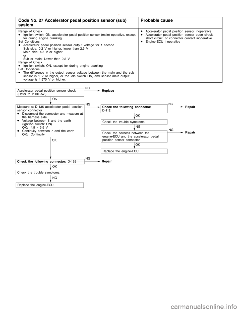
Code No. 27 Accelerator pedal position sensor (sub)
systemProbable cause
Range of Check
DIgnition switch: ON, accelerator pedal position sensor (main) operative, except
for during engine cranking
Set Conditions
DAccelerator pedal position sensor output voltage for 1 second
Sub side: 0.2 V or higher, lower than 2.5 V
Main side: 4.5 V or higher
or
Sub or main: Lower than 0.2 V
Range of Check
DIgnition switch: ON, except for during engine cranking
Set Conditions
DThe difference in the output sensor voltage between the main and the sub
sensor is 1 V or higher, or the idle switch ON, and sensor main output
voltage is 1.875 V or higher.DAccelerator pedal position sensor inoperative
DAccelerator pedal position sensor open circuit,
short circuit, or connector contact inoperative
DEngine-ECU inoperative
OK
Measure at D-135 accelerator pedal position
sensor connector
DDisconnect the connector and measure at
the harness side.
DVoltage between 8 and the earth
(Ignition switch: ON)
OK:4.5 - 5.5 V
DContinuity between 7 and the earth
OK:ContinuityNGNG
Repair
OK
OKRepair
NGAccelerator pedal position sensor check
(Refer to P.13E-57.)
NG
Replace the engine-ECU.OKNG
OK
Replace
NG
Check the trouble symptoms.
NG
RepairCheck the following connector:D-135
Check the harness between the
engine-ECU and the accelerator pedal
position sensor connector.
Check the trouble symptoms.
Replace the engine-ECU.
Check the following connector:
D-112
www.WorkshopManuals.co.uk
Purchased from www.WorkshopManuals.co.uk
Page 630 of 1839
DIESEL FUEL <4D5-stepIII>-Troubleshooting13E-20
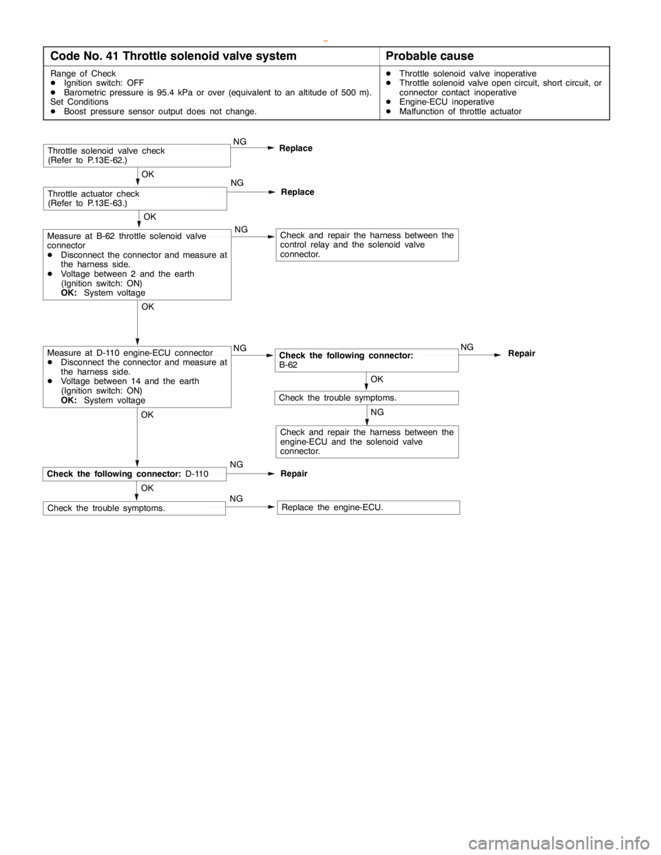
Code No. 41 Throttle solenoid valve systemProbable cause
Range of Check
DIgnition switch: OFF
DBarometric pressure is 95.4 kPa or over (equivalent to an altitude of 500 m).
Set Conditions
DBoost pressure sensor output does not change.DThrottle solenoid valve inoperative
DThrottle solenoid valve open circuit, short circuit, or
connector contact inoperative
DEngine-ECU inoperative
DMalfunction of throttle actuator
Check and repair the harness between the
engine-ECU and the solenoid valve
connector.
NG
OK
Check the trouble symptoms.
OK
Check and repair the harness between the
control relay and the solenoid valve
connector. NG
OKMeasure at B-62 throttle solenoid valve
connector
DDisconnect the connector and measure at
the harness side.
DVoltage between 2 and the earth
(Ignition switch: ON)
OK:System voltage
OK
Replace
Throttle actuator check
(Refer to P.13E-63.)NG
OK
Throttle solenoid valve check
(Refer to P.13E-62.)
Replace the engine-ECU. OK
RepairCheck the following connector:D-110
Check the trouble symptoms.NGReplace NG
Check the following connector:
B-62NG
RepairNGMeasure at D-110 engine-ECU connector
DDisconnect the connector and measure at
the harness side.
DVoltage between 14 and the earth
(Ignition switch: ON)
OK:System voltage
NG
www.WorkshopManuals.co.uk
Purchased from www.WorkshopManuals.co.uk
Page 633 of 1839
DIESEL FUEL <4D5-stepIII>-Troubleshooting13E-23
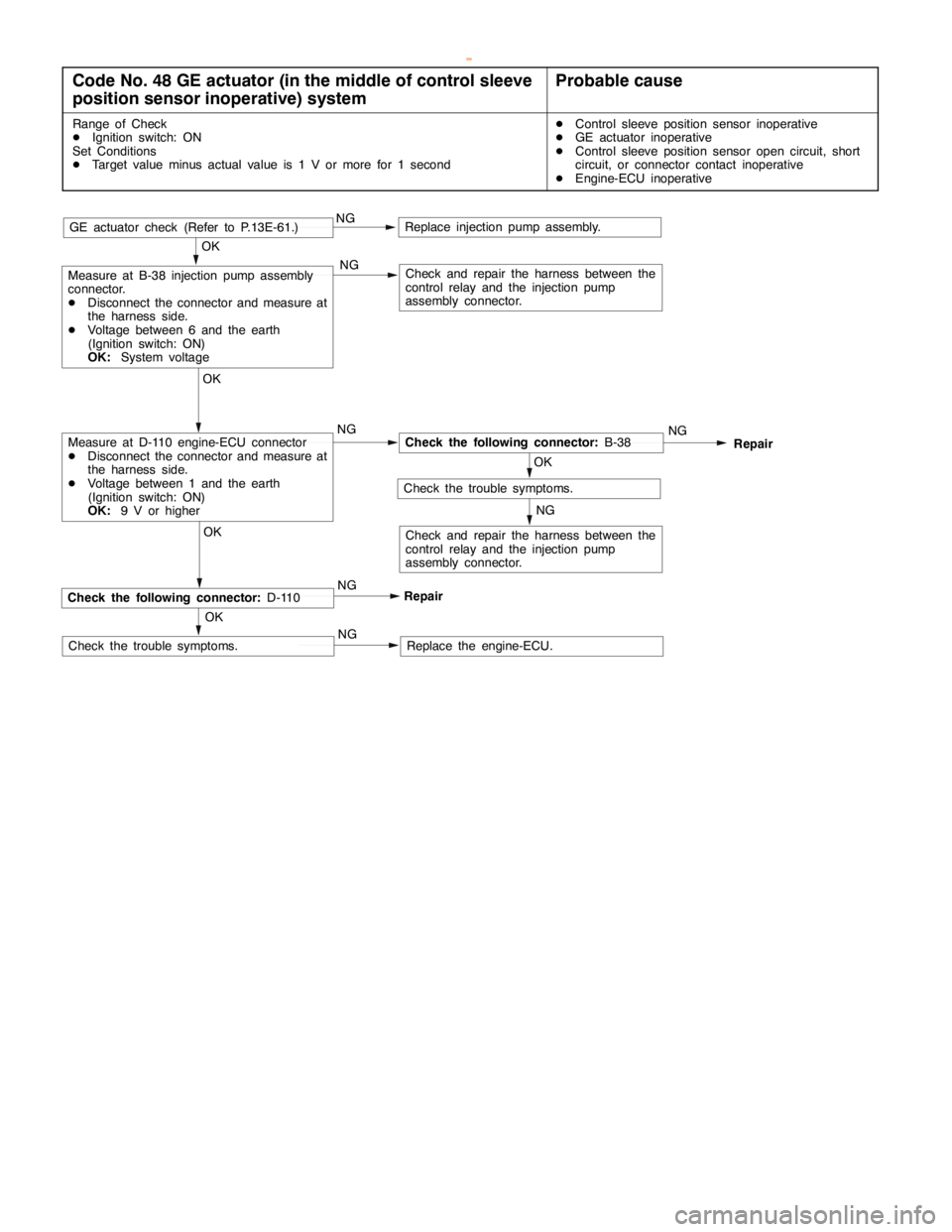
Code No. 48 GE actuator (in the middle of control sleeve
position sensor inoperative) systemProbable cause
Range of Check
DIgnition switch: ON
Set Conditions
DTarget value minus actual value is 1 V or more for 1 secondDControl sleeve position sensor inoperative
DGE actuator inoperative
DControl sleeve position sensor open circuit, short
circuit, or connector contact inoperative
DEngine-ECU inoperative
OK
OK
Check and repair the harness between the
control relay and the injection pump
assembly connector.
GE actuator check (Refer to P.13E-61.)
Replace the engine-ECU. OK
RepairCheck the following connector:D-110
Check the trouble symptoms.NGNG NG
Check the following connector:B-38NG
Repair
OK
Check the trouble symptoms.
NG
NGMeasure at D-110 engine-ECU connector
DDisconnect the connector and measure at
the harness side.
DVoltage between 1 and the earth
(Ignition switch: ON)
OK:9 V or higherOK
Measure at B-38 injection pump assembly
connector.
DDisconnect the connector and measure at
the harness side.
DVoltage between 6 and the earth
(Ignition switch: ON)
OK:System voltage
Replace injection pump assembly.
Check and repair the harness between the
control relay and the injection pump
assembly connector.
NG
www.WorkshopManuals.co.uk
Purchased from www.WorkshopManuals.co.uk
Page 634 of 1839
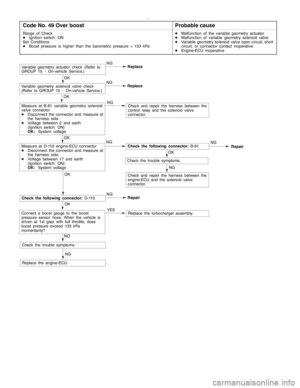
DIESEL FUEL <4D5-stepIII>-Troubleshooting13E-24
Code No. 49 Over boostProbable cause
Range of Check
DIgnition switch: ON
Set Conditions
DBoost pressure is higher than the barometric pressure + 133 kPaDMalfunction of the variable geometry actuator
DMalfunction of variable geometry solenoid valve
DVariable geometry solenoid valve open circuit, short
circuit, or connector contact inoperative
DEngine-ECU inoperative
OKOK
Check and repair the harness between the
control relay and the solenoid valve
connector.
Replace the engine-ECU.OK
ReplaceVariable geometry solenoid valve check
(Refer to GROUP 15 - On-vehicle Service.)
Check the trouble symptoms.NG
NG
Check the following connector:B-61NG
Repair
OK
Check the trouble symptoms.
NG
NGMeasure at D-110 engine-ECU connector
DDisconnect the connector and measure at
the harness side.
DVoltage between 17 and earth
(Ignition switch: ON)
OK:System voltageOK
Measure at B-61 variable geometry solenoid
valve connector
DDisconnect the connector and measure at
the harness side.
DVoltage between 2 and earth
(Ignition switch: ON)
OK:System voltage
Check and repair the harness between the
engine-ECU and the solenoid valve
connector.
ReplaceVariable geometry actuator check (Refer to
GROUP 15 - On-vehicle Service.)NG
OK
Repair
Check the following connector:D-110NG
NG
Replace the turbocharger assembly. YESConnect a boost gauge to the boost
pressure sensor hose. When the vehicle is
driven at 1st gear with full throttle, does
boost pressure exceed 133 kPa
momentarily?
NO
www.WorkshopManuals.co.uk
Purchased from www.WorkshopManuals.co.uk
Page 635 of 1839
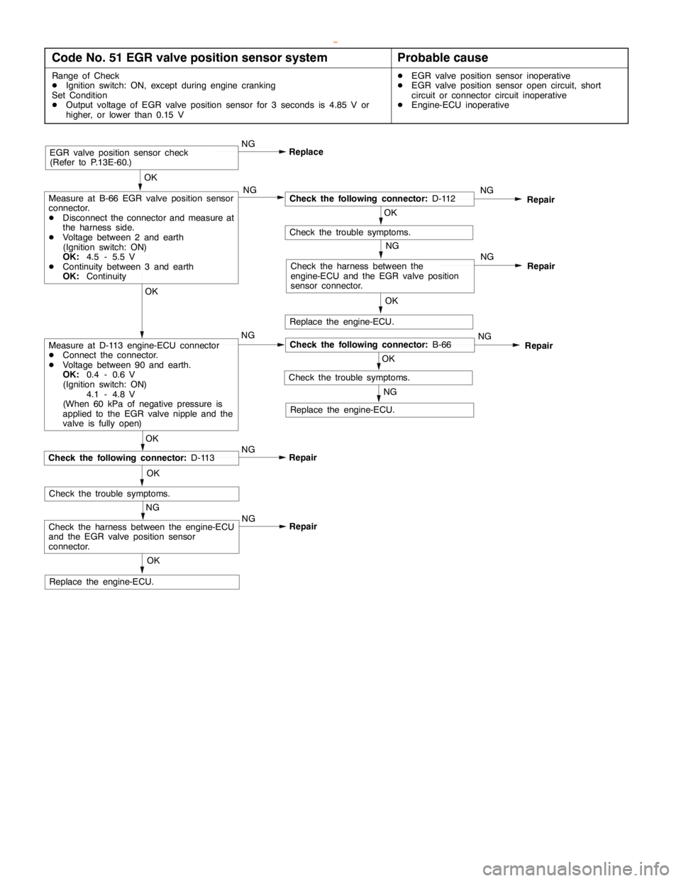
DIESEL FUEL <4D5-stepIII>-Troubleshooting13E-25
Code No. 51 EGR valve position sensor systemProbable cause
Range of Check
DIgnition switch: ON, except during engine cranking
Set Condition
DOutput voltage of EGR valve position sensor for 3 seconds is 4.85 V or
higher, or lower than 0.15 VDEGR valve position sensor inoperative
DEGR valve position sensor open circuit, short
circuit or connector circuit inoperative
DEngine-ECU inoperative
Repair NG
NG
OK
Check the harness between the engine-ECU
and the EGR valve position sensor
connector.
Replace the engine-ECU.
Repair NG
OK
NG
Repair
OK
OK
Check the harness between the
engine-ECU and the EGR valve position
sensor connector.
EGR valve position sensor check
(Refer to P.13E-60.)
OKReplace
Check the following connector:D-113
Check the trouble symptoms.NG
NG
Check the following connector:B-66NG
Repair
OK
Check the trouble symptoms.
NG
NGMeasure at D-113 engine-ECU connector
DConnect the connector.
DVoltage between 90 and earth.
OK:0.4 - 0.6 V
(Ignition switch: ON)
4.1 - 4.8 V
(When 60 kPa of negative pressure is
applied to the EGR valve nipple and the
valve is fully open)OK
Measure at B-66 EGR valve position sensor
connector.
DDisconnect the connector and measure at
the harness side.
DVoltage between 2 and earth
(Ignition switch: ON)
OK:4.5 - 5.5 V
DContinuity between 3 and earth
OK:Continuity
Replace the engine-ECU.
Replace the engine-ECU.
Check the following connector:D-112NG
Repair
OK
Check the trouble symptoms.
NG
www.WorkshopManuals.co.uk
Purchased from www.WorkshopManuals.co.uk
Page 636 of 1839
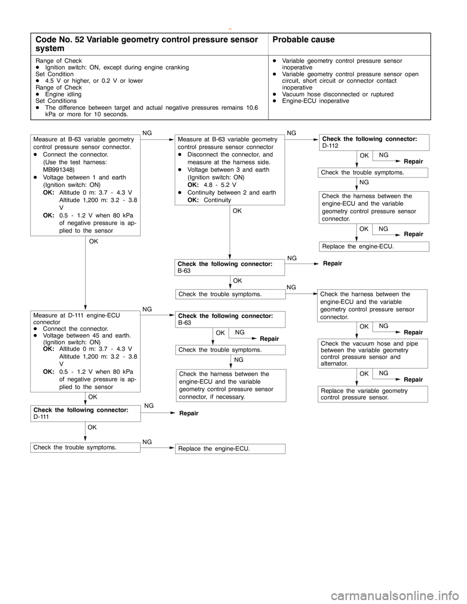
DIESEL FUEL <4D5-stepIII>-Troubleshooting13E-26
Code No. 52 Variable geometry control pressure sensor
systemProbable cause
Range of Check
DIgnition switch: ON, except during engine cranking
Set Condition
D4.5 V or higher, or 0.2 V or lower
Range of Check
DEngine idling
Set Conditions
DThe difference between target and actual negative pressures remains 10.6
kPa or more for 10 seconds.DVariable geometry control pressure sensor
inoperative
DVariable geometry control pressure sensor open
circuit, short circuit or connector contact
inoperative
DVacuum hose disconnected or ruptured
DEngine-ECU inoperative
NGReplace the engine-ECU.
Check the harness between the
engine-ECU and the variable
geometry control pressure sensor
connector, if necessary.
NG
Check the trouble symptoms.OK
NG
Repair
Replace the variable geometry
control pressure sensor.OK
NG
Repair
Check the vacuum hose and pipe
between the variable geometry
control pressure sensor and
alternator.OK
NG
Repair
NG
NG
Check the trouble symptoms.OK
Repair
Check the trouble symptoms.
OK
Replace the engine-ECU.OK
Repair NG NG
Check the harness between the
engine-ECU and the variable
geometry control pressure sensor
connector.
Check the trouble symptoms.OK
NG
Repair
Check the following connector:
D-111NG
Repair
OK
OKOK
Check the following connector:
B-63NG
NGNG
Check the following connector:
B-63
Measure at B-63 variable geometry
control pressure sensor connector.
DConnect the connector.
(Use the test harness:
MB991348)
DVoltage between 1 and earth
(Ignition switch: ON)
OK:Altitude 0 m: 3.7 - 4.3 V
Altitude 1,200 m: 3.2 - 3.8
V
OK:0.5 - 1.2 V when 80 kPa
of negative pressure is ap-
plied to the sensor
Measure at D-111 engine-ECU
connector
DConnect the connector.
DVoltage between 45 and earth.
(Ignition switch: ON)
OK:Altitude 0 m: 3.7 - 4.3 V
Altitude 1,200 m: 3.2 - 3.8
V
OK:0.5 - 1.2 V when 80 kPa
of negative pressure is ap-
plied to the sensor
Measure at B-63 variable geometry
control pressure sensor connector
DDisconnect the connector, and
measure at the harness side.
DVoltage between 3 and earth
(Ignition switch: ON)
OK:4.8 - 5.2 V
DContinuity between 2 and earth
OK:ContinuityCheck the following connector:
D-112
Check the harness between the
engine-ECU and the variable
geometry control pressure sensor
connector.
www.WorkshopManuals.co.uk
Purchased from www.WorkshopManuals.co.uk
Page 640 of 1839
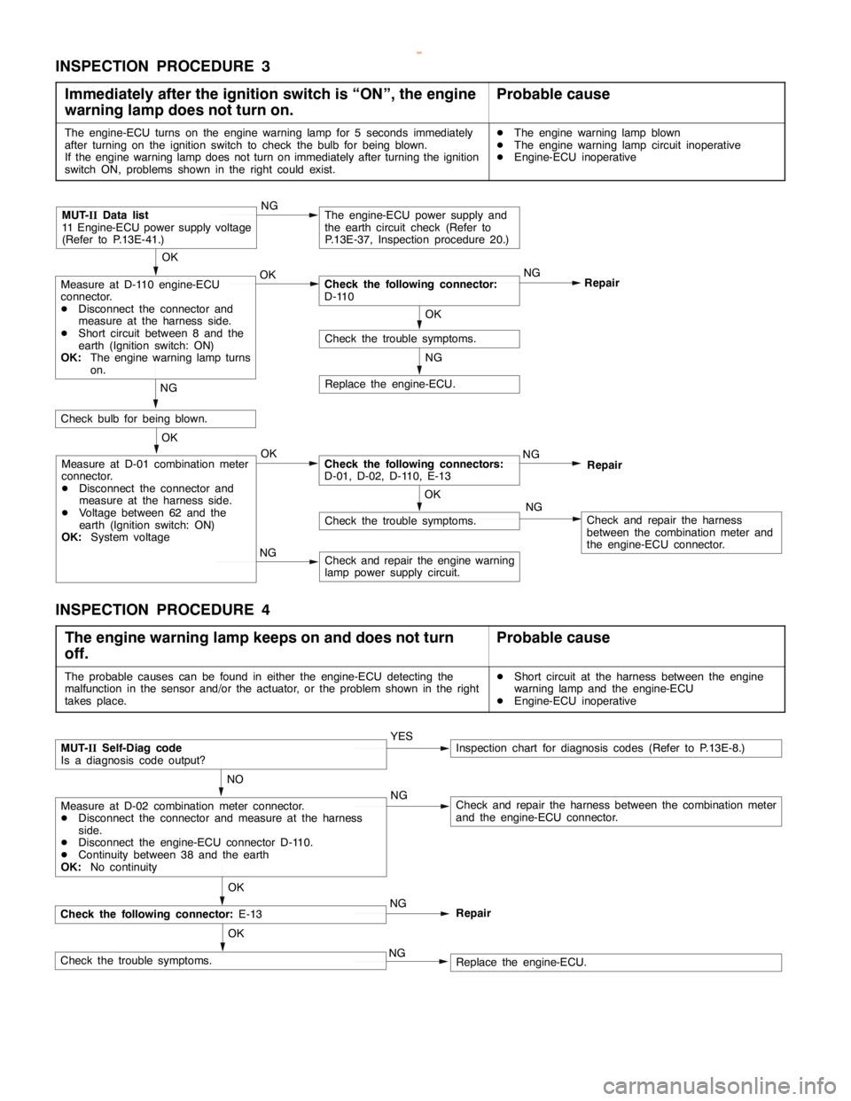
DIESEL FUEL <4D5-stepIII>-Troubleshooting13E-30
INSPECTION PROCEDURE 3
Immediately after the ignition switch is “ON”, the engine
warning lamp does not turn on.
Probable cause
The engine-ECU turns on the engine warning lamp for 5 seconds immediately
after turning on the ignition switch to check the bulb for being blown.
If the engine warning lamp does not turn on immediately after turning the ignition
switch ON, problems shown in the right could exist.DThe engine warning lamp blown
DThe engine warning lamp circuit inoperative
DEngine-ECU inoperative
NG
Replace the engine-ECU.
NG
Check and repair the harness
between the combination meter and
the engine-ECU connector.
NG
Check and repair the engine warning
lamp power supply circuit.
OK
Check the trouble symptoms.
OK
Measure at D-01 combination meter
connector.
DDisconnect the connector and
measure at the harness side.
DVoltage between 62 and the
earth (Ignition switch: ON)
OK:System voltageOKCheck the following connectors:
D-01, D-02, D-110, E-13NG
Repair
NG
Check bulb for being blown.
OK
Check the trouble symptoms.
OK
Measure at D-110 engine-ECU
connector.
DDisconnect the connector and
measure at the harness side.
DShort circuit between 8 and the
earth (Ignition switch: ON)
OK:The engine warning lamp turns
on.OKCheck the following connector:
D-110NG
Repair
MUT-IIData list
11 Engine-ECU power supply voltage
(Refer to P.13E-41.)NGThe engine-ECU power supply and
the earth circuit check (Refer to
P.13E-37, Inspection procedure 20.)
INSPECTION PROCEDURE 4
The engine warning lamp keeps on and does not turn
off.
Probable cause
The probable causes can be found in either the engine-ECU detecting the
malfunction in the sensor and/or the actuator, or the problem shown in the right
takes place.DShort circuit at the harness between the engine
warning lamp and the engine-ECU
DEngine-ECU inoperative
Check the following connector:E-13
NO
Measure at D-02 combination meter connector.
DDisconnect the connector and measure at the harness
side.
DDisconnect the engine-ECU connector D-110.
DContinuity between 38 and the earth
OK:No continuityNGCheck and repair the harness between the combination meter
and the engine-ECU connector.
OK
MUT-IISelf-Diag code
Is a diagnosis code output?YESInspection chart for diagnosis codes (Refer to P.13E-8.)
Check the trouble symptoms.OKReplace the engine-ECU. NGNG
Repair
www.WorkshopManuals.co.uk
Purchased from www.WorkshopManuals.co.uk
Page 646 of 1839
DIESEL FUEL <4D5-stepIII>-Troubleshooting13E-36
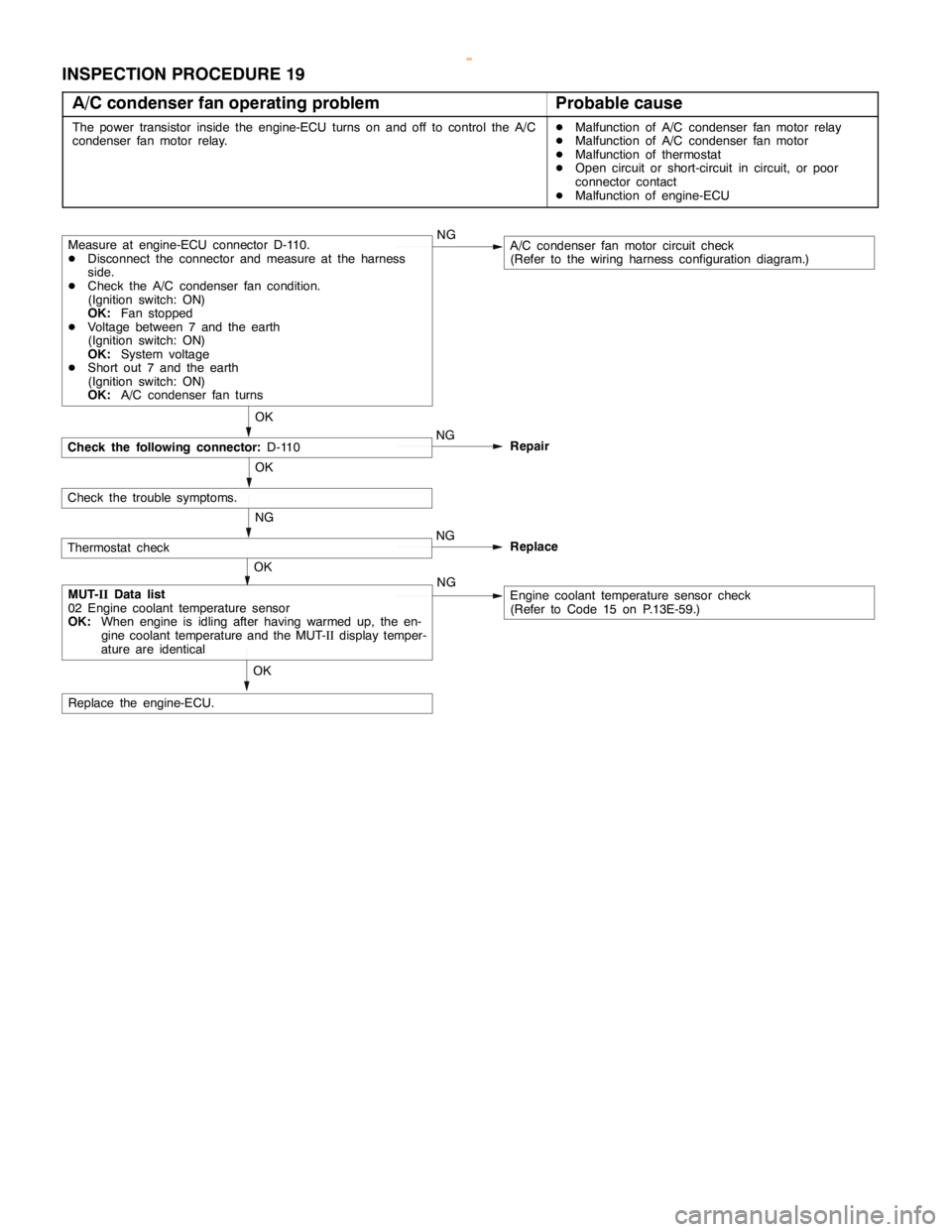
INSPECTION PROCEDURE 19
A/C condenser fan operating problem
Probable cause
The power transistor inside the engine-ECU turns on and off to control the A/C
condenser fan motor relay.DMalfunction of A/C condenser fan motor relay
DMalfunction of A/C condenser fan motor
DMalfunction of thermostat
DOpen circuit or short-circuit in circuit, or poor
connector contact
DMalfunction of engine-ECU
Check the following connector:D-110
OK
Measure at engine-ECU connector D-110.
DDisconnect the connector and measure at the harness
side.
DCheck the A/C condenser fan condition.
(Ignition switch: ON)
OK:Fan stopped
DVoltage between 7 and the earth
(Ignition switch: ON)
OK:System voltage
DShort out 7 and the earth
(Ignition switch: ON)
OK:A/C condenser fan turnsNGA/C condenser fan motor circuit check
(Refer to the wiring harness configuration diagram.)
OK
MUT-IIData list
02 Engine coolant temperature sensor
OK:When engine is idling after having warmed up, the en-
gine coolant temperature and the MUT-IIdisplay temper-
ature are identicalNGEngine coolant temperature sensor check
(Refer to Code 15 on P.13E-59.)
Check the trouble symptoms.OK
Replace the engine-ECU.NG
Repair
Thermostat checkNG
NGReplace
OK
www.WorkshopManuals.co.uk
Purchased from www.WorkshopManuals.co.uk