sensor MITSUBISHI MONTERO 2000 Service Repair Manual
[x] Cancel search | Manufacturer: MITSUBISHI, Model Year: 2000, Model line: MONTERO, Model: MITSUBISHI MONTERO 2000Pages: 1839, PDF Size: 29.19 MB
Page 804 of 1839

17-2
EVAPORATIVE EMISSION CONTROL
SYSTEM 36..............................
General Information 36......................
System Diagram 36.........................
Component Location 36......................
Purge Control System Check 37..............
Purge Port Vacuum Check 37................
Purge Control Solenoid Valve Check 38.......
EXHAUST GAS RECIRCULATION (EGR)
SYSTEM 39..............................
General Information 39......................
Operation 39................................
System Diagram 39.........................
Component Location 39......................
Exhaust Gas Recirculation (EGR) Control
System Check 40...........................
EGR Valve (Stepper Motor) Check 40........
EGR VALVE 42...........................
CANISTER 43............................
CATALYTIC CONVERTER 44..............
General Information 44......................
EMISSION CONTROL SYSTEM
<4D5> 45.............................
GENERAL INFORMATION 45..............
SERVICE SPECIFICATIONS 45............
SEALANT 45.............................
SPECIAL TOOL 45.......................
EXHAUST GAS RECIRCULATION (EGR)
SYSTEM 46..............................
General Information 46......................
System Diagram 46.........................
Component Location 46......................
Function Check 47..........................
EGR Solenoid Valve Operation Check 47.....
EGR Solenoid Valve Resistance Check 48....
Lever Position Sensor (LPS) Adjustment 48...
Engine Speed Sensor Check 49..............
Engine Coolant Temperature Sensor
Check 49...................................
CHECK AT THE GLOW & EGR CONTROL
UNIT 51..................................
EMISSION CONTROL SYSTEM
<4M4-VEHICLES WITH EGR> 52........
GENERAL INFORMATION 52..............
SERVICE SPECIFICATIONS 52............
EXHAUST GAS RECIRCULATION (EGR)
SYSTEM 53..............................
General Information 53......................
System Diagram 53.........................
Component Location 53......................
Function Check 54..........................
EGR Solenoid Valve Operation Check 54.....
EGR Solenoid Valve Resistance Check 55....
Accelerator Pedal Position Sensor (APS),
Engine Coolant Temperature Sensor, Intake
Air Temperature Sensor, Fuel Temperature
Sensor Check 55............................
Check at Engine-ECU 55....................
CATALYTIC CONVERTER 55..............
General Information 55......................
www.WorkshopManuals.co.uk
Purchased from www.WorkshopManuals.co.uk
Page 814 of 1839
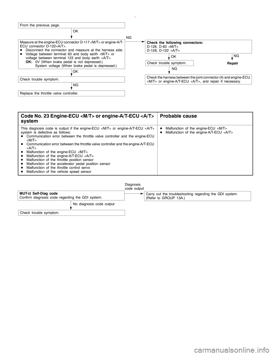
ENGINE AND EMISSION CONTROL -Auto-cruise Control System17-12
NG
Check the harness between the joint connector (4) and engine-ECU
NG
Repair
OK
Check trouble symptom.
From the previous page.
OK
Check the following connectors:
D-128, D-63
D-128, D-122
OK
Check trouble symptom.
NG
Replace the throttle valve controller.NG
Measure at the engine-ECU connector D-117
ECU connector D-122.
DDisconnect the connector and measure at the harness side.
DVoltage between terminal 63 and body earth
voltage between terminal 123 and body earth
OK:0V (When brakepedal is not depressed.)
System voltage (When brakepedal is depressed.)
Code No. 23 Engine-ECU
systemProbable cause
This diagnosis code is output if the engine-ECU
system is defective as follows:
DCommunication error between the throttle valve controller and the engine-ECU
DCommunication error between the throttle valve controller and the engine-A/T-ECU
DMalfunction of the engine-ECU
DMalfunction of the engine-A/T-ECU
DMalfunction of the throttle position sensor
DMalfunction of the accelerator pedal positionsensor
DMalfunction of the throttle control servo
DMalfunction of the vehicle speed sensorDMalfunction of the engine-ECU
DMalfunction of the engine-A/T-ECU
MUT-
IISelf-Diag code
Confirm diagnosis code regarding the GDI system.Diagnosis
code outputCarry out the troubleshooting regarding the GDI system.
(Refer to GROUP 13A.)
No diagnosis code output
Check trouble symptom.
www.WorkshopManuals.co.uk
Purchased from www.WorkshopManuals.co.uk
Page 816 of 1839
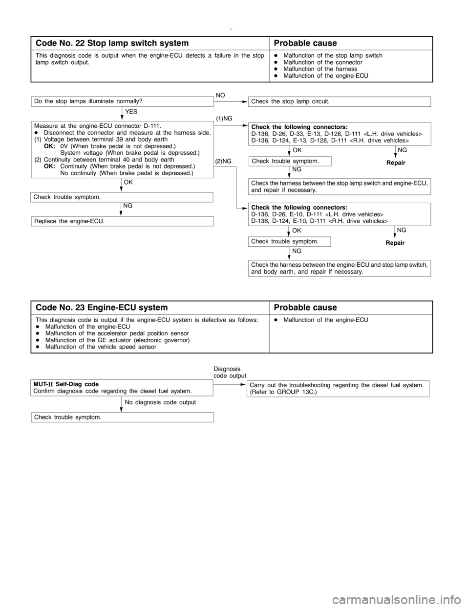
ENGINE AND EMISSION CONTROL -Auto-cruise Control System17-14
Code No. 22 Stop lamp switch systemProbable cause
This diagnosis code is output when the engine-ECU detects a failure in the stop
lampswitch output.DMalfunction of the stoplampswitch
DMalfunction of the connector
DMalfunction of the harness
DMalfunction of the engine-ECU
(2)NG
NG
Check the harness between the engine-ECU and stoplampswitch,
and body earth, and repair if necessary.
NG
Repair
OK
Check trouble symptom.
Measure at the engine-ECU connector D-111.
DDisconnect the connector and measure at the harness side.
(1) Voltage between terminal 39 and body earth
OK:0V (When brakepedal is not depressed.)
System voltage (When brakepedal is depressed.)
(2) Continuity between terminal 40 and body earth
OK:Continuity (When brakepedal is not depressed.)
No continuity (When brakepedal is depressed.)NO
Do the stop lamps illuminate normally?
OK
Check trouble symptom.
Check the following connectors:
D-136, D-26, D-33, E-13, D-128, D-111
D-136, D-124, E-13, D-128, D-111
OK
Check trouble symptom.
NG
Check the harness between the stoplampswitch and engine-ECU,
and repair if necessary.NG
Repair
Check the stoplampcircuit.
YES
(1)NG
Check the following connectors:
D-136, D-26, E-10, D-111
D-136, D-124, E-10, D-111
Replace the engine-ECU.
Code No. 23 Engine-ECU systemProbable cause
This diagnosis code is output if the engine-ECU system is defective as follows:
DMalfunction of the engine-ECU
DMalfunction of the accelerator pedal positionsensor
DMalfunction of the GE actuator (electronic governor)
DMalfunction of the vehicle speed sensorDMalfunction of the engine-ECU
MUT-
IISelf-Diag code
Confirm diagnosis code regarding the diesel fuel system.Diagnosis
code outputCarry out the troubleshooting regarding the diesel fuel system.
(Refer to GROUP 13C.)
No diagnosis code output
Check trouble symptom.
www.WorkshopManuals.co.uk
Purchased from www.WorkshopManuals.co.uk
Page 820 of 1839
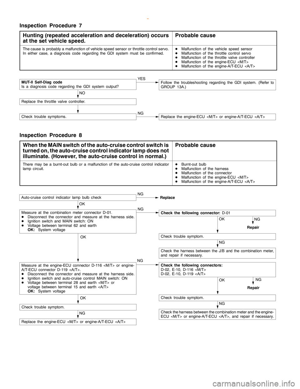
ENGINE AND EMISSION CONTROL -Auto-cruise Control System17-18
Inspection Procedure 7
Hunting (repeated acceleration and deceleration) occurs
at the set vehicle speed.
Probable cause
The cause is probably a malfunction of vehicle speed sensor or throttle control servo.
In either case, a diagnosis code regarding the GDI system must be confirmed.DMalfunction of the vehicle speed sensor
DMalfunction of the throttle control servo
DMalfunction of the throttle valve controller
DMalfunction of the engine-ECU
DMalfunction of the engine-A/T-ECU
MUT-II Self-Diag code
Is a diagnosis code regarding the GDI system output?YES
NO
Replace the throttle valve controller.
Check trouble symptoms.NGReplace the engine-ECU
Follow the troubleshooting regarding the GDI system. (Refer to
GROUP 13A.)
Inspection Procedure 8
When the MAIN switch of the auto-cruise control switch is
turned on, the auto-cruise control indicator lamp does not
illuminate. (However, the auto-cruise control in normal.)
Probable cause
There may be a burnt-out bulb or a malfunction of the auto-cruise control indicator
lampcircuit.DBurnt-out bulb
DMalfunction of the harness
DMalfunction of the connector
DMalfunction of the engine-ECU
DMalfunction of the engine-A/T-ECU
OK
Auto-cruise control indicatorlamp bulbcheckNG
Replace
NG
Repair
OK
NG
OK
Check trouble symptom.
NG
Check the harness between the J/B and the combination meter,
and repair if necessary.
Check the following connectors:
D-02, E-10, D-116
D-02, E-10, D-119
OK
Check trouble symptom.
NG
Repair
NG
Replace the engine-ECU
Measure at the engine-ECU connector D-116
A/T-ECU connector D-119 .
DDisconnect the connector and measure at the harness side.
DIgnition switch and auto-cruise control MAIN switch: ON
DVoltage between terminal 28 and earth
voltage between terminal 15 and earth
OK:System voltage
Measure at the combination meter connector D-01.
DDisconnect the connector and measure at the harness side.
DIgnition switch and MAIN switch: ON
DVoltage between terminal 62 and earth
OK:System voltageCheck the following connector:D-01
NG
Check the harness between the combination meter and the engine-
ECU
Check trouble symptom.
www.WorkshopManuals.co.uk
Purchased from www.WorkshopManuals.co.uk
Page 825 of 1839
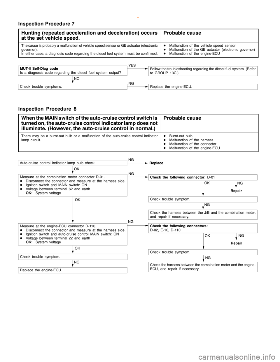
ENGINE AND EMISSION CONTROL -Auto-cruise Control System17-23
Inspection Procedure 7
Hunting (repeated acceleration and deceleration) occurs
at the set vehicle speed.
Probable cause
The cause is probably a malfunction of vehicle speed sensor or GE actuator (electronic
governor).
In either case, a diagnosis code regarding the diesel fuel system must be confirmed.DMalfunction of the vehicle speed sensor
DMalfunction of the GE actuator (electronic governor)
DMalfunction of the engine-ECU
MUT-II Self-Diag code
Is a diagnosis code regarding the diesel fuel system output?YES
NO
Check trouble symptoms.NGReplace the engine-ECU.
Follow the troubleshooting regarding the diesel fuel system. (Refer
to GROUP 13C.)
Inspection Procedure 8
When the MAIN switch of the auto-cruise control switch is
turned on, the auto-cruise control indicator lamp does not
illuminate. (However, the auto-cruise control in normal.)
Probable cause
There may be a burnt-out bulb or a malfunction of the auto-cruise control indicator
lampcircuit.DBurnt-out bulb
DMalfunction of the harness
DMalfunction of the connector
DMalfunction of the engine-ECU
OK
Auto-cruise control indicatorlamp bulbcheckNG
Replace
NG
Repair
OK
NG
OK
Check trouble symptom.
NG
Check the harness between the J/B and the combination meter,
and repair if necessary.
Check the following connectors:
D-02, E-10, D-110
OK
Check trouble symptom.
NG
Repair
NG
Replace the engine-ECU.NG
Measure at the engine-ECU connector D-110.
DDisconnect the connector and measure at the harness side.
DIgnition switch and auto-cruise control MAIN switch: ON
DVoltage between terminal 22 and earth
OK:System voltage
Measure at the combination meter connector D-01.
DDisconnect the connector and measure at the harness side.
DIgnition switch and MAIN switch: ON
DVoltage between terminal 62 and earth
OK:System voltageCheck the following connector:D-01
NG
Check the harness between the combination meter and the engine-
ECU, and repair if necessary. OK
Check trouble symptom.
www.WorkshopManuals.co.uk
Purchased from www.WorkshopManuals.co.uk
Page 827 of 1839

ENGINE AND EMISSION CONTROL -Auto-cruise Control System17-25
DATA LIST REFERENCE TABLE
For the data, which is input to the engine-ECU
<6G7-M/T, 4M4>, engine-A/T-ECU <6G7-A/T> andthrottle valve controller <6G7>, the following items
can be read out by using the MUT-II
.
HOW TO READ OUT DATA LIST
1. Connect the MUT-II
to the 16-pin diagnosis
connector.
Caution
Turn off the ignition switch befor connecting
and disconnecting the MUT-II
.2. Turn the ignition switch to “ON” position.
3. Select “auto-cruise control” on the MUT-II
menu, and then read out the data list.
<6G7>
Terminal
No.Check itemCheck conditionsNormal condition
01Auto-cruiseMAINMAIN switch: ONON
control
switchMAIN switch: OFFOFF
02SETMAIN switch:SET switch: ONON
(COAST)ONSET switch: OFFOFF
03RESUMERESUME switch: ONON
(ACCEL)RESUME switch: OFFOFF
04CANCELCANCEL switch: ONON
CANCEL switch: OFFOFF
05Stop lamp switchBrake pedal: DepressedON
(for stop lamp circuit)Brake pedal: ReleasedOFF
06Stop lamp switchBrake pedal: DepressedOFF
(for auto-cruise control
circuit)
Brake pedal: ReleasedON
07Clutch switch
Brake pedal: ReleasedOFF
Inhibitor switchSelector lever: “N“, “P” positionON
Selector lever: Other than “N“, “P” positionOFF
08Accelerator switchAccelerator pedal: ReleasedON
(Idle position switch)Accelerator pedal: DepressedOFF
09Auto-cruise controlAuto-cruise control system: ActivatedON
systemAuto-cruise control system: Not activatedOFF
10Vehicle speed sensorRoad test the vehicleThe speedometer and
the MUT-IIdisplay the
same value.
www.WorkshopManuals.co.uk
Purchased from www.WorkshopManuals.co.uk
Page 828 of 1839

ENGINE AND EMISSION CONTROL -Auto-cruise Control System17-26
Terminal
No.Normal condition Check conditions Check item
11Throttle position sensorAccelerator pedal: Fully depressed450 - 800 mV
Accelerator pedal: DepressedThe more deeply the
pedal is depressed, the
higher value the MUT-
IIdisplay
Accelerator pedal: Release4,200 - 4,900 mV
12Accelerator pedalAccelerator pedal: Fully depressed985 - 1,085 mV
position sensorAccelerator pedal: DepressedThe more deeply the
pedal is depressed, the
higher value the MUT-
IIdisplay
Accelerator pedal: Release4,000 mV or more
<4M4>
Terminal
No.Check itemCheck conditionsNormal condition
01Auto-cruiseMAINMAIN switch: ONON
control
switchMAIN switch: OFFOFF
02SETMAIN switch:SET switch: ONON
(COAST)ONSET switch: OFFOFF
03RESUMERESUME switch: ONON
(ACCEL)RESUME switch: OFFOFF
04CANCELCANCEL switch: ONON
CANCEL switch: OFFOFF
05Stop lamp switchBrake pedal: DepressedON
(for stop lamp circuit)Brake pedal: ReleasedOFF
06Stop lamp switchBrake pedal: DepressedOFF
(for auto-cruise control
circuit)
Brake pedal: ReleasedON
07Clutch switch
Brake pedal: ReleasedOFF
Inhibitor switchSelector lever: “N”, “P” positionON
Selector lever: Other than “N”, “P” positionOFF
08Accelerator switchAccelerator pedal: ReleasedON
(Idle position switch)Accelerator pedal: DepressedOFF
09Auto-cruise controlAuto-cruise control system: ActivatedON
systemAuto-cruise control system: Not activatedOFF
www.WorkshopManuals.co.uk
Purchased from www.WorkshopManuals.co.uk
Page 833 of 1839

ENGINE AND EMISSION CONTROL -Emission Control System <6G7>17-31
EMISSION CONTROL SYSTEM <6G7>
GENERAL INFORMATION
The emission control system consists of the following subsystems:
DCrankcase emission control system
DEvaporative emission control system
DExhaust emission control system
ItemsNameSpecification
Crankcase emission
control systemPositive crankcase ventilation (PCV) valveVariable flow type
(Purpose: HC reduction)
Evaporative emission
control systemCanister
Purge control solenoid valveEquipped
Duty cycle type solenoid valve
(Purpose: HC reduction)
Exhaust emission
control systemAir-fuel ratio control device - GDI systemOxygen sensor feedback type
(Purpose: CO, HC, NOx reduction)
Exhaust gas recirculation system
DEGR valveEquipped
Stepper motor type
(Purpose: NOx reduction)
Catalytic converterMonolith type
(Purpose: CO, HC, NOx reduction)
EMISSION CONTROL DEVICE REFERENCE TABLE
Related partsCrankcase
emission
control
systemEvaporative
emission
control
systemAir/fuel
ratio
control
systemCatalytic
converterExhaust
gas
recirculation
systemReference
page
PCV valve´17-35
Purge control solenoid valve´17-38
GDI system component´´GROUP
13A
Catalytic converter´17-44
EGR valve´17-40
www.WorkshopManuals.co.uk
Purchased from www.WorkshopManuals.co.uk
Page 860 of 1839

ENGINE AND EMISSION CONTROL -EngineControlSystem/EmissionControl
System <4D5-Step III>17-2
ENGINE CONTROL SYSTEM
GENERAL
OUTLINE OF CHANGE
Electronic-controlled throttle valve system has been used instead of a conventional cable-type accelerator
mechanism <4D5>.
Its service procedure is the same as for previous models with 6G7 or 4M4 engine.
EMISSION CONTROL SYSTEM <4D5-STEP
III>
GENERAL
OUTLINE OF CHANGES
Some service procedures have been established as the following changes have been made due to the
compliance with the Emission Regulation Step III.
DAn electronic-controlled EGR valve and EGR cooler have been used.
DA catalytic converter has been added.
GENERAL INFORMATION
The electronically-controlled EGR system reduces
the level of exhaust gases (NO
x).
ItemsNameSpecification
Exhaust emission
control systemExhaust gas recirculation system
DEGR valve
DEGR solenoid valve No.1
DEGR solenoid valve No.2
DEGR valve position sensorElectronically-controlled EGR system
Single type
ON-OFF solenoid valve
ON-OFF solenoid valve
Variable resistor type
SERVICE SPECIFICATIONS
ItemsStandard value
EGR solenoid valve Nos. 1 and 2 resistance (at 20_C)Ω36 - 44
www.WorkshopManuals.co.uk
Purchased from www.WorkshopManuals.co.uk
Page 883 of 1839
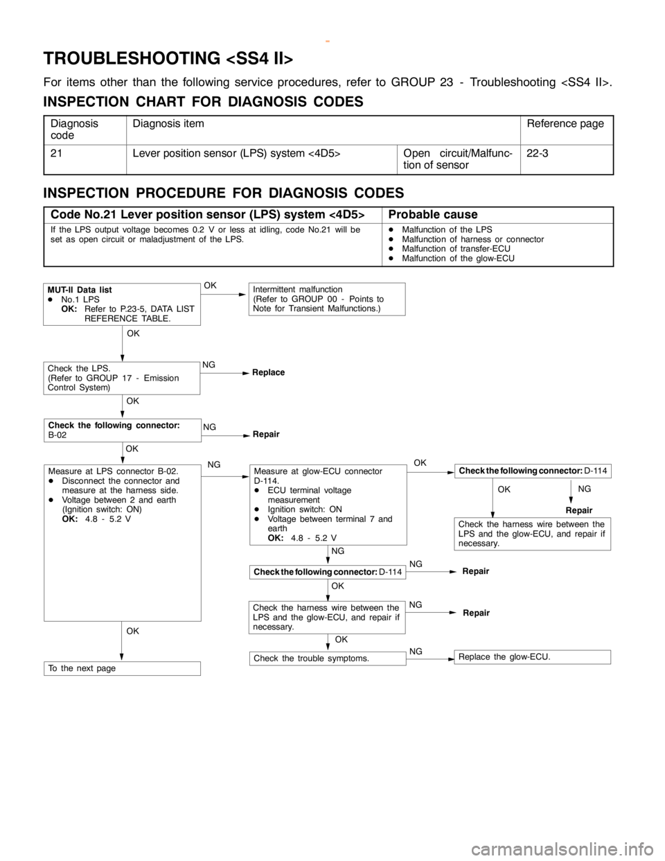
MANUAL TRANSMISSION -Troubleshooting
TROUBLESHOOTING
For items other than the following service procedures, refer to GROUP 23 - Troubleshooting
INSPECTION CHART FOR DIAGNOSIS CODES
Diagnosis
codeDiagnosis itemReference page
21Lever position sensor (LPS) system <4D5>Open circuit/Malfunc-
tion of sensor22-3
INSPECTION PROCEDURE FOR DIAGNOSIS CODES
Code No.21 Lever position sensor (LPS) system <4D5>Probable cause
If the LPS output voltage becomes 0.2 V or less at idling, code No.21 will be
set as opencircuit or maladjustment of the LPS.DMalfunction of the LPS
DMalfunction of harness or connector
DMalfunction of transfer-ECU
DMalfunction of the glow-ECU
NGOK
NG
Repair
MUT-II Data list
DNo.1 LPS
OK:Refer to P.23-5, DATA LIST
REFERENCE TABLE.
NG
ReplaceCheck the LPS.
(Refer to GROUP 17 - Emission
Control System)
OK
NG
Repair
OK
Check the following connector:
B-02
OK
OK
Check the following connector:D-114
Repair
NG
Repair
NG
Repair
OK
OK
Check the following connector:D-114
Measure at glow-ECU connector
D-114.
DECU terminal voltage
measurement
DIgnition switch: ON
DVoltage between terminal 7 and
earth
OK:4.8 - 5.2 V
NGNG
NGCheck the trouble symptoms.
OK
Measure at LPS connector B-02.
DDisconnect the connector and
measure at the harness side.
DVoltage between 2 and earth
(Ignition switch: ON)
OK:4.8 - 5.2 V
To the nextpage
Intermittent malfunction
(Refer to GROUP 00 - Points to
Note for Transient Malfunctions.)
OK
Check the harness wire between the
LPS and the glow-ECU, and repair if
necessary.
Check the harness wire between the
LPS and the glow-ECU, and repair if
necessary.
Replace the glow-ECU.
www.WorkshopManuals.co.uk
Purchased from www.WorkshopManuals.co.uk