MITSUBISHI MONTERO 2000 Service Repair Manual
MONTERO 2000
MITSUBISHI
MITSUBISHI
https://www.carmanualsonline.info/img/19/57331/w960_57331-0.png
MITSUBISHI MONTERO 2000 Service Repair Manual
Trending: oil temperature, compression ratio, remote control, CD player, air filter, bulb, heating
Page 451 of 1839
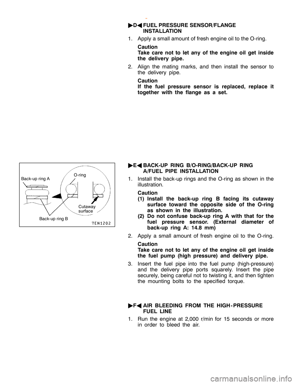
B
ack-u p rin g A O
-rin g B
ack-u p rin g B
w
ww.W ork sh opM an uals .c o .u k
P urc h ased f r o m w ww.W ork sh opM an uals .c o .u k
Page 452 of 1839
GDI -Injector13A-238
NOTE
When removing the fuel pump (high pressure), air may
get into the fuel pump (high pressure). If air gets into
the fuel pump (high pressure), diagnosis code No.56 for
abnormal fuel pressure will be output.
2. Use the MUT-IIto check the diagnosis code. If the
diagnosis code No.56 for fuel pressure sensor system
defect is output, erase it.
www.WorkshopManuals.co.uk
Purchased from www.WorkshopManuals.co.uk
Page 453 of 1839
F
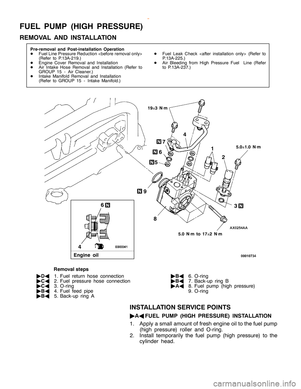
U EL PU M P (H IG H PR ESSU RE)
R EM OVA L AND IN STA LLA TIO N 4
5 6 7
9
6
4
Page 454 of 1839
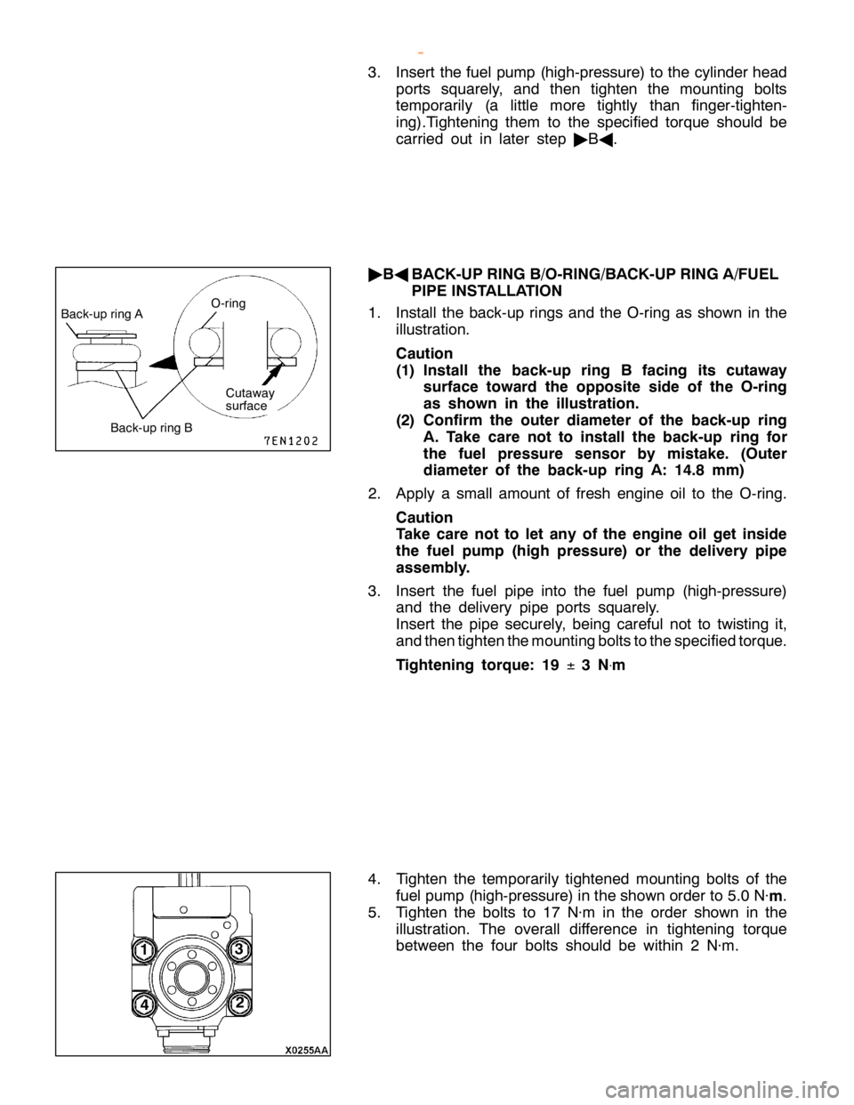
B
ack-u p rin g A O
-rin g B
ack-u p rin g B
Page 455 of 1839
GDI -Fuel Pump (High Pressure)13A-241
"
CA
O-RING/FUEL PRESSURE HOSE INSTALLATION
1. Apply a small amount of fresh engine oil to the O-ring.
Caution
Take care not to let any of the engine oil get inside
the fuel pump (high pressure) or the delivery pipe
assembly.
2. While being careful not to damage the O-ring, turn the
fuel pressure hose to the left and right and connect it
to the delivery pipe assembly. After connecting, check
that the fuel injector turns smoothly.
3. If the fuel pressure hose does not turn smoothly, the cause
may be that the O-ring is getting caught. Remove the fuel
pressure hose, check the O-ring for damage and
re-connect the fuel pressure hose to the delivery pipe
assembly and then re-check.
www.WorkshopManuals.co.uk
Purchased from www.WorkshopManuals.co.uk
Page 456 of 1839
T
H RO TTLE BO DY
R EM OVA L AND IN STA LLA TIO N 2
4 5
6
1 2
±1
N
×m
5 .0
±1
.0 N
×m
1 8
±2
N
×m
14
±1
N
×m
1 8
±2
N
×m
5
.0
±1
.0 N
×m
R em oval ste p s
1 . Thro ttle body sta y
2 . Thro ttle co ntr o l se rv o co nnecto r co n-
n ectio n
3 . Thro ttle posit io n se nso r co nnecto r
c o nnectio n 4
. W ate r hose co nnectio n
" BA
5. Thro ttle body asse m bly
" AA
6. Thro ttle body gaske t
I N STA LLA TIO N SER VIC E PO IN TS
" AA
TH RO TTLE BO DY GASK ET IN STA LLA TIO N
T he pro je ctio n on th e gaske t sh ould fa ce upw ard .
Page 457 of 1839
GDI -Throttle Body13A-243
"
BA
THROTTLE BODY INSTALLATION
If the throttle body is replaced, initialize the
electronic-controlled throttle valve system.
Initialization
Turn on the ignition switch, and turn it to the LOCK (OFF)
position within one second. Then leave it for at least ten
seconds with the ignition switch in the LOCK (OFF) position.
www.WorkshopManuals.co.uk
Purchased from www.WorkshopManuals.co.uk
Page 458 of 1839
R
esis ta nce va lu e ch anges
s m ooth ly in re sp onse to
t h ro ttle va lv e openin g angle .
Page 459 of 1839
I
N JE C TO R DRIV ER
R EM OVA L AND IN STA LLA TIO N
Page 460 of 1839
E
N G IN E
-E C U< M /T > ,E
N G IN E-
A /T -E C U< A/T > ,T
H RO TTLE VA LV E
C O NTR O LLE R
R EM OVA L AND IN STA LLA TIO N
Trending: wheel alignment, gas type, brake sensor, door lock, engine, recommended oil, wheel


