MITSUBISHI OUTLANDER SPORT 2014 3.G Owners Manual
Manufacturer: MITSUBISHI, Model Year: 2014, Model line: OUTLANDER SPORT, Model: MITSUBISHI OUTLANDER SPORT 2014 3.GPages: 384, PDF Size: 46.94 MB
Page 141 of 384
Tire pressure monitoring system 5-78 Features and controls
5
The tire pressure monitoring system may not work normally in the following circum- stances: A wireless facility or device using the same frequency is near the vehicle. Snow or ice is stuck inside the fenders and/or on the wheels. The tire inflation pressure sensor’s battery is dead.
Wheels other than Mitsubishi genuine wheels are being used. Wheels that are not fi
tted with tire infla-
tion pressure sensors are being used. Wheels whose ID codes are not memo- rized by the vehicle are used. Compact spare tire is fitted on a road wheel. A window tint that affects the radio wave signals is installed.
N00532901192
If new wheels with new tire inflation pressure sensors are installed, their ID codes must be programmed into the tire pressure monitoringsystem. Have the tire and wheel replacement performed by an authorized Mitsubishi Motors dealer to avoid the risk of damagingthe tire inflation pressure sensors. If the
wheel replacement is not done by an autho- rized Mitsubishi Motors dealer, it is not cov- ered by your warranty.
N00533001246
Your tire pressure monitoring system oper- ates on a radio frequency subject to Federal Communications Commission (FCC) Rules (For vehicles sold in U.S.A.) and IndustryCanada Rules (For vehicles sold in Canada). This device complies with part 15 of FCC Rules and Industry Canada licence-exemptRSS standard(s). Operation is subject to the following two con- ditions. This device may not cause harmful inter- ference. This device must accept any interference received, including interference that maycause undesired operation.
CAUTION If a tire has a puncture, replace that tire with the spare tire. Driving on a punctured tire could lead to an accident. The warning light/display may not illuminate immediately in the event of a tire blowout or rapid leak.NOTE
To avoid the risk of damage to the tire infla- tion pressure sensors, have any punctured tire repaired by an authorized Mitsubishi Motors dealer. If the tire repair is not done byan authorized Mitsubishi Motors dealer, it is not covered by your warranty. Do not use an aerosol puncture-repair spray on any tire. Such a spray could damage the tire inflationpressure sensors. Have any puncture repaired by an authorized Mitsubishi Motors dealer.
NOTE
Tire inflation pressures vary with the ambi- ent temperature. If the
vehicle is subjected to
large variations in ambient temperature, the tire inflation pressures may be under-inflated (causing the warning light/display to comeon) when the ambient temperature is rela- tively low. If the warning light/display comes on, adjust the tire inflation pressure.
Whenever the tires and wheels are replaced with new ones
CAUTION The use of non-genuine wheels will prevent the proper fit of the tire inflation pressure sensors, resulting air leakage or damage of the sensors.
General information
BK0202700US.bo
ok 78 ページ 2013年3月28日 木曜日 午前11時54分
Page 142 of 384
Rear-view camera (if so equipped)
Features and controls 5-79
5
N00546201183
When the gearshift lever or the selector lever is in the “R” position with the ignition switch or the operation mode is in ON, the rear-viewimage will be displayed on the screen of the Mitsubishi Multi-Communication System or the DISPLAY AUDIO in the center panel.When the gearshift lever or the selector lever is shifted out of the “R” position, the rear- view image will go off.
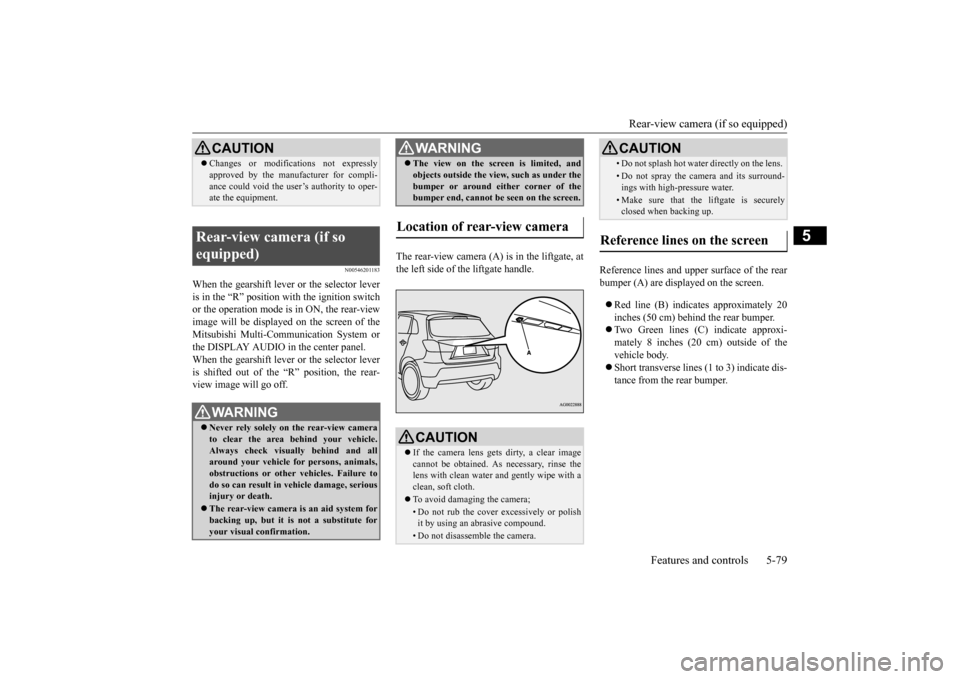
The rear-view camera (A) is in the liftgate, at the left side of the liftgate handle.
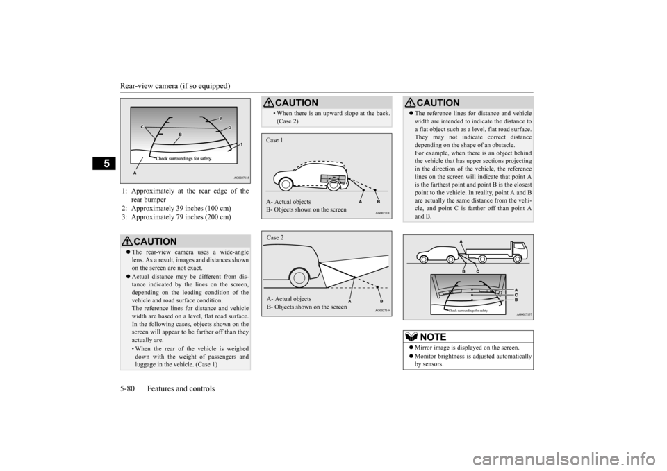
Reference lines and upper surface of the rear bumper (A) are displayed on the screen. Red line (B) indicates approximately 20 inches (50 cm) behind the rear bumper. Two Green lines (C) indicate approxi- mately 8 inches (20 cm) outside of the vehicle body. Short transverse lines (1 to 3) indicate dis- tance from the rear bumper.
CAUTION Changes or modifications not expressly approved by the manufacturer for compli- ance could void the user’s authority to oper- ate the equipment.
Rear-view camera (if so equipped)
WA R N I N G Never rely solely on the rear-view camera to clear the area behind your vehicle. Always check visually behind and all around your vehicle for persons, animals, obstructions or other vehicles. Failure todo so can result in vehicle damage, serious injury or death. The rear-view camera is an aid system for backing up, but it is not a substitute for your visual confirmation.
The view on the screen is limited, and objects outside the view, such as under the bumper or around either corner of the bumper end, cannot be seen on the screen.
Location of rear-view camera
CAUTION If the camera lens gets dirty, a clear image cannot be obtained. As necessary, rinse thelens with clean water and gently wipe with a clean, soft cloth. To avoid damaging the camera;• Do not rub the cover excessively or polish it by using an abrasive compound. • Do not disassemble the camera.WA R N I N G
• Do not splash hot water directly on the lens. • Do not spray the camera and its surround- ings with high-pressure water.• Make sure that the liftgate is securelyclosed when backing up.
Reference lines on the screen
CAUTION
BK0202700US.bo
ok 79 ページ 2013年3月28日 木曜日 午前11時54分
Page 143 of 384
Rear-view camera (if so equipped) 5-80 Features and controls
5
1: Approximately at the rear edge of the
rear bumper
2: Approximately 39 inches (100 cm) 3: Approximately 79 inches (200 cm)
CAUTION The rear-view camera uses a wide-angle lens. As a result, images and distances shownon the screen are not exact. Actual distance may be different from dis- tance indicated by the lines on the screen, depending on the loading condition of the vehicle and road surface condition.The reference lines for distance and vehicle width are based on a level, flat road surface. In the following cases, objects shown on thescreen will appear to be farther off than they actually are.• When the rear of the vehicle is weigheddown with the weight of passengers and luggage in the vehicle. (Case 1)
• When there is an upward slope at the back. (Case 2)CAUTION
Case 1 A- Actual objects B- Objects shown on the screenCase 2 A- Actual objects B- Objects shown on the screen
CAUTION The reference lines for distance and vehicle width are intended to indicate the distance to a flat object such as a level, flat road surface. They may not indicate correct distance depending on the shape of an obstacle.For example, when there is an object behind the vehicle that has upper sections projecting in the direction of the vehicle, the referencelines on the screen will indicate that point A is the farthest point a
nd point B is the closest
point to the vehicle. In reality, point A and Bare actually the same distance from the vehi- cle, and point C is farther off than point A and B.NOTE
Mirror image is displayed on the screen. Monitor brightness is adjusted automatically by sensors.
BK0202700US.bo
ok 80 ページ 2013年3月28日 木曜日 午前11時54分
Page 144 of 384
Instrument cluster
Features and controls 5-81
5
N00519000388
N00519100259
The speedometer shows the vehicle speed in miles per hour (mph) or kilometers per hour (km/h).
N00519200289
The tachometer shows engine revolutions perminute. This allows the driver to determinethe most efficient selector position and engine speed combinations. This gauge also assists in evaluating engineperformance.
On vehicles equipped with Mitsubishi Multi- Communication System, it is possible to change the display language of the screen. For details, please refer to the separated owner’s manual. Under certain circumstances, it may become difficult to see an image on the screen, evenwhen the system is functioning correctly. • In a dark area, such as at night. • When water drops or condensation are on the lens. • When sun light or headlights shine directly into the lens.
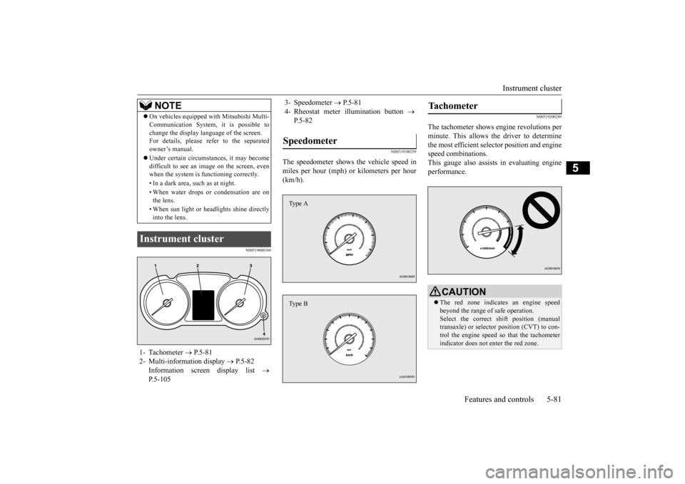
Instrument cluster 1- Tachometer
P.5-81
2- Multi-information display
P.5-82
Information screen display list
P.5-105NOTE
3- Speedometer
P.5-81
4- Rheostat meter illumination button
P.5-82
Speedometer Type AType B
Tachometer
CAUTION The red zone indicates an engine speed beyond the range of safe operation. Select the correct shift position (manual transaxle) or selector position (CVT) to con-trol the engine speed so that the tachometer indicator does not enter the red zone.
BK0202700US.bo
ok 81 ページ 2013年3月28日 木曜日 午前11時54分
Page 145 of 384
Multi-information display 5-82 Features and controls
5
N00554900195
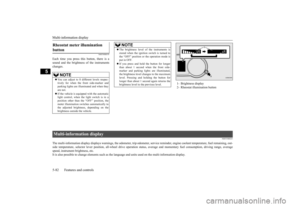
Each time you press this button, there is a sound and the brightness of the instruments changes.
N00555000265
The multi-information display displays warn
ings, the odometer, trip odometer, service re
minder, engine coolant temperature, fue
l remaining, out-
side temperature, selector lever position, all-wheel drive opera
tion status, average and momentar
y fuel consumption, driving ra
nge, average
speed, instrument brightness, etc. It is also possible to change elements such as th
e language and units used on the multi-information display.
Rheostat meter illumination button
NOTE
You can adjust to 8 different levels respec- tively for when the front side-marker and parking lights are illuminated and when they are not. If the vehicle is equipped with the automatic light control, when the light switch is in aposition other than the “OFF” position, the meter illumination switches automatically to the adjusted brightness, depending on thebrightness outside the vehicle.
The brightness level of the instruments is stored when the ignition switch is turned to the “OFF” position or the operation mode is put in OFF. If you press and hold the button for longer than about 1 second when the front side- marker and parking lights are illuminated,the brightness level changes to the maximum level. Pressing and holding the button for longer than about 1 second again returns thebrightness level to the previous level.NOTE
1- Brightness display 2- Rheostat illumination button
Multi-information display BK0202700US.bo
ok 82 ページ 2013年3月28日 木曜日 午前11時54分
Page 146 of 384
Multi-information display
Features and controls 5-83
5
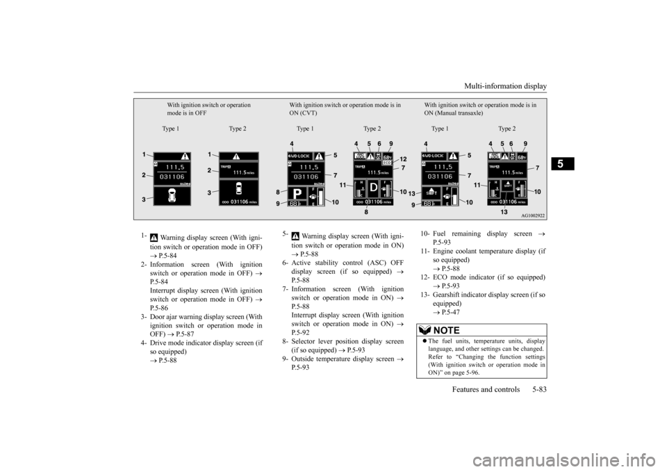
With ignition switch or operation mode is in OFF
With ignition switch or operation mode is in ON (CVT)
With ignition switch or
operation mode is in
ON (Manual transaxle)
Type 1 Type 2 Type 1 Type 2 Type 1 Type 2
1-
Warning display screen (With igni- tion switch or operation mode in OFF) P.5-84
2- Information screen (With ignition
switch or operation mode in OFF)
P.5-84 Interrupt display screen (With ignitionswitch or operation mode in OFF)
P.5-86
3- Door ajar warning display screen (With
ignition switch or operation mode in OFF)
P.5-87
4- Drive mode indicator display screen (if
so equipped) P.5-88
5-
Warning display screen (With igni- tion switch or operation mode in ON) P.5-88
6- Active stability control (ASC) OFF
display screen (if so equipped)
P.5-88
7- Information screen (With ignition
switch or operation mode in ON)
P.5-88 Interrupt display screen (With ignition switch or operation mode in ON)
P.5-92
8- Selector lever position display screen
(if so equipped)
P.5-93
9- Outside temperature display screen
P.5-93
10- Fuel remaining display screen
P.5-93
11- Engine coolant temperature display (if
so equipped) P.5-88
12- ECO mode indicator (if so equipped)
P.5-93
13- Gearshift indicator display screen (if so
equipped) P.5-47NOTE
The fuel units, temperature units, display language, and other settings can be changed.Refer to “Changing the function settings (With ignition switch or operation mode in ON)” on page 5-96.
BK0202700US.bo
ok 83 ページ 2013年3月28日 木曜日 午前11時54分
Page 147 of 384
Multi-information display 5-84 Features and controls
5
N00555100149
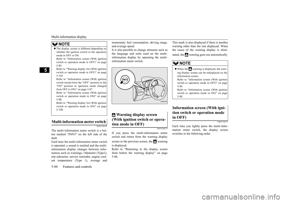
The multi-information meter switch is a but- ton marked “INFO” on the left side of thedash. Each time the multi-information meter switch is operated, a sound is emitted and the multi-information display changes between infor- mation such as warnings, Odometer (Type1), trip odometer, service reminder, engine cool-ant temperature (Type 1), average and
momentary fuel consumption, driving range, and average speed. It is also possible to change elements such as the language and units used on the multi-information display by operating the multi- information meter switch.
N00555200179
If you press the multi-information meter switch and return from the warning display screen to the previous screen, the warning is displayed. Refer to “Returning to the display screenfrom before the warning display” on page5-86.
This mark is also displayed if there is another warning other than the one displayed. When the cause of the warning display is elimi- nated, the warning goes out automatically.
N00555300167
Each time you lightly press the multi-infor- mation meter switch, the display screenswitches in the following order.
The display screen is different depending on whether the ignition switch or the operation mode in OFF or ON. Refer to “Information screen (With ignition switch or operation mode in OFF)” on page5-84. Refer to “Warning displa
y list (With ignition
switch or operation mode in OFF)” on page5-105. Refer to “Information screen (With ignition switch turned from the “OFF” position to the“ON” position or operation mode changed from OFF to ON)” on page 5-87. Refer to “Information screen (With ignitionswitch or operation mode in ON)” on page 5-88. Refer to “Warning displa
y list (With ignition
switch or operation mode in ON)” on page 5-108.
Multi-information meter switch
NOTE
Warning display screen (With ignition switch or opera- tion mode in OFF)
NOTE
When the warning is displayed, the warn- ing display screen can be redisplayed on the information screen.Refer to “Information screen (With ignition switch or operation mode in OFF)” on page 5-84.Refer to “Information screen (With ignition switch or operation mode in ON)” on page 5-88.
Information screen (With igni- tion switch or operation mode in OFF)
BK0202700US.bo
ok 84 ページ 2013年3月28日 木曜日 午前11時54分
Page 148 of 384
Multi-information display
Features and controls 5-85
5
N00555400113
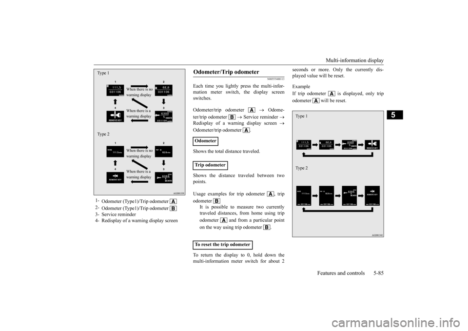
Each time you lightly press the multi-infor- mation meter switch, the display screenswitches. Odometer/trip odometer
Odome-
ter/trip odometer
Service reminder
Redisplay of a warning display screen
Odometer/trip odometer . Shows the total distance traveled. Shows the distance traveled between two points. To return the display to 0, hold down the multi-information meter switch for about 2
seconds or more. Only the currently dis- played value will be reset. Example If trip odometer is displayed, only tripodometer will be reset.
1-
Odometer (Type1)/Trip odometer
2-
Odometer (Type1)/Trip odometer
3- Service reminder4- Redisplay of a warning display screenTy p e 1
When there is no warning display When there is a warning display
Ty p e 2
When there is no warning display When there is a warning display
Odometer/Trip odometer Odometer Trip odometer Usage examples for trip odometer , trip odometer
It is possible to measure two currently traveled distances, from home using trip odometer and from a particular pointon the way using trip odometer . To reset the trip odometer
Ty p e 1 Ty p e 2
BK0202700US.bo
ok 85 ページ 2013年3月28日 木曜日 午前11時54分
Page 149 of 384
Multi-information display 5-86 Features and controls
5
N00555500042
Shows the distance and number of months until the next periodic inspection. Refer to “Service reminder” on page 5-94.
N00559600201
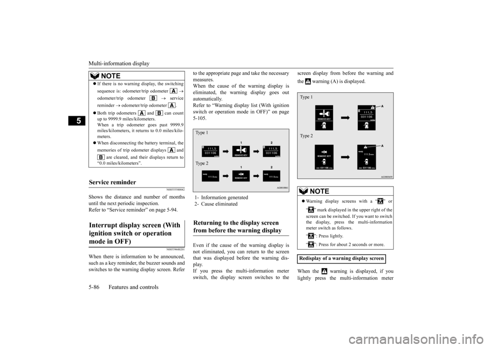
When there is information to be announced, such as a key reminder, the buzzer sounds andswitches to the warning display screen. Refer
to the appropriate page and take the necessary measures. When the cause of the warning display is eliminated, the warning display goes outautomatically. Refer to “Warning display list (With ignition switch or operation mode in OFF)” on page5-105. Even if the cause of the warning display is not eliminated, you can return to the screen that was displayed before the warning dis- play.If you press the multi-information meter switch, the display screen switches to the
screen display from before the warning and the warning (A) is displayed. When the warning is displayed, if you lightly press the multi-information meter
NOTE
If there is no warning display, the switching sequence is: odometer/trip odometer
odometer/trip odometer
service
reminder
odometer/trip odometer .
Both trip odometers and can count up to 9999.9 miles/kilometers. When a trip odometer goes past 9999.9 miles/kilometers, it returns to 0.0 miles/kilo-meters. When disconnecting the battery terminal, the memories of trip odometer displays and
are cleared, and their displays return to
“0.0 miles/kilometers”.
Service reminder Interrupt display screen (With ignition switch or operation mode in OFF)
1- Information generated 2- Cause eliminatedReturning to the display screen from before the warning display Ty p e 1 Ty p e 2
NOTE
Warning display screens with a “ ” or “ ” mark displayed in the upper right of the screen can be switched. If you want to switch the display, press the multi-information meter switch as follows. “ ”: Press lightly. “ ”: Press for about 2 seconds or more.
Redisplay of a warning display screenType 1 Type 2
BK0202700US.bo
ok 86 ページ 2013年3月28日 木曜日 午前11時54分
Page 150 of 384
Multi-information display
Features and controls 5-87
5
switch a few times, the warning display screen you switched from is redisplayed. Refer to “Information screen (With ignition switch or operation mode in OFF)” on page5-84.
N00559700156
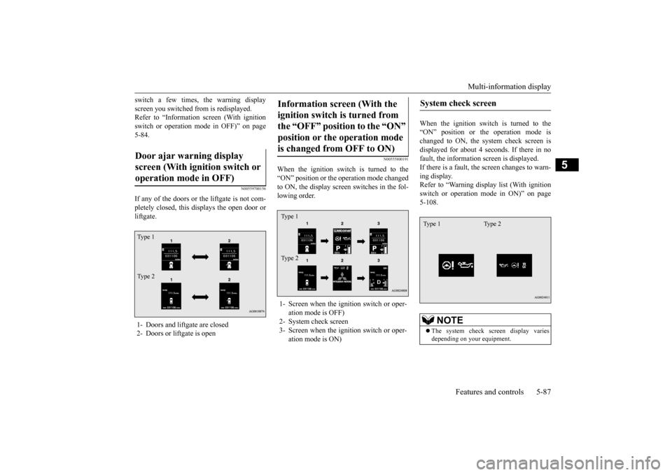
If any of the doors or the liftgate is not com- pletely closed, this displays the open door or liftgate.
N00555800191
When the ignition switch is turned to the“ON” position or the operation mode changed to ON, the display screen switches in the fol- lowing order.
When the ignition switch is turned to the “ON” position or the operation mode ischanged to ON, the system check screen is displayed for about 4 seconds. If there in no fault, the information screen is displayed.If there is a fault, the
screen changes to warn-
ing display. Refer to “Warning display list (With ignitionswitch or operation mode in ON)” on page5-108.
Door ajar warning display screen (With ignition switch or operation mode in OFF) 1- Doors and liftgate are closed 2- Doors or liftgate is openTy p e 1 Ty p e 2
Information screen (With the ignition switch is turned from the “OFF” position to the “ON” position or the operation mode is changed from OFF to ON) 1- Screen when the ignition switch or oper-
ation mode is OFF)
2- System check screen3- Screen when the ignition switch or oper-
ation mode is ON)Ty p e 1 Ty p e 2
System check screen
NOTE
The system check screen display varies depending on your equipment.
Type 1 Type 2
BK0202700US.bo
ok 87 ページ 2013年3月28日 木曜日 午前11時54分