MITSUBISHI SHOGUN 2003 Owner's Manual (in English)
Manufacturer: MITSUBISHI, Model Year: 2003, Model line: SHOGUN, Model: MITSUBISHI SHOGUN 2003Pages: 392, PDF Size: 14.34 MB
Page 301 of 392
On a flooded road(1) Avoid flooded roads. Water could enter
the brake discs, resulting in tempo-
rarily ineffective brakes. In such cases,
lightly depress the brake pedal to see
if the brakes operate properly. If they do
not, lightly depress the pedal several
times while driving in order to dry the
brake pads.
(2) When driving in rain or on a road with
many puddles a layer of water may
form between the tyres and the road
surface.
This reduces a tyre’s frictional resis-
tance on the road, resulting in loss of
steering stability and braking capabil-
ity.
To cope with this, observe the follow-
ing items:
(a)Drive your vehicle at a slow speed.
(b)Do not drive on worn tyres. Always
maintain the specified tyre inflation
pressures.
On a snow-covered or frozen road(1) When driving on a snow-covered or fro-
zen road, it is recommended that you
use snow tyres or tyre chains.
Refer to the“Snow tyres”and“Tyre
chains”sections.
(2) Avoid high-speed operation, sudden
acceleration, abrupt brake applica-
tion and sharp cornering.
(3) Depressing the brake pedal during
travel on such a road may cause tyre
slippage and skidding. When traction
between the tyres and the road is
reduced the wheels may skid and the
vehicle cannot readily be brought to a
stop by conventional braking tech-
niques. Braking will differ, depending
upon whether you have anti-lock
brakes (ABS). If you do have ABS,
brake by pressing the brake pedal
hard, and keeping it pressed. If you do
not have ABS, pump the brake pedal
with short rapid jabs, each time fully
applying and fully releasing for great-
est effect.
(4) Allow extra distance between your
vehicle and the vehicle in front of you,
and avoid sudden braking.
Tools and jack
EN01BOI
The storage location of the tools and jack
should be remembered in case of an emer-
gency.
For emergencies
8-3
Div:
Out put date:
Page 302 of 392
N01A138B
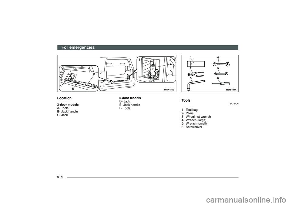
Location3-door models
A- Tools
B- Jack handle
C- Jack5-door models
D- Jack
E- Jack handle
F- Tools
N21B134A
Tools
EN21BOH
1- Tool bag
2- Pliers
3- Wheel nut wrench
4- Wrench (large)
5- Wrench (small)
6- Screwdriver
For emergencies
8-4Div:
Out put date:
Page 303 of 392
N21C135A
Jack and jack handle
EN21DOI
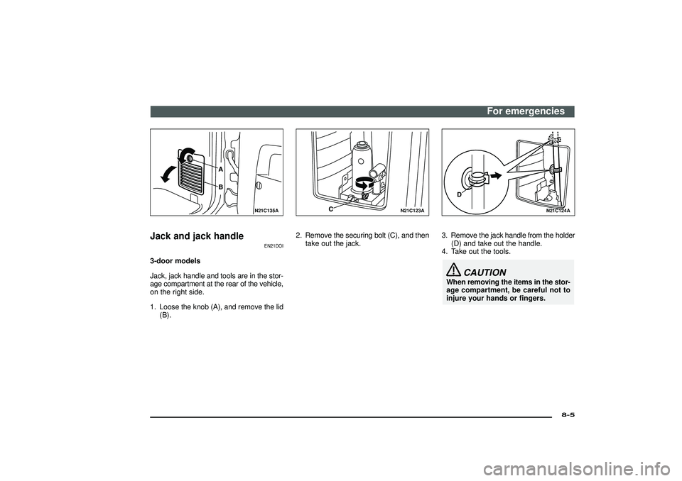
3-door models
Jack, jack handle and tools are in the stor-
age compartment at the rear of the vehicle,
on the right side.
1. Loose the knob (A), and remove the lid
(B).
N21C123A
2. Remove the securing bolt (C), and then
take out the jack.
N21C124A
3. Remove the jack handle from the holder
(D) and take out the handle.
4. Take out the tools.
CAUTION
When removing the items in the stor-
age compartment, be careful not to
injure your hands or fingers.
For emergencies
8-5
Div:
Out put date:
Page 304 of 392
N21C115A
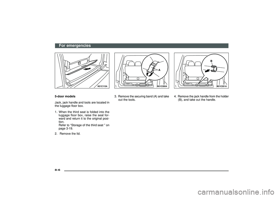
5-door models
Jack, jack handle and tools are located in
the luggage floor box.
1. When the third seat is folded into the
luggage floor box, raise the seat for-
ward and return it to the original posi-
tion.
Refer to“Storage of the third seat”on
page 3-19.
2. Remove the lid.
N21C200A
3. Remove the securing band (A) and take
out the tools.
N21C201A
4. Remove the jack handle from the holder
(B), and take out the handle.
For emergencies
8-6Div:
Out put date:
Page 305 of 392
N21C202A
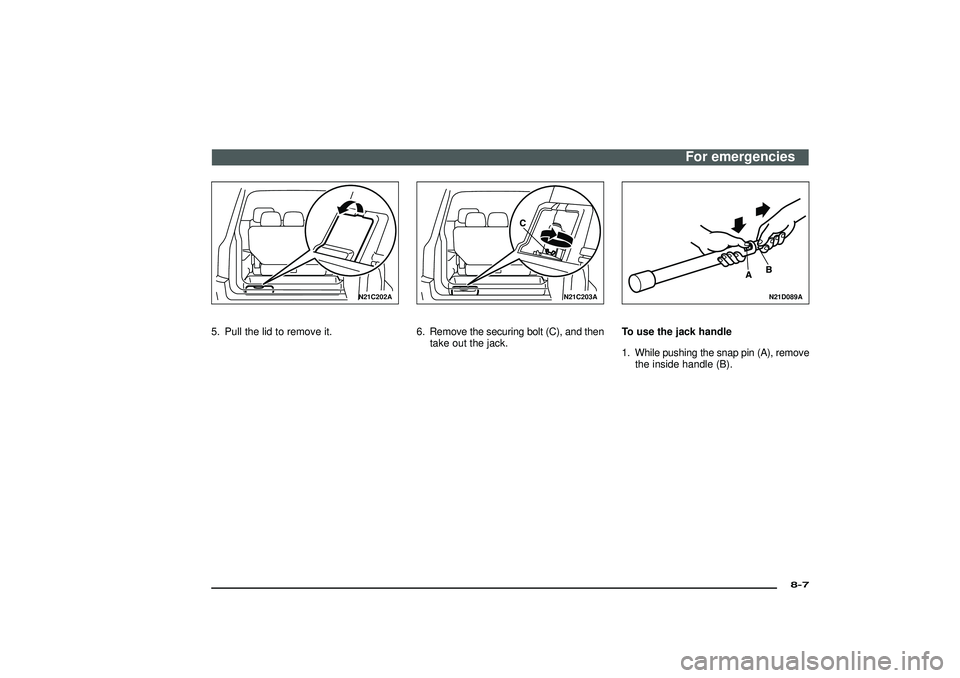
5. Pull the lid to remove it.
N21C203A
6. Remove the securing bolt (C), and then
take out the jack.
N21D089A
To use the jack handle
1. While pushing the snap pin (A), remove
the inside handle (B).
For emergencies
8-7
Div:
Out put date:
Page 306 of 392
N21D090A
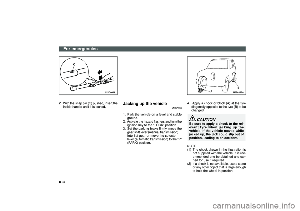
2. With the snap pin (C) pushed, insert theinside handle until it is locked.
Jacking up the vehicle
EN22AXSc
1. Park the vehicle on a level and stableground.
2. Activate the hazard flashers and turn the ignition key to the “LOCK” position.
3 . Se tth e parkin gbrak efirml y, mov ethe
gea rshif tleve r(manua ltransmission )
into 1st gear or move the selector
leve r(automati ctransmission )to the “P ”
(PARK) position.
N22A172A
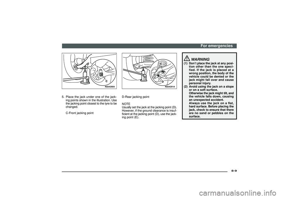
4. Apply a chock or block (A) at the tyre diagonally opposite to the tyre (B) to be
changed.
CAUTION
Be sure to apply a chock to the rel-
evant tyre when jacking up the
vehicle. If the vehicle moved while
jacked up, the jack could slip out of
position, leading to an accident.
NOTE
(1) The chock shown in the illustration is not supplied with the vehicle. It is rec-
ommended one be obtained and car-
ried for use if required.
(2) If a chock is not available, use a stone or any other object that is large enough
to hold the wheel in position.
For emergencies
8-8Div:
Out put date:
Page 307 of 392
N22A200A
5. Place the jack under one of the jack-
ing points shown in the illustration. Use
the jacking point closest to the tyre to be
changed.
C-Front jacking point
N22A201A
D-Rear jacking point
NOTE
Usually set the jack at the jacking point (D).
However, if the ground clearance is insuf-
ficient at the jacking point (D), use the jack-
ing point (E).
WARNING
(1) Don’t place the jack at any posi-
tion other than the one speci-
fied. If the jack is placed at a
wrong position, the body of the
vehicle could be dented or the
jack might fall over and cause
personal injury.
(2) Avoid using the jack on a slope
or on a soft surface.
Otherwise the jack might tilt, and
the vehicle falls down, causing
an unexpected accident.
Always use the jack on a flat,
hard surface. Before placing the
jack, check to ensure that there
are no sand or pebbles on the
surface.
For emergencies
8-9
Div:
Out put date:
Page 308 of 392
N22A205A
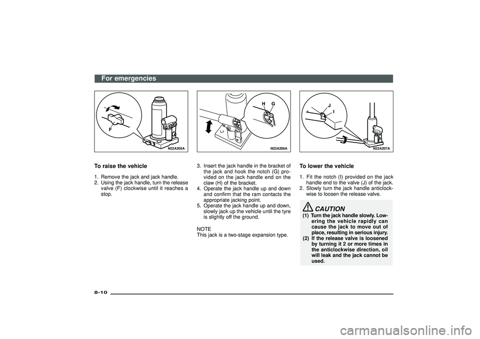
To raise the vehicle1. Remove the jack and jack handle.
2. Using the jack handle, turn the release
valve (F) clockwise until it reaches a
stop.
N22A206A
3. Insert the jack handle in the bracket of
the jack and hook the notch (G) pro-
vided on the jack handle end on the
claw (H) of the bracket.
4. Operate the jack handle up and down
and confirm that the ram contacts the
appropriate jacking point.
5. Operate the jack handle up and down,
slowly jack up the vehicle until the tyre
is slightly off the ground.
NOTE
This jack is a two-stage expansion type.
N22A207A
To lower the vehicle1. Fit the notch (I) provided on the jack
handle end to the valve (J) of the jack.
2. Slowly turn the jack handle anticlock-
wise to loosen the release valve.
CAUTION
(1) Turn the jack handle slowly. Low-
ering the vehicle rapidly can
cause the jack to move out of
place, resulting in serious injury.
(2) If the release valve is loosened
by turning it 2 or more times in
the anticlockwise direction, oil
will leak and the jack cannot be
used.
For emergencies
8-10Div:
Out put date:
Page 309 of 392
NOTE
Take care when lowering the vehicle, as
sudden closure of the jack release valve
can cause damage to the jack.
3. Remove the jack.
NOTE
(1) Occasionally, when the vehicle is
raised, the grooved portion of the ram
will not disengage. When this hap-
pens, rock the vehicle to lower the ram.
(2) When the jack is difficult to remove by
hand, insert the jack handle into the
holder and hook the jack handle notch
onto the holder notch and secure it
there. Then pull the jack handle and
remove the jack.
4. Press the piston down all the way, and
turn the release valve clockwise as far
as possible.
5. Store the jack and jack handle.
WARNING
(1) Raise the vehicle so the tyre just
clears the ground. It is danger-
ous to raise the vehicle any
higher.
(2) Never get under the vehicle while
using the jack. Avoid jarring the
raised vehicle or leaving it sup-
ported on the jack for any longer
than required. Both are very
dangerous.
(3) Do not start or run the engine
while the vehicle is on the jack.
The vehicle might start moving
causing the vehicle to fall down
from the jack.
(4) Do not turn the jacked up
wheels. The tyres remaining on
the ground may turn, causing
the vehicle body to fall down
from the jack.
(5) No one should stay in the vehicle
while the jack is used.
CAUTION
Use only the jack included with the
vehicle, and use it only for chang-
ing wheels.
N03A358A
Spare wheel
EN23A-N
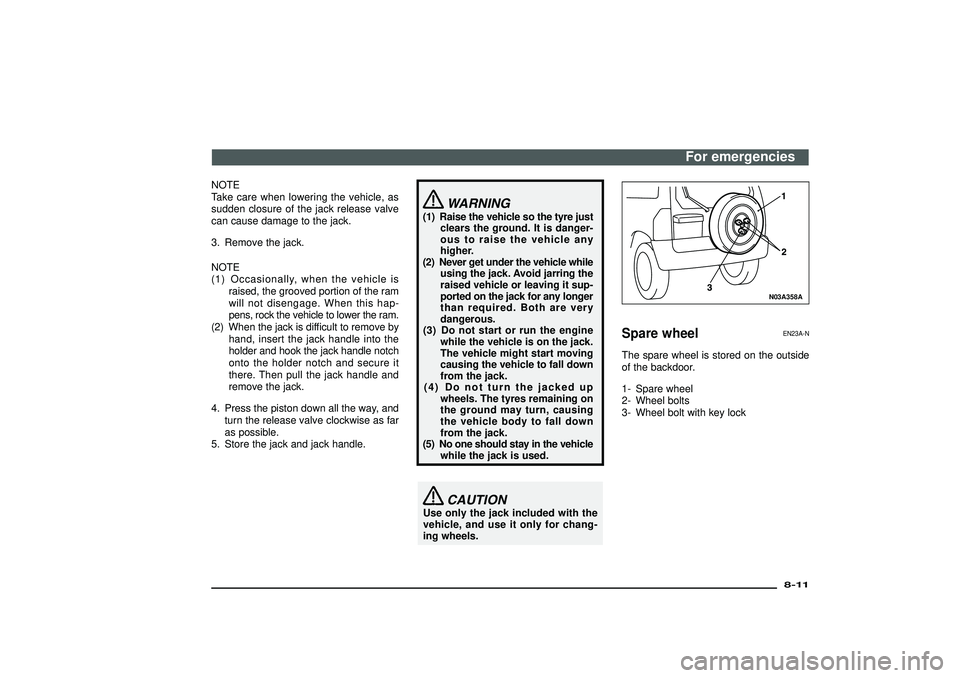
The spare wheel is stored on the outside
of the backdoor.
1- Spare wheel
2- Wheel bolts
3- Wheel bolt with key lock
For emergencies
8-11
Div:
Out put date:
Page 310 of 392
CAUTION
(1) Grasp the spare wheel firmly
when removing or attaching it.
(2) When removing the spare wheel,
put on gloves. Removing the
spare wheel with your hands
may cause injury to the fin-
gers.
(3) Check the air pressure of the
spare wheel frequently and
make sure it is ready for emer-
gency use at any time.
Driving with an insufficient tyre
pressure can lead to an acci-
dent. If you have no choice but
to drive with an insufficient tyre
pressure, keep your speed down
and inflate the tyre to the cor-
rect pressure as soon as pos-
sible. (Refer to“Tyre inflation
pressure”on page 9-14.)
Maintaining the spare wheel at
the highest specified air pres-
sure will ensure that it can
always be used under any con-
ditions (city/high-speed driv-
ing, varying load weight, etc.)
N03A082A
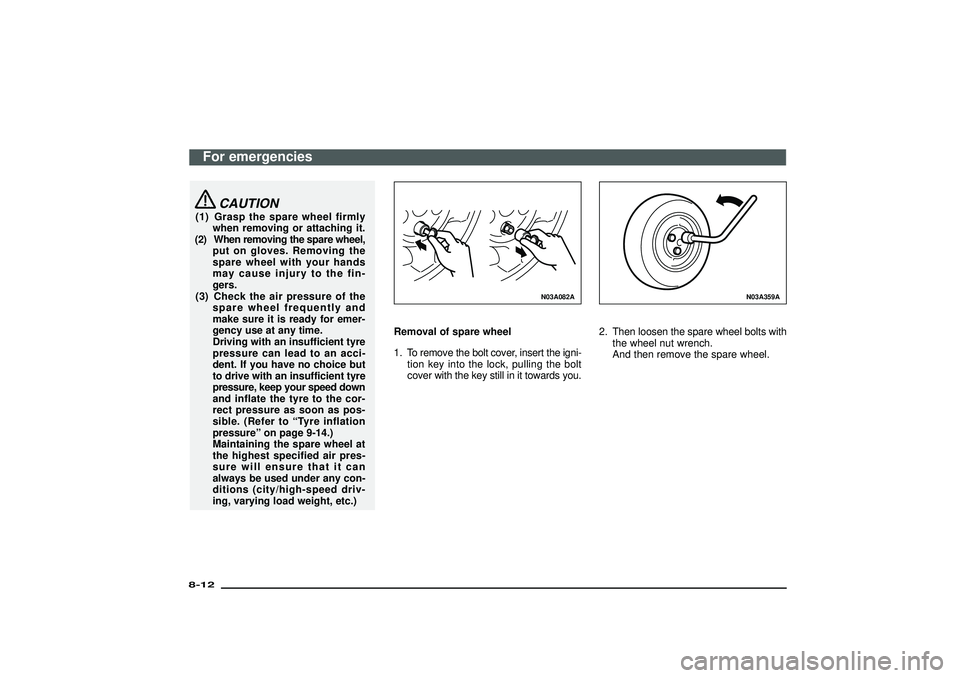
Removal of spare wheel
1. To remove the bolt cover, insert the igni-
tion key into the lock, pulling the bolt
cover with the key still in it towards you.
N03A359A
2. Then loosen the spare wheel bolts with
the wheel nut wrench.
And then remove the spare wheel.
For emergencies
8-12Div:
Out put date: