MITSUBISHI SPYDER 1990 Service Repair Manual
SPYDER 1990
MITSUBISHI
MITSUBISHI
https://www.carmanualsonline.info/img/19/57345/w960_57345-0.png
MITSUBISHI SPYDER 1990 Service Repair Manual
Trending: jump cable, open hood, service reset, wheel bolts, fuel, brake fluid, child seat
Page 1971 of 2103
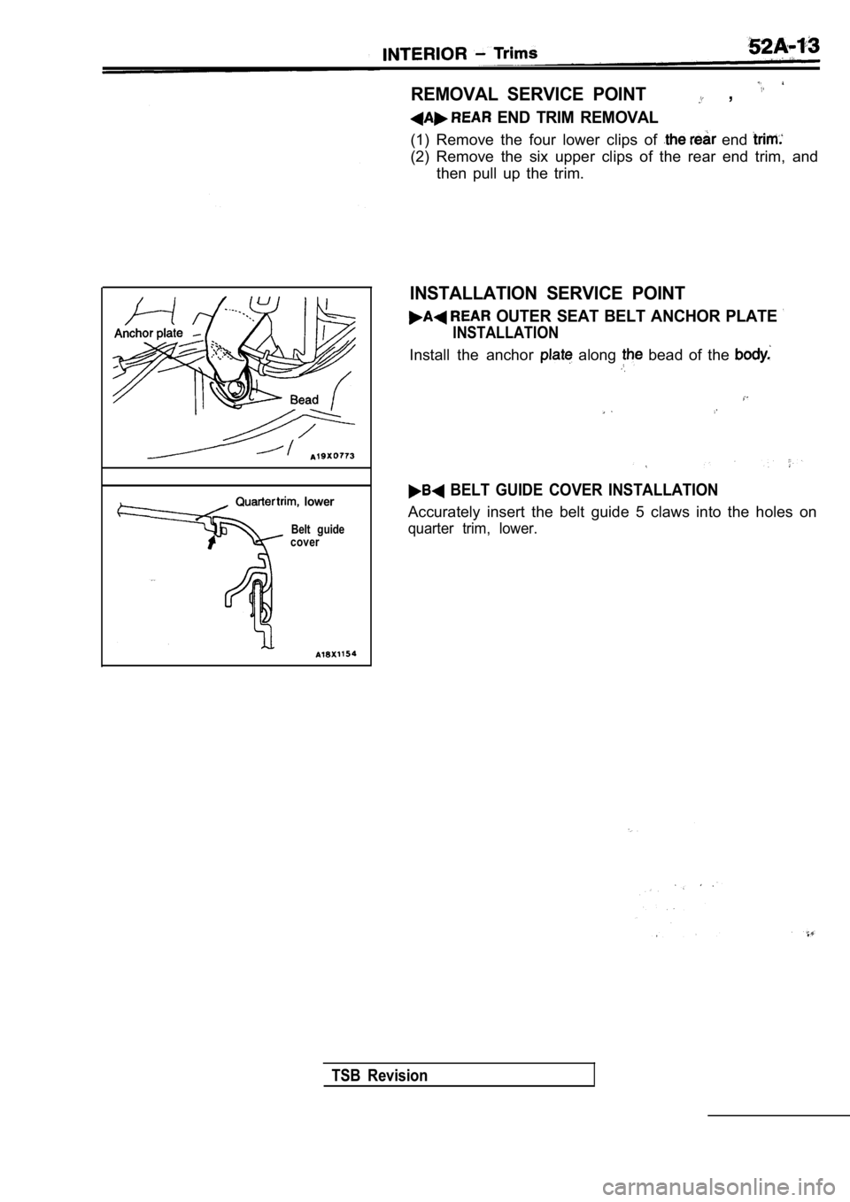
lower
Belt guide
cover
REMOVAL SERVICE POINT ,
END TRIM REMOVAL
(1) Remove the four lower clips of end
(2) Remove the six upper clips of the rear end trim , and
then pull up the trim.
INSTALLATION SERVICE POINT
OUTER SEAT BELT ANCHOR PLATE
INSTALLATION
Install the anchor along bead of the
BELT GUIDE COVER INSTALLATION
Accurately insert the belt guide 5 claws into the h oles on
quarter trim, lower.
TSB Revision
Page 1972 of 2103
HEADLINING
INTERIOR Headlining
SPECIAL TOOL
ToolTool number and name
General service toolApplication
Removal of trims, etc.
HEADLINING
REMOVAL AND INSTALLATION
52100140178
and Post-installation Operationl Front Pillar Trim and Quarter Trim Upper Removaland Installation (Refer to
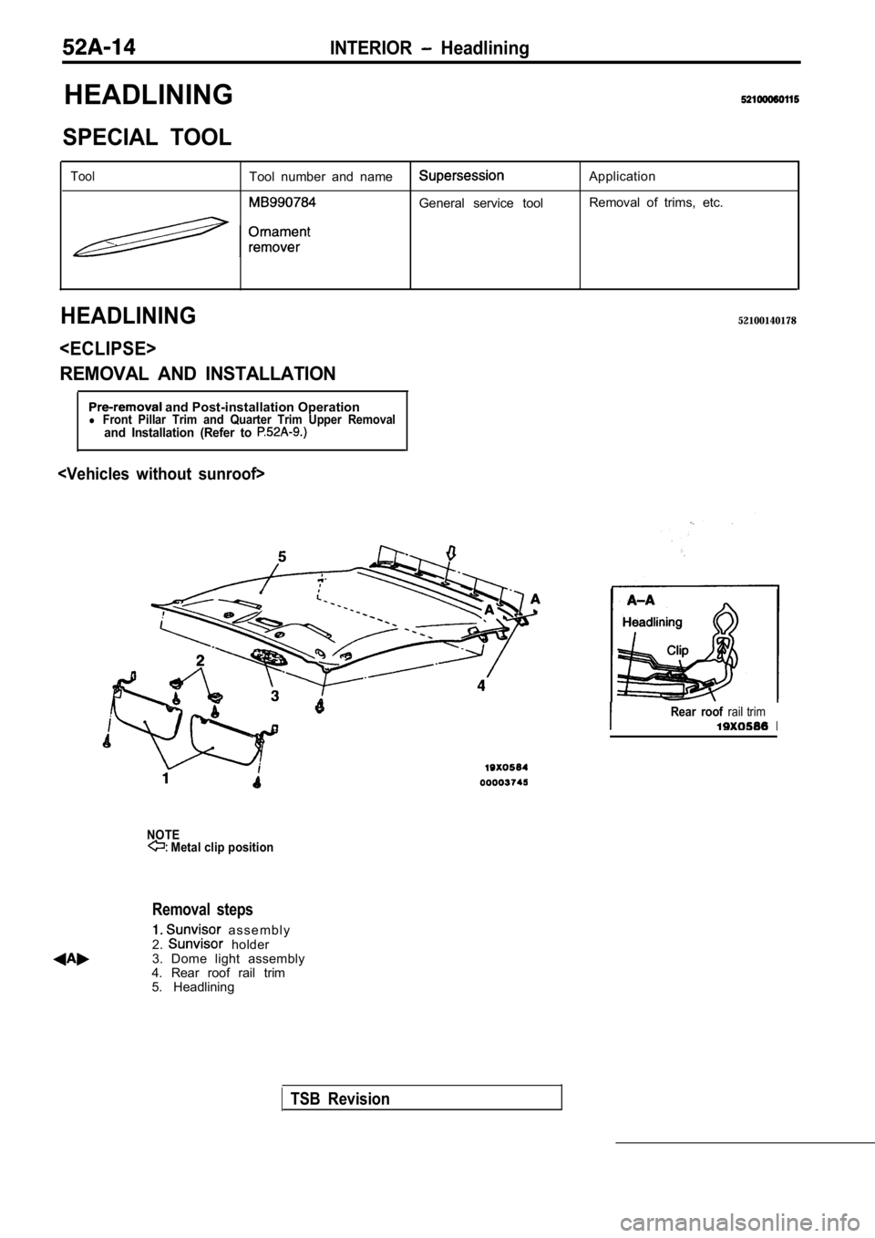
NOTE Metal clip position
Removal steps
a s s e m b l y
2. holder
3. Dome light assembly
4. Rear roof rail trim
5. Headlining
TSB Revision
Rear roof rail trimI
Page 1973 of 2103
INTERIOR Headlining
,
00003744
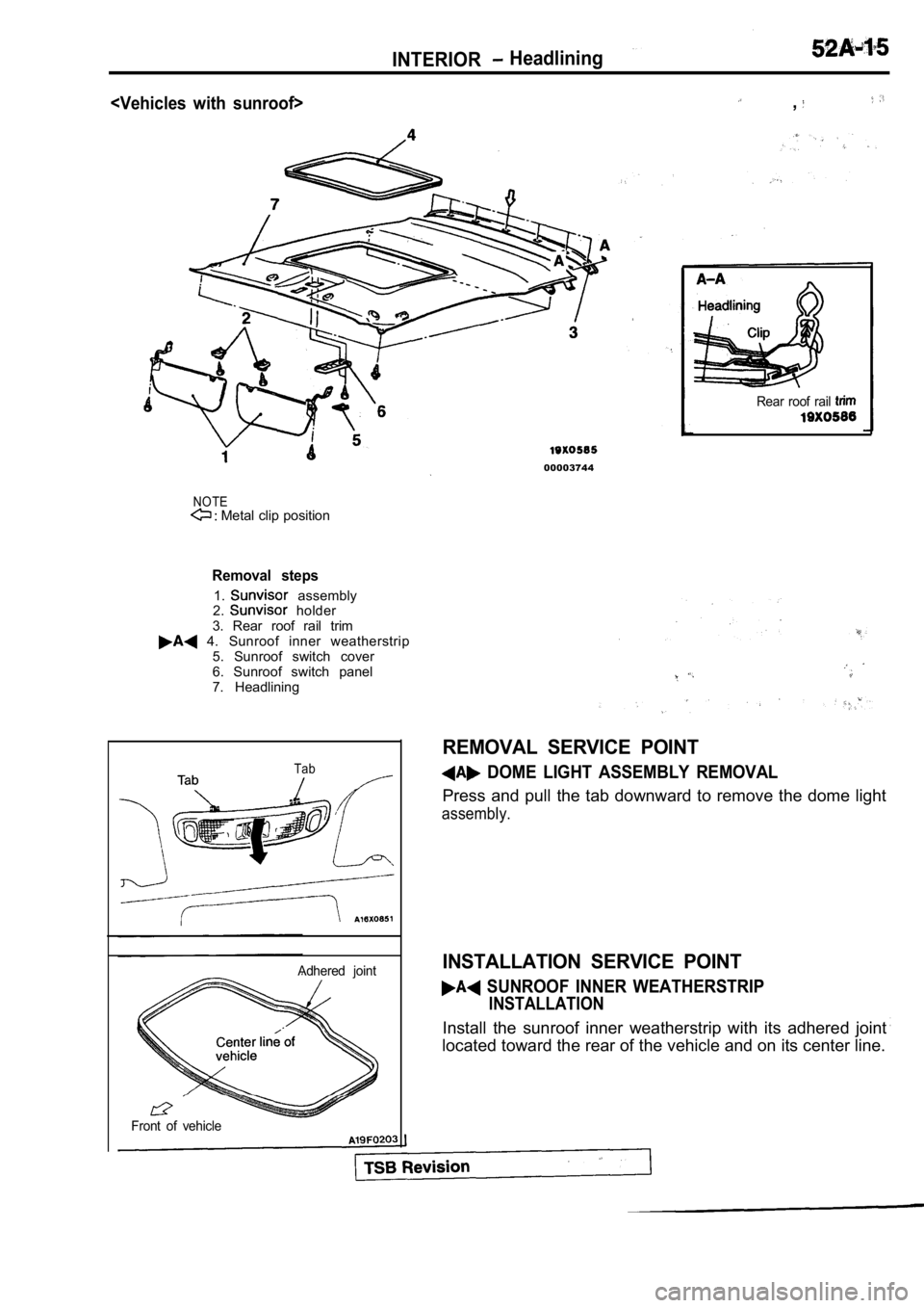
NOTE Metal clip position
Rear roof rail
Removal steps
1. assembly
2. holder
3. Rear roof rail trim
4. Sunroof inner weatherstrip 5. Sunroof switch cover
6. Sunroof switch panel
7. Headlining
Tab
REMOVAL SERVICE POINT
DOME LIGHT ASSEMBLY REMOVAL
Press and pull the tab downward to remove the dome light
assembly.
INSTALLATION SERVICE POINT
SUNROOF INNER WEATHERSTRIP
INSTALLATION
Install the sunroof inner weatherstrip with its adhered joint
located toward the rear of the vehicle and on its c enter line.
Adhered joint
Front of vehicle
Page 1974 of 2103
INTERIOR Inside Rear View Mirror
INSIDE REAR VIEW MIRROR
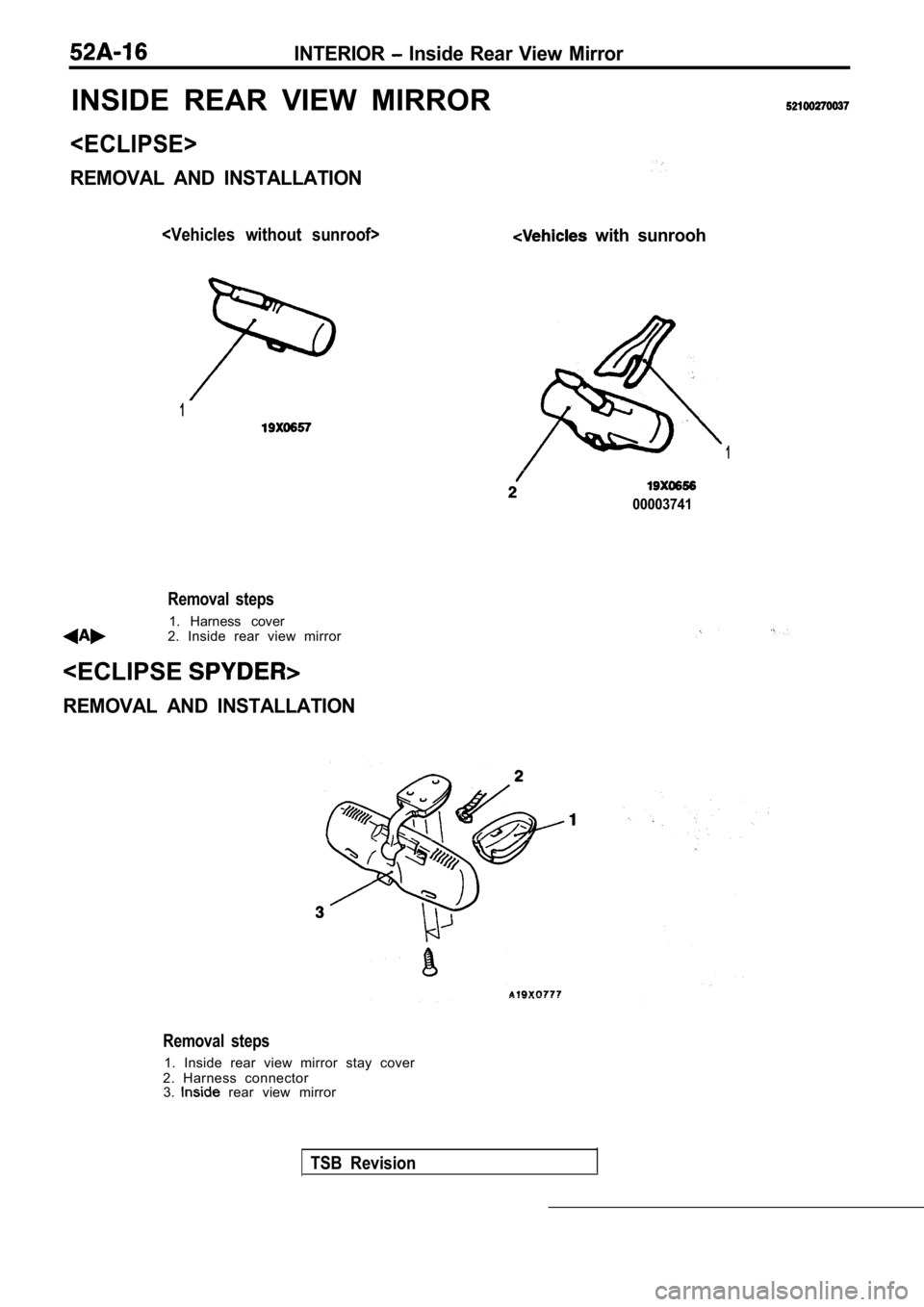
REMOVAL AND INSTALLATION
with sunrooh
1
1
00003741
Removal steps
1. Harness cover
2. Inside rear view mirror
REMOVAL AND INSTALLATION
Removal steps
1. Inside rear view mirror stay cover
2. Harness connector 3.
rear view mirror
TSB Revision
Page 1975 of 2103
INTERIORInside Rear View Mirror 7
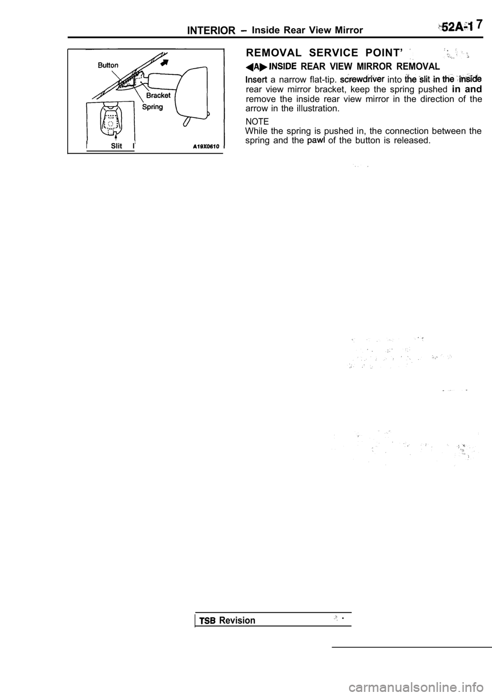
ISlit IREMOVAL SERVICE POINT’
REAR VIEW MIRROR REMOVAL
a narrow flat-tip. into
rear view mirror bracket, keep the spring pushed
in and
remove the inside rear view mirror in the direction of the
arrow in the illustration.
NOTE
While the spring is pushed in, the connection betwe en the
spring and the
of the button is released.
Revision .
Page 1976 of 2103
INTERIOR Front Seat
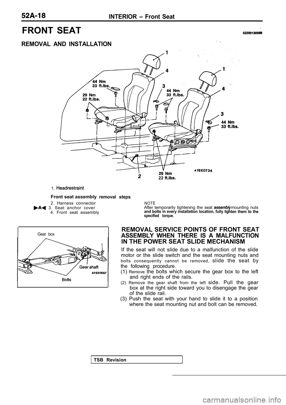
FRONT SEAT
REMOVAL AND INSTALLATION
1.
Front seat assembly
2. Harness connector
3. Seat anchor cover 4. Front seat assembly
22
removal steps
Gear box
TSB Revision
N O T EAfter temporarily tightening the seat mounting nutsand bolts in every installation location, fully ten them to thespecified torque.
REMOVAL SERVICE POINTS OF FRONT SEAT
ASSEMBLY WHEN THERE IS A MALFUNCTION
IN THE POWER SEAT SLIDE MECHANISM
If the seat will not slide due to a malfunction of the slide
motor or the slide switch and the seat mounting nut s and
b o l t s c o n s e q u e n t l y c a n n o t b e r e m o v e d , slide the seat by
the following procedure.
(1)Remove the bolts which secure the gear box to the left
and right ends of the rails.
(2) Remove the gear shaft from the left side. Pull the gear
box at the right side toward you to disengage the g ear
of the slide rail.
(3) Push the seat with your hand to slide it to a p osition
where the seat mounting nut and bolt can be removed .
Page 1977 of 2103
Section A-A
III
INTERIOR Front Seat
INSTALLATION SERVICE POINT
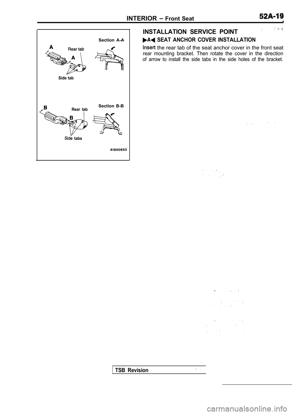
SEAT ANCHOR COVER INSTALLATION
the rear tab of the seat anchor cover in the front seat
rear mounting bracket. Then rotate the cover in the direction
of arrow to install the side tabs in the side holes of the bracket.
Side tab
Rear tab
Section B-B
tabs
TSB Revision
Page 1978 of 2103
INTERIOR Front Seat
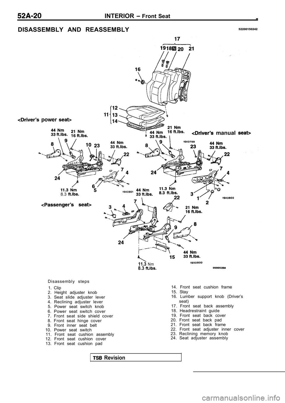
DISASSEMBLY AND REASSEMBLY52200150242
power
manual
8.3
11.3Nm8.3
D i s a s s e m b l y s t e p s1. Clip
2. Height adjuster knob
3. Seat slide adjuster lever
4. Reclining adjuster lever 5. Power seat switch knob
6. Power seat switch cover
7. Front seat side shield cover
8. Front seat hinge cover
9. Front inner seat belt
10. Power seat switch 11. Front seat cushion assembly
12. Front seat cushion cover
13. Front seat cushion pad 14. Front seat cushion frame
15. Stay
16. Lumber support knob (Driver’s
seat)
17. Front seat back assembly
18. Headrestraint guide
19. Front seat back cover
20. Front seat back pad
21. Front seat back frame
22. Front seat adjuster inner cover
23. Reclining memory knob 24. Seat adjuster assembly
Revision
Page 1979 of 2103
INTERIOR Seat
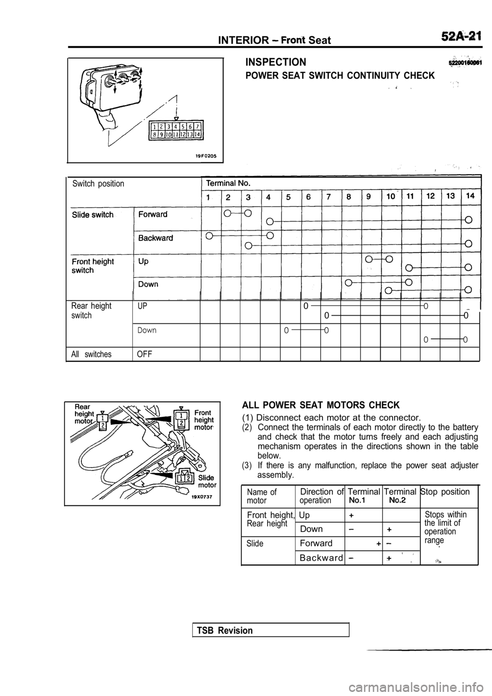
INSPECTION
POWER SEAT SWITCH CONTINUITY CHECK
Switch position
Rear height
UP0 0
switch0 0
Down0 0
0 0
All switchesOFF
ALL POWER SEAT MOTORS CHECK
(1) Disconnect each motor at the connector.
(2)Connect the terminals of each motor directly to the battery
and check that the motor turns freely and each adju sting
mechanism operates in the directions shown in the t able
below.
(3)If there is any malfunction, replace the power seat adjuster
assembly.
Name ofDirection of Terminal Terminal Stop position
motor operation
Front height, UpStops within
Rear height the limit of
Downoperation
Slide
Forwardrange.
B a c k w a r d
TSB Revision
Page 1980 of 2103
INTERIOR Rear Seat
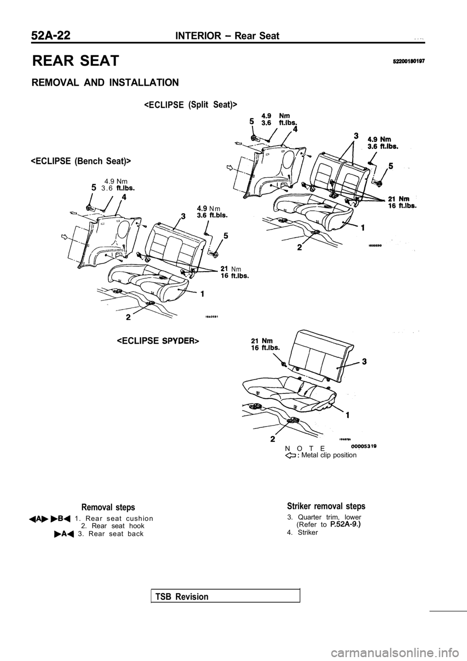
REAR SEAT
REMOVAL AND INSTALLATION
4.9 Nm
5 3 . 6
(Split Seat)>
4.9N m
Removal steps
1 . R e a r s e a t c u s h i o n
2. Rear seat hook
3. Rear seat back
N m
N O T E Metal clip position
Striker removal steps
3. Quarter trim, lower(Refer to
4. Striker
TSB Revision
Trending: air bleeding, overheating, oil capacities, sunroof, tire pressure reset, compression ratio, seat memory
