MITSUBISHI SPYDER 1990 Service Repair Manual
SPYDER 1990
MITSUBISHI
MITSUBISHI
https://www.carmanualsonline.info/img/19/57345/w960_57345-0.png
MITSUBISHI SPYDER 1990 Service Repair Manual
Trending: warning lights, refrigerant type, coolant level, torque, brake light, trailer, fuse
Page 1951 of 2103
EXTERIOR Rear Wiper and
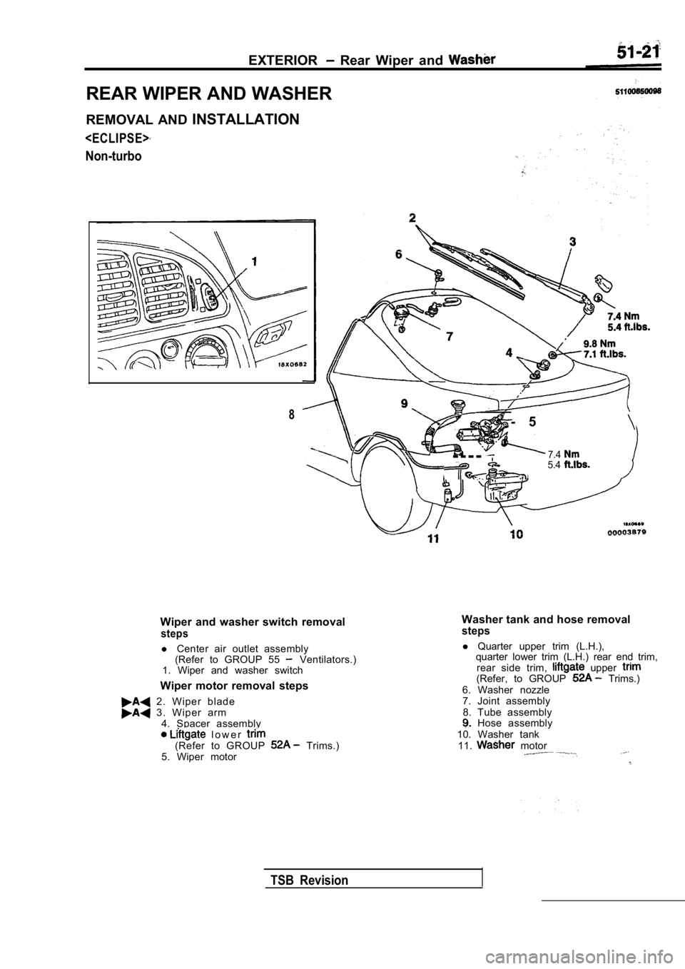
REAR WIPER AND WASHER
REMOVAL AND INSTALLATION
Non-turbo
Wiper and washer switch removal
steps
l Center air outlet assembly
(Refer to GROUP 55 Ventilators.)
1. Wiper and washer switch
Wiper motor removal steps
2. Wiper blade 3 . W i p e r a r m 4. Spacer assembly
l o w e r (Refer to GROUP Trims.)
5. Wiper motor - 5
- - - -7.45.4
8
Washer tank and hose removalsteps
l
Quarter upper trim (L.H.),
quarter lower trim (L.H.) rear end trim,
rear side trim,
upper (Refer, to GROUP Trims.)
6. Washer nozzle 7. Joint assembly
8. Tube assembly
Hose assembly
10. Washer tank 11.
motor
TSB Revision
Page 1952 of 2103
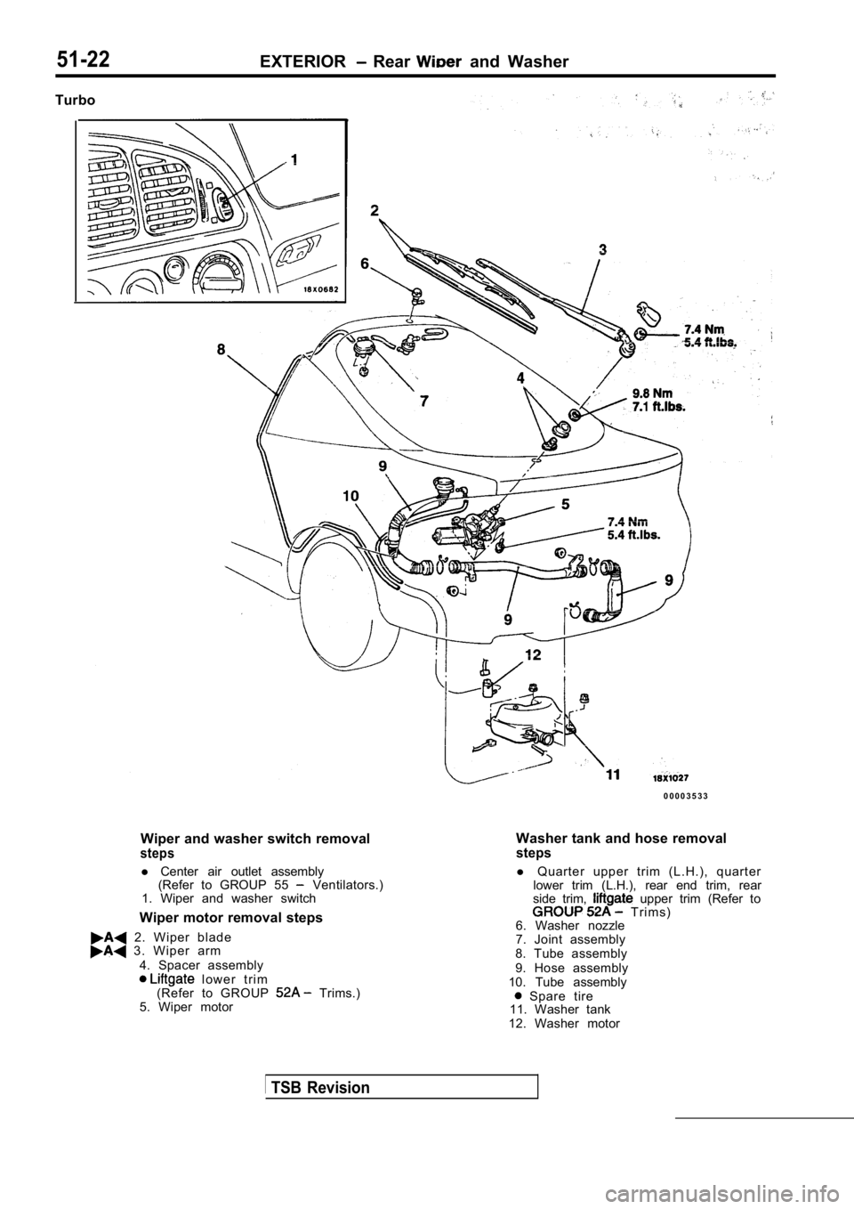
51-22EXTERIOR Rear and Washer
Turbo
0 0 0 0 3 5 3 3
Wiper and washer switch removal
steps
l Center air outlet assembly
(Refer to GROUP 55 Ventilators.)
1. Wiper and washer switch
Wiper motor removal steps
2. Wiper blade 3 . W i p e r a r m 4. Spacer assembly
l o w e r t r i m
(Refer to GROUP Trims.)
5. Wiper motor
TSB Revision
Washer tank and hose removal
steps
l Quarter upper trim (L.H.), quarter
lower trim (L.H.), rear end trim, rear
side trim,
upper trim (Refer to T r i m s )
6. Washer nozzle
7. Joint assembly
8. Tube assembly
9. Hose assembly
10. Tube assembly
Spare tire
11. Washer tank
12. Washer motor
Page 1953 of 2103
EXTERIOR Rear Wiper
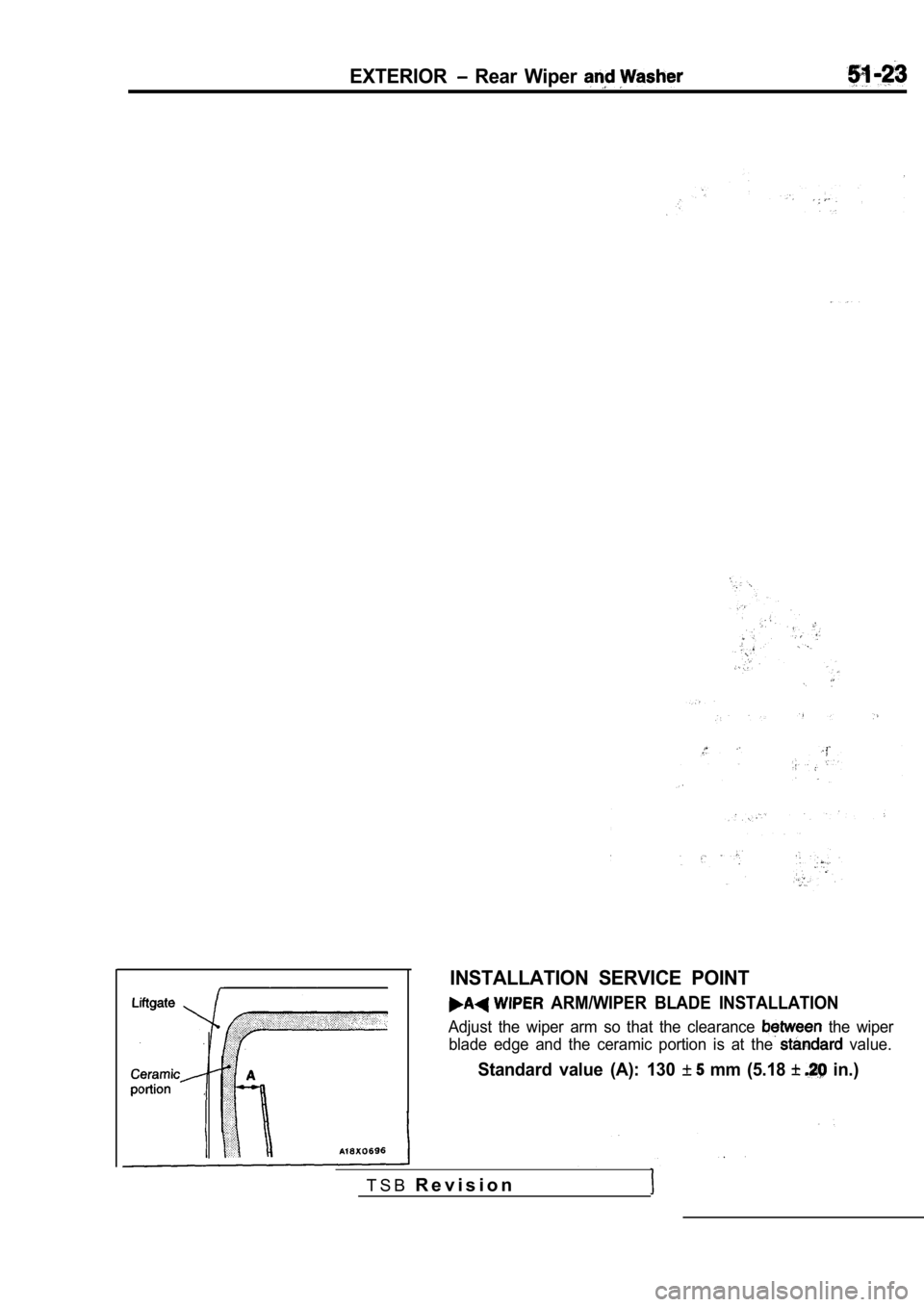
INSTALLATION SERVICE POINT
ARM/WIPER BLADE INSTALLATION
Adjust the wiper arm so that the clearance the wiper
blade edge and the ceramic portion is at the
value.
Standard value (A): 130 mm (5.18 in.)
T S B R e v i s i o n
Page 1954 of 2103
51-24EXTERIOR Rear Wiper and Washer
Inspection operating
Inspection stopped
0 0 0 0 3 6 3 4
INSPECTION51100950022
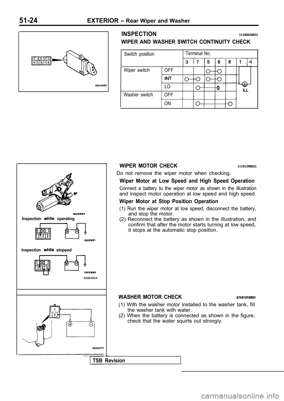
WIPER AND WASHER SWITCH CONTINUITY CHECK
Wiper switchOFF
Switch position Terminal No.
4
LO0
Washer switch
OFFIII
ONI
WIPER MOTOR CHECK51101290025
Do not remove the wiper motor when checking.
Wiper Motor at Low Speed and High Speed Operation
Connect a battery to the wiper motor as shown in th e illustration
and inspect motor operation at low speed and high speed.
Wiper Motor at Stop Position Operation
(1) Run the wiper motor at low speed, disconnect the battery,
and stop the motor.
(2) Reconnect the battery as shown in the illustrat ion, and
confirm that after the motor starts turning at low speed,
it stops at the automatic stop position.
WASHER MOTOR CHECK
(1) With the washer motor installed to the washer t ank, fill
the washer tank with water.
(2) When the battery is connected as shown in the f igure,
check that the water squirts out strongly.
TSB Revision
Page 1955 of 2103
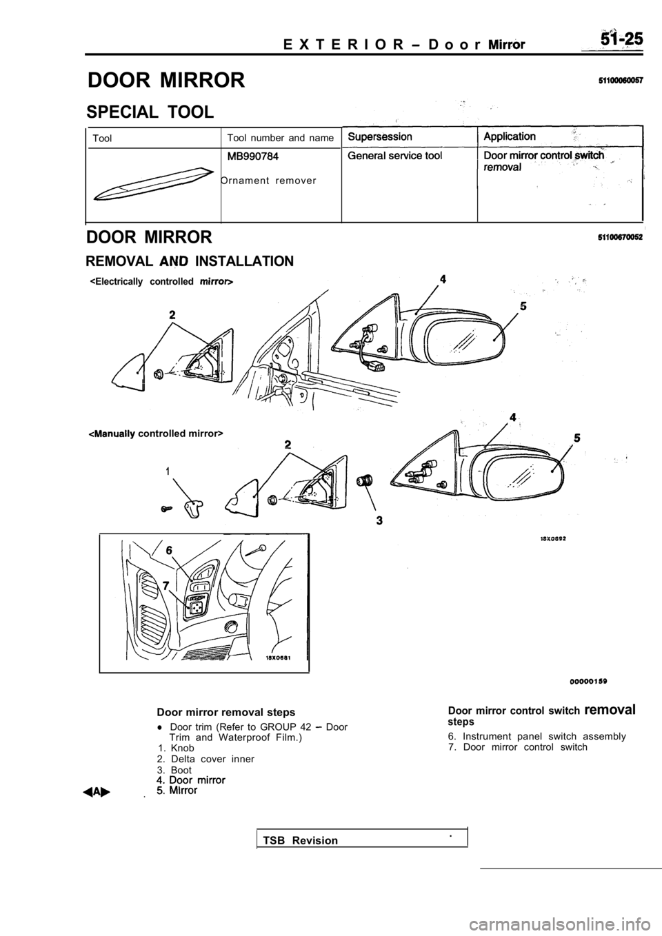
E X T E R I O R D o o r
DOOR MIRROR
SPECIAL TOOL
ToolTool number and name
O r n a m e n t r e m o v e r
DOOR MIRROR
REMOVAL INSTALLATION
controlled mirror>
1
Door mirror removal steps
lDoor trim (Refer to GROUP 42 Door
Trim and Waterproof Film.)
1. Knob
2. Delta cover inner
3. Boot
.
Door mirror control switch removalsteps
6. Instrument panel switch assembly 7. Door mirror control switch
TSB Revision .
Page 1956 of 2103
51-26EXTERIOR Door Mirror
section
1 2 3
4 5 6 7
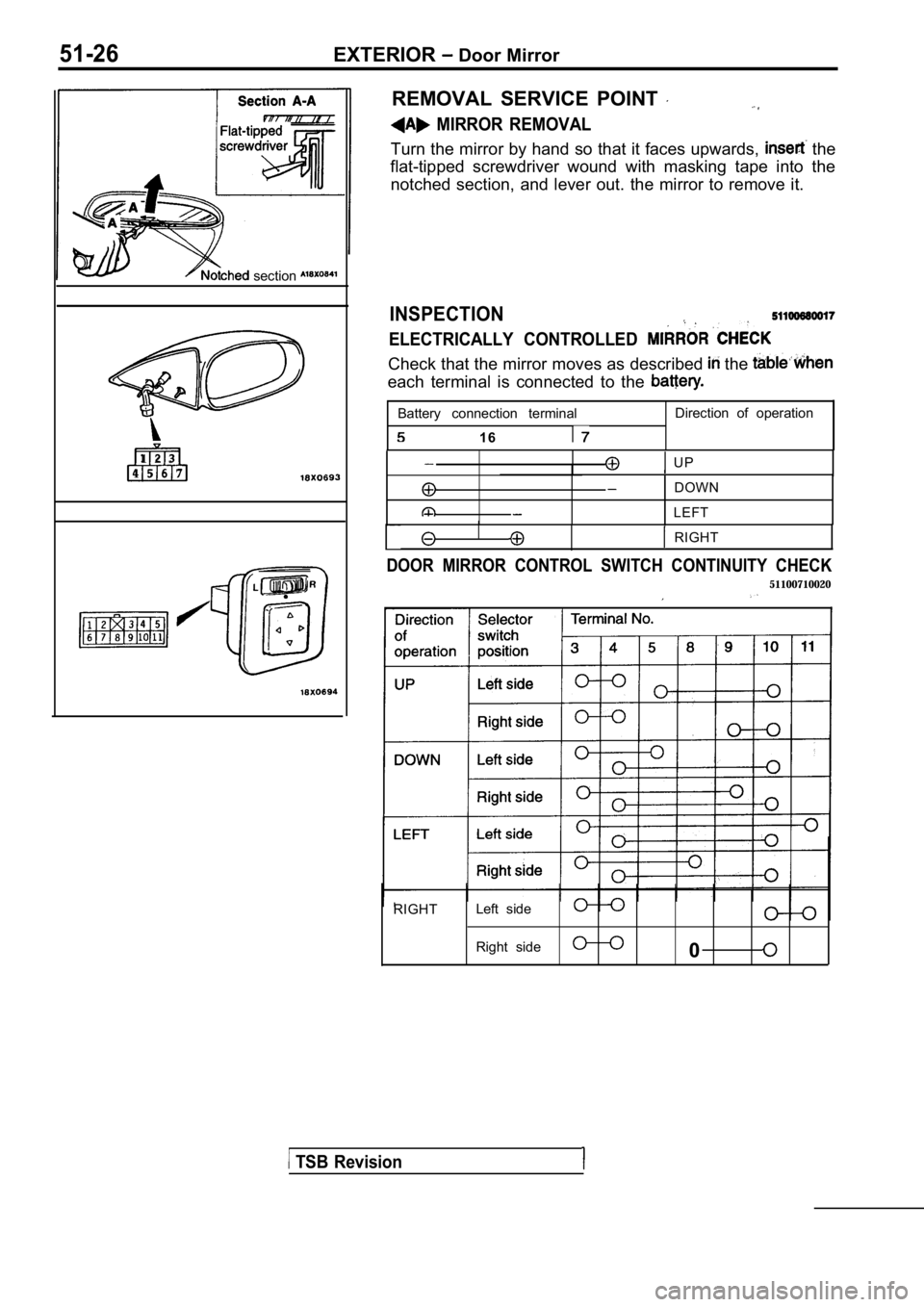
REMOVAL SERVICE POINT
MIRROR REMOVAL
Turn the mirror by hand so that it faces upwards, the
flat-tipped screwdriver wound with masking tape int o the
notched section, and lever out. the mirror to remov e it.
INSPECTION
ELECTRICALLY CONTROLLED
Check that the mirror moves as described the
each terminal is connected to the
Battery connection terminal
1 6
Direction of operation
I UP
DOWN
LEFT
I RIGHT
DOOR MIRROR CONTROL SWITCH CONTINUITY CHECK
51100710020
RIGHTLeft side
Right side
0
TSB Revision
Page 1957 of 2103
INTERIOR AND
SUPPLEMENTAL
RESTRAINT SYSTEM
CONTENTS
INTERIOR. . . . . . . . . . . . . . . . . . . . . . . . . . . . . . . . . . . . . . . . . . . . . . . . . . . .
SUPPLEMENTAL RESTRAINT SYSTEM (SRS) . . . . . . . . . . . . . . . . . . .
Page 1958 of 2103
Page 1959 of 2103
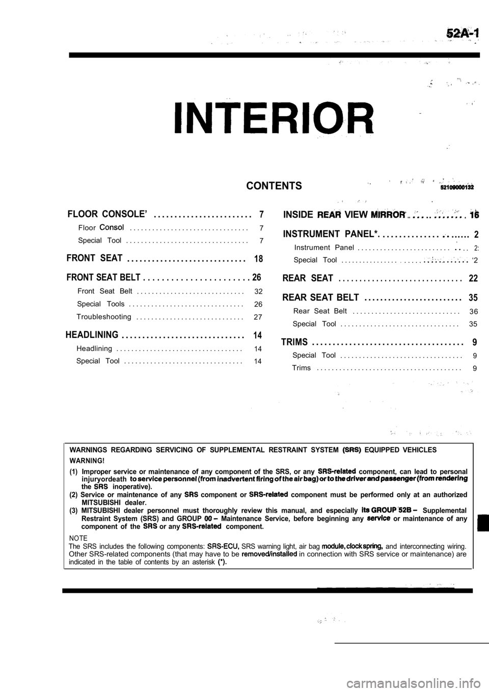
CONTENTS
FLOOR CONSOLE’. . . . . . . . . . . . . . . . . . . . . . . .7INSIDE VIEW .....
Floor. . . . . . . . . . . . . . . . . . . . . . . . . . . . . . . .7INSTRUMENT PANEL*.. . . . . . . . . . . . . .......2Special Tool . . . . . . . . . . . . . . . . . . . . . . . . . . . . . . . . . 7
Instrument Panel . . . . . . . . . . . . . . . . . . . . . . . . .. .2:
FRONT SEAT. . . . . . . . . . . . . . . . . . . . . . . . . . . . .18Special Tool. . . . . . . . . . . . . . . ... . . . .. ‘2
FRONT SEAT BELT . . . . . . . . . . . . . . . . . . . . . . . 26REAR SEAT. . . . . . . . . . . . . . . . . . . . . . . . . . . . . .22
Front Seat Belt
. . . . . . . . . . . . . . . . . . . . . . . . . . . . . 32REAR SEAT BELT. . . . . . . . . . . . . . . . . . . . . . . . .35Special Tools . . . . . . . . . . . . . . . . . . . . . . . . . . . . . . .
26
3 6
Troubleshooting Rear Seat Belt
. . . . . . . . . . . . . . . . . . . . . . . . . . . . .
. . . . . . . . . . . . . . . . . . . . . . . . . . . . . 27
Special Tool . . . . . . . . . . . . . . . . . . . . . . . . . . . . . . . . 35
HEADLINING. . . . . . . . . . . . . . . . . . . . . . . . . . . . . .14TRIMS. . . . . . . . . . . . . . . . . . . . . . . . . . . . . . . . . . . . .9Headlining . . . . . . . . . . . . . . . . . . . . . . . . . . . . . . . . . .14Special Tool. . . . . . . . . . . . . . . . . . . . . . . . . . . . . . . . .9Special Tool . . . . . . . . . . . . . . . . . . . . . . . . . . . . . . . .14Trims. . . . . . . . . . . . . . . . . . . . . . . . . . . . . . . . . . . . . . .
9
WARNINGS REGARDING SERVICING OF SUPPLEMENTAL RESTRA INT SYSTEM EQUIPPED VEHICLES
WARNING!
(1)
Improper service or maintenance of any component of the SRS, or any component, can lead to personal
injuryordeath
the inoperative).
(2) Service or maintenance of any component or component must be performed only at an authorized
MITSUBISHI dealer.
(3) MITSUBISHI dealer personnel must thoroughly rev iew this manual, and especially
Supplemental
Restraint System (SRS) and GROUP Maintenance Service, before beginning any or maintenance of any
component of the or any component.
NOTEThe SRS includes the following components: SRS warning light, air bag and interconnecting wiring.Other SRS-related components (that may have to be in connection with SRS service or maintenance) areindicated in the table of contents by an asterisk
Page 1960 of 2103
INTERIOR Instrument Panel
INSTRUMENT PANEL
.
52100050055
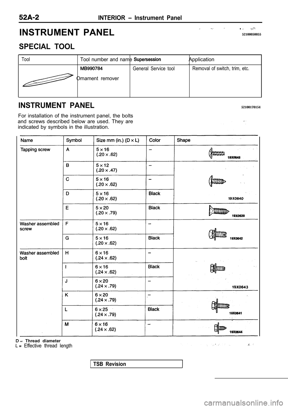
SPECIAL TOOL
ToolTool number and name
General Service tool
Ornament remover
Application
Removal of switch, trim, etc.
INSTRUMENT PANEL52100170154
For installation of the instrument panel, the bolts
and screws described below are used. They are indicated by symbols in the illustration.
Thread diameter
Effective thread length
TSB Revision
Trending: tow, torque, seats, washer fluid, tire pressure, warning lights, maintenance schedule
