MITSUBISHI SPYDER 1990 Service Repair Manual
Manufacturer: MITSUBISHI, Model Year: 1990, Model line: SPYDER, Model: MITSUBISHI SPYDER 1990Pages: 2103, PDF Size: 68.98 MB
Page 1941 of 2103
EXTERIOR Aero Parts
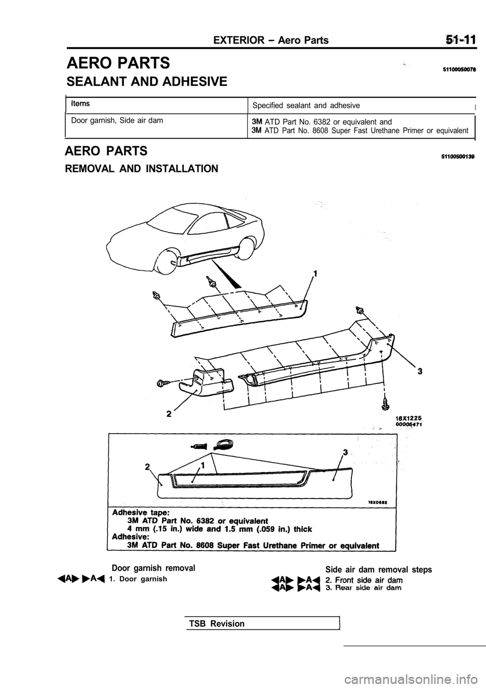
AERO PARTS
SEALANT AND ADHESIVE
Specified sealant and adhesiveI
Door garnish, Side air dam ATD Part No. 6382 or equivalent and
ATD Part No. 8608 Super Fast Urethane Primer or equivalent
AERO PARTS
REMOVAL AND INSTALLATION
Door garnish removal
1. Door garnish
Side air dam removal steps
TSB Revision
Page 1942 of 2103
EXTERIOR Aero Parts
0 0 0 0 5 4 7 2
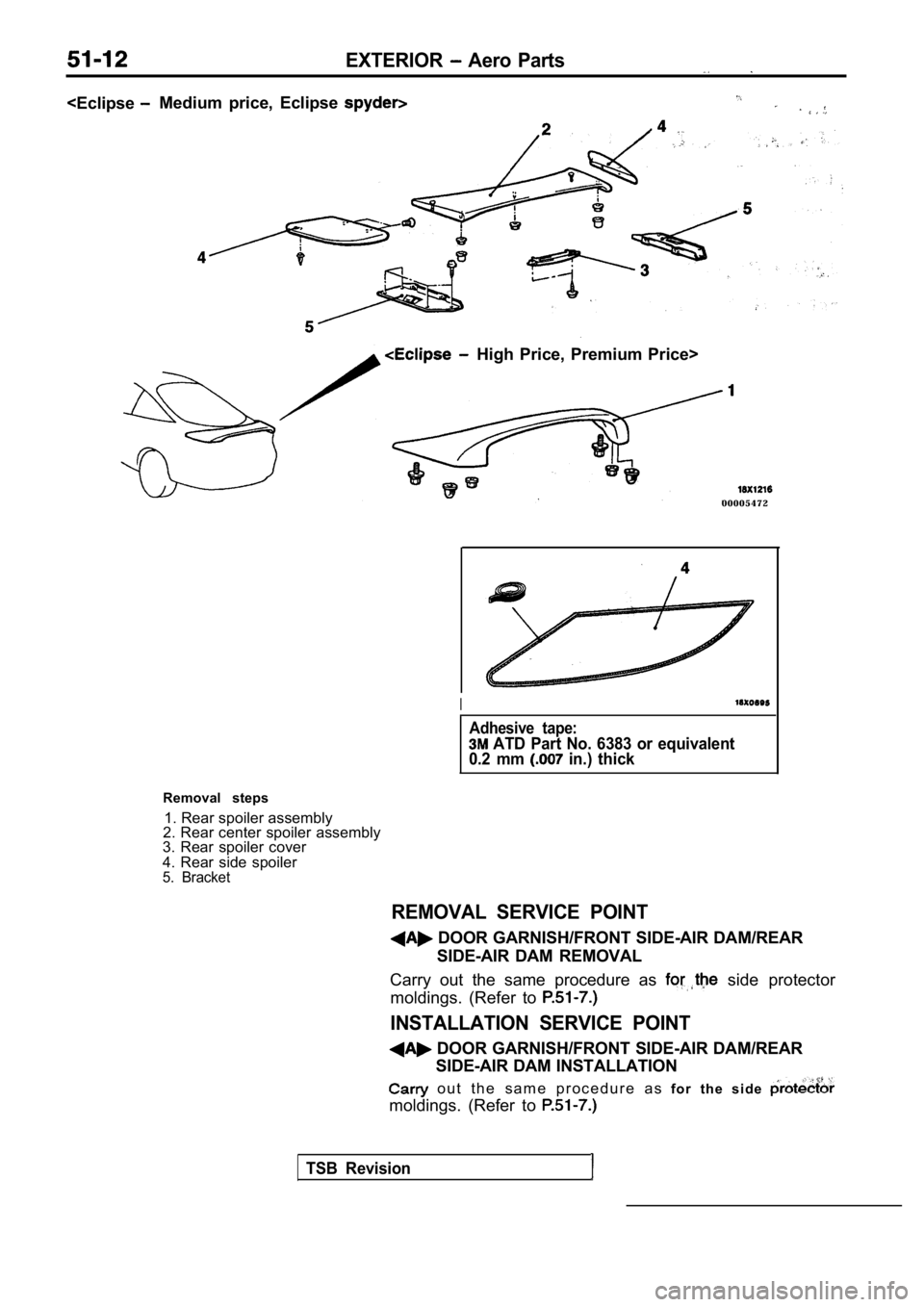
Removal steps 1. Rear spoiler assembly
2. Rear center spoiler assembly
3. Rear spoiler cover
4. Rear side spoiler
5. Bracket
REMOVAL SERVICE POINT
I
Adhesive tape:
ATD Part No. 6383 or equivalent
0.2 mm in.) thick
DOOR GARNISH/FRONT SIDE-AIR DAM/REAR
SIDE-AIR DAM REMOVAL
Carry out the same procedure as
side protector
moldings. (Refer to
INSTALLATION SERVICE POINT
DOOR GARNISH/FRONT SIDE-AIR DAM/REAR SIDE-AIR DAM INSTALLATION
o u t t h e s a m e p r o c e d u r e a s f o r t h e s i d e
moldings. (Refer to
TSB Revision
Page 1943 of 2103
EXTERIOR Wiper and .
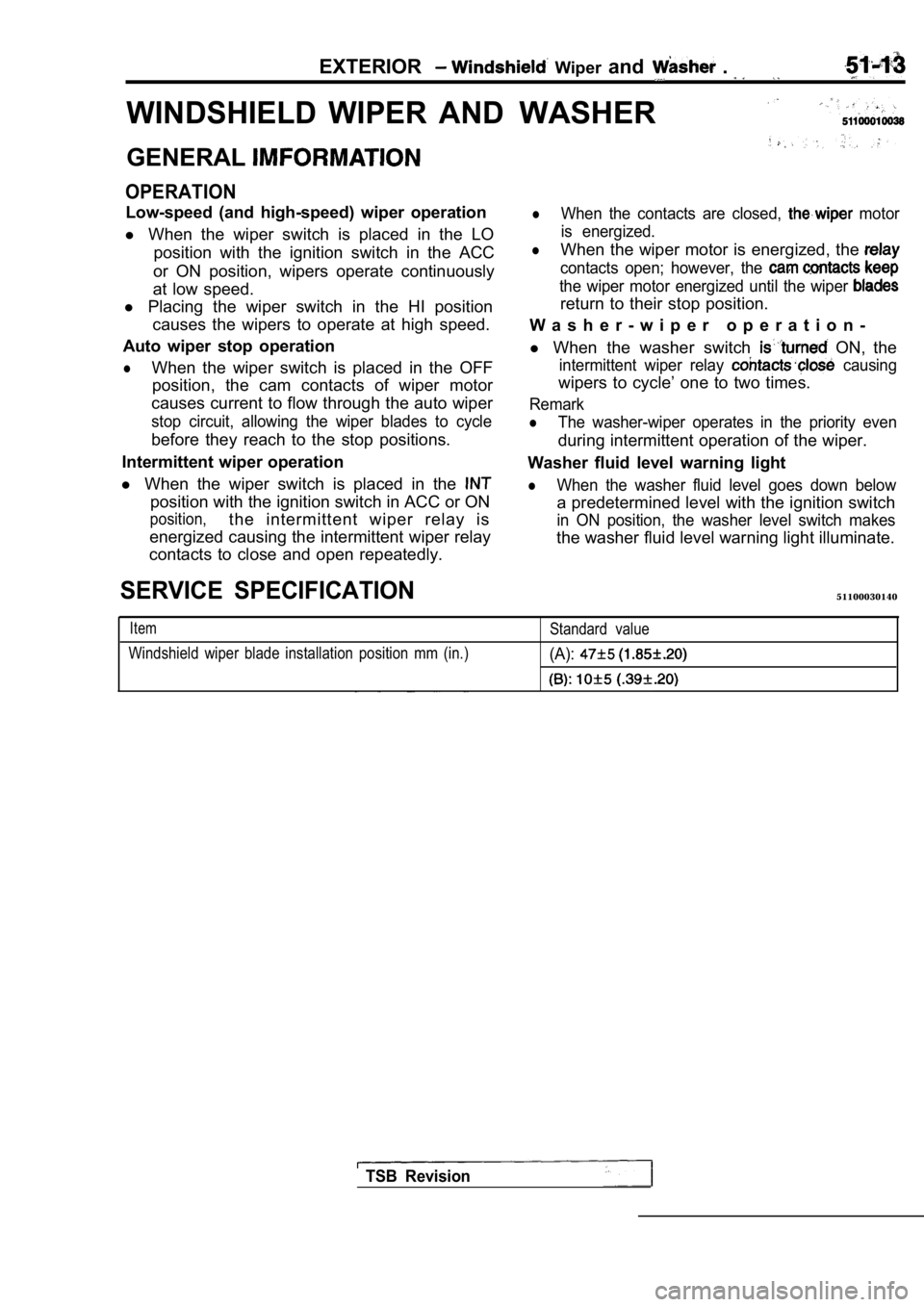
WINDSHIELD WIPER ANDWASHER
GENERAL
OPERATION
Low-speed (and high-speed) wiper operation
l When the wiper switch is placed in the LO
position with the ignition switch in the ACC
or ON position, wipers operate continuously
at low speed.
l Placing the wiper switch in the HI position
causes the wipers to operate at high speed.
Auto wiper stop operation
lWhen the wiper switch is placed in the OFF position, the cam contacts of wiper motor
causes current to flow through the auto wiper
stop circuit, allowing the wiper blades to cycle
before they reach to the stop positions.
Intermittent wiper operation
l When the wiper switch is placed in the
position with the ignition switch in ACC or ON
position,the intermittent wiper relay is
energized causing the intermittent wiper relay
contacts to close and open repeatedly.
lWhen the contacts are closed, motor
is energized.
lWhen the wiper motor is energized, the
contacts open; however, the
the wiper motor energized until the wiper
return to their stop position.
W a s h e r - w i p e r o p e r a t i o n -
l When the washer switch
ON, the
intermittent wiper relay causing
wipers to cycle’ one to two times.
Remark
lThe washer-wiper operates in the priority even
during intermittent operation of the wiper.
Washer fluid level warning light
lWhen the washer fluid level goes down below
a predetermined level with the ignition switch
in ON position, the washer level switch makes
the washer fluid level warning light illuminate.
SERVICE SPECIFICATION51100030140
Item
Windshield wiper blade installation position mm (in .)Standard value(A):
TSB Revision
Page 1944 of 2103
EXTERIOR Windshield and Washer
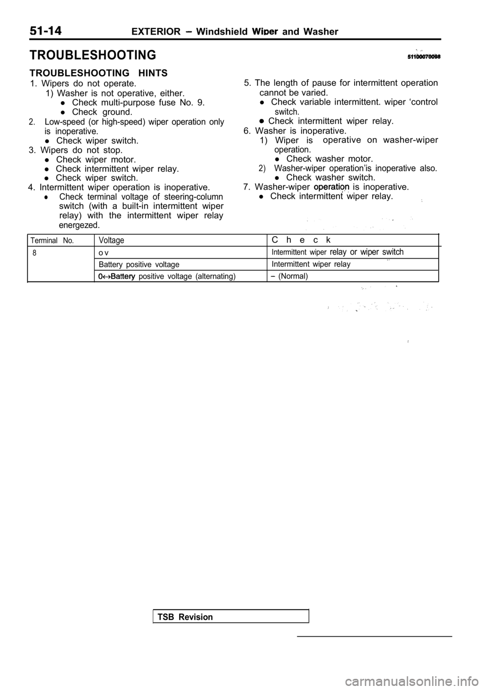
TROUBLESHOOTING
TROUBLESHOOTING HINTS1. Wipers do not operate. 1) Washer is not operative, either.l Check multi-purpose fuse No. 9.
l Check ground.
2.Low-speed (or high-speed) wiper operation only
is inoperative.
l Check wiper switch.
3. Wipers do not stop. l Check wiper motor.
l Check intermittent wiper relay.
l Check wiper switch.
4. Intermittent wiper operation is inoperative.
lCheck terminal voltage of steering-column
switch (with a built-in intermittent wiper relay) with the intermittent wiper relay
energezed.
5. The length of pause for intermittent operation
cannot be varied.
l Check variable intermittent. wiper ‘control
switch.
Check intermittent wiper relay.
6. Washer is inoperative. 1) Wiper is operative on washer-wiper
operation.
l
Check washer motor.
2)Washer-wiper operation’is inoperative also.
l Check washer switch.
7. Washer-wiper
is inoperative.
l Check intermittent wiper relay.
Terminal No.
8
Voltage
o v
Battery positive voltage
positive voltage (alternating)
C h e c k
Intermittent wiper relay or wiper switch
Intermittent wiper relay
(Normal)
TSB Revision
Page 1945 of 2103
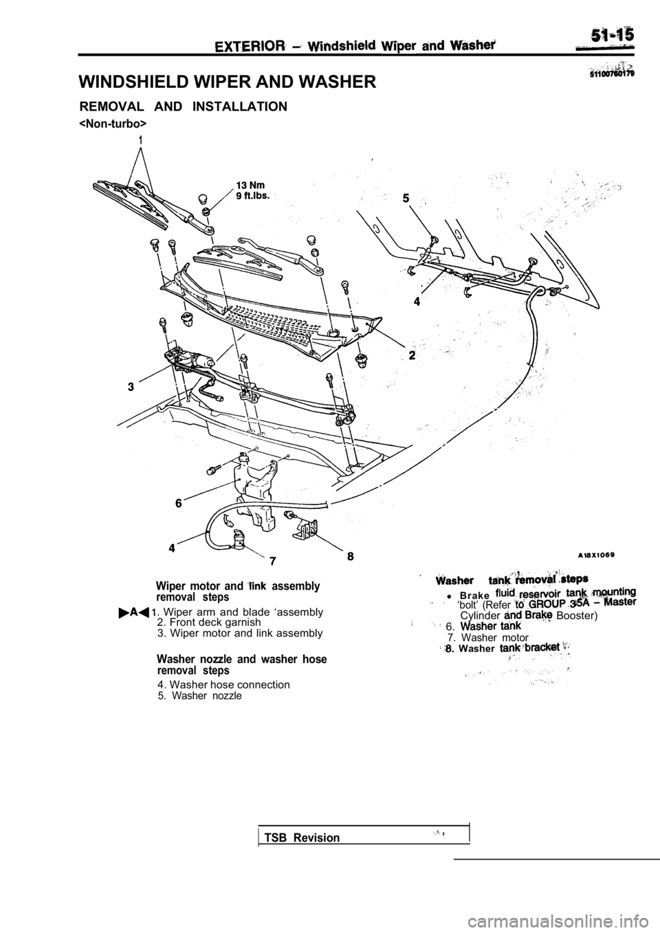
WINDSHIELD WIPER AND WASHERREMOVAL AND INSTALLATION
1
Wiper motor and assemblyremoval steps
Wiper arm and blade ‘assembly
2. Front deck garnish
3. Wiper motor and link assembly
l B r a k e.‘bolt’ (Refer Cylinder Booster)
6. 7. Washer motor Washer
Washer nozzle and washer hose
removal steps
4. Washer hose connection5. Washer nozzle
TSB Revision ,
Page 1946 of 2103
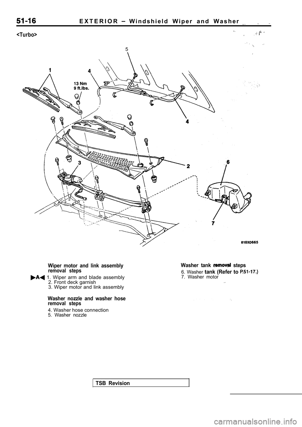
E X T E R I O R W i n d s h i e l d W i p e r a n d W a s h e r
,
5
Wiper motor and link assemblyremoval steps
1. Wiper arm and blade assembly2. Front deck garnish
3. Wiper motor and link assembly
Washer nozzle and washer hoseremoval steps
4. Washer hose connection5. Washer nozzle
TSB Revision
Washer tank steps
6. Washer tank (Refer to 7. Washer motor
Page 1947 of 2103
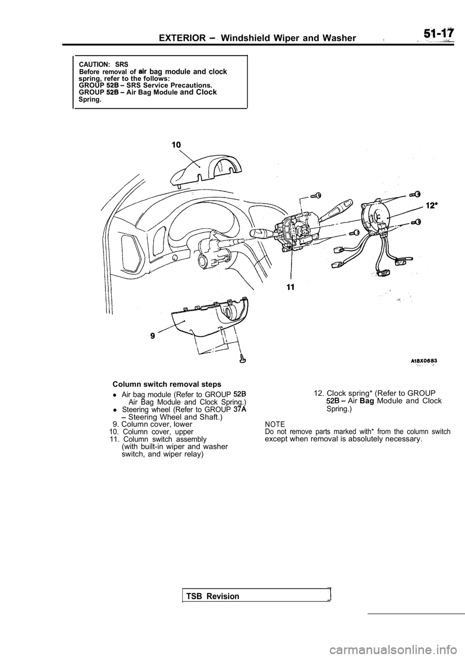
EXTERIOR Windshield Wiper and Washer,
CAUTION: SRSBefore removal of bag module and clockspring, refer to the follows:GROUP SRS Service Precautions.
GROUP Air Bag Module and ClockSpring.
Column switch removal steps
l Air bag module (Refer to GROUP Air Bag Module and Clock Spring.)l Steering wheel (Refer to GROUP Steering Wheel and Shaft.)
9. Column cover, lower
10. Column cover, upper
11. Column switch assembly
(with built-in wiper and washer
switch, and wiper relay)
12. Clock spring* (Refer to GROUP Air Bag Module and Clock
Spring.)
NOTE
Do not remove parts marked with* from the column sw itch
except when removal is absolutely necessary.
TSB Revision
Page 1948 of 2103
EXTERIOR Windshield Wiper and Washer
I
Inspection while operatingspeed speed
stop
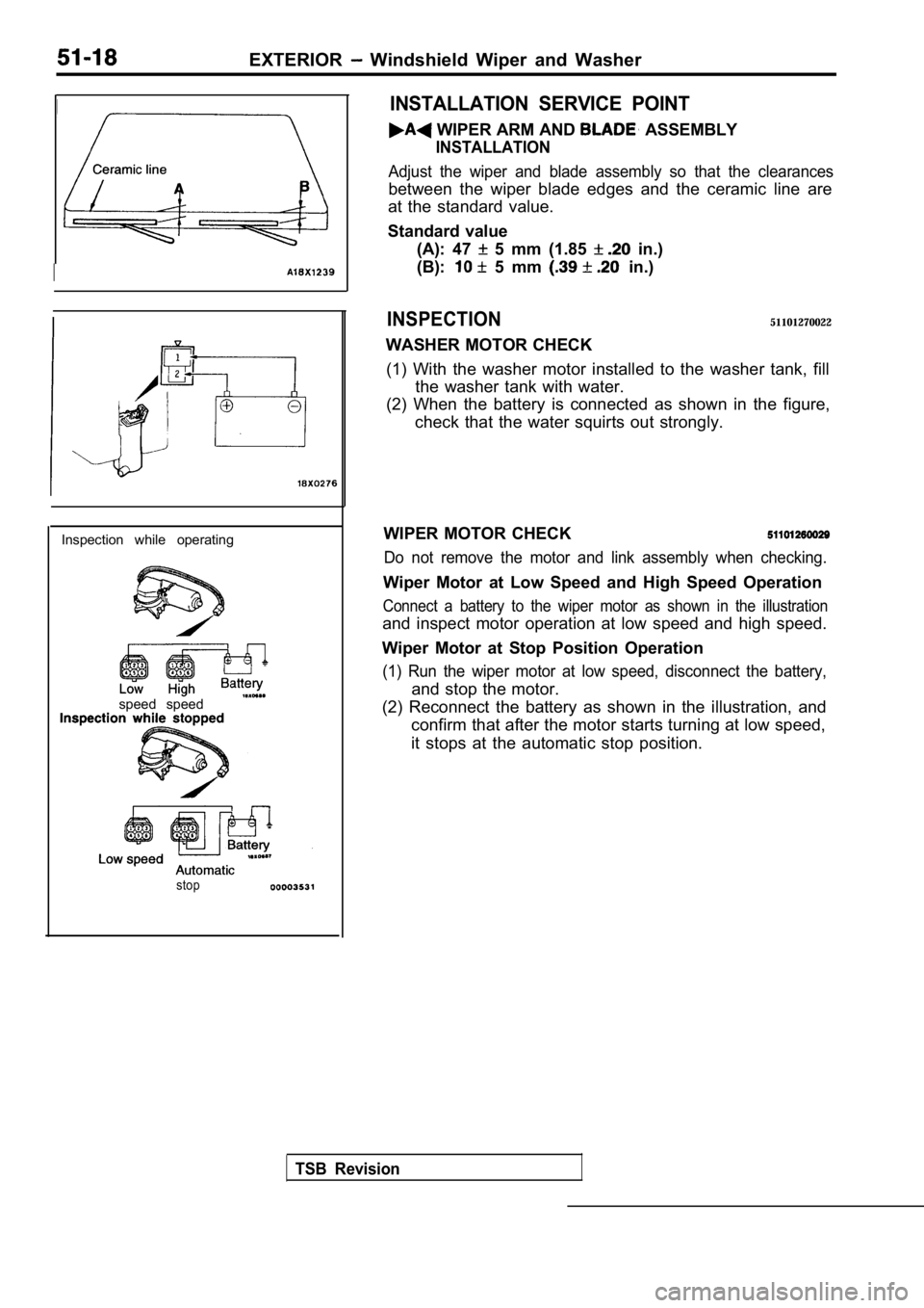
INSTALLATION SERVICE POINT
WIPER ARM AND ASSEMBLY
INSTALLATION
Adjust the wiper and blade assembly so that the cle arances
between the wiper blade edges and the ceramic line are
at the standard value.
Standard value (A): 47
5 mm (1.85 in.)
(B):
5 mm in.)
INSPECTION51101270022
WASHER MOTOR CHECK
(1) With the washer motor installed to the washer t ank, fill
the washer tank with water.
(2) When the battery is connected as shown in the f igure,
check that the water squirts out strongly.
WIPER MOTOR CHECK
Do not remove the motor and link assembly when chec king.
Wiper Motor at Low Speed and High Speed Operation
Connect a battery to the wiper motor as shown in the illustration
and inspect motor operation at low speed and high speed.
Wiper Motor at Stop Position Operation
(1) Run the wiper motor at low speed, disconnect th e battery,
and stop the motor.
(2) Reconnect the battery as shown in the illustrat ion, and
confirm that after the motor starts turning at low speed,
it stops at the automatic stop position.
TSB Revision
Page 1949 of 2103
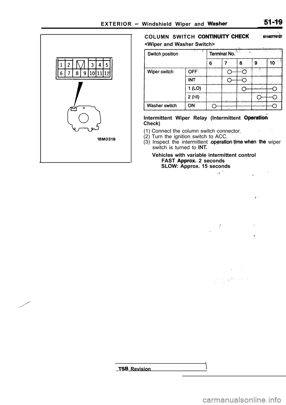
E X T E R I O R Windshield Wiper and
C O L U M N S W I T C H
Intermittent Wiper Relay (Intermittent
Check)
(1) Connect the column switch connector.
(2) Turn the ignition switch to ACC.
(3) Inspect the intermittent
wiper
switch is turned to
Vehicles with variable intermittent control
FAST
2 seconds
SLOW: Approx. 15 seconds
,
,
,
Revision
Page 1950 of 2103
EXTERIOR Rear Wiper and Washer
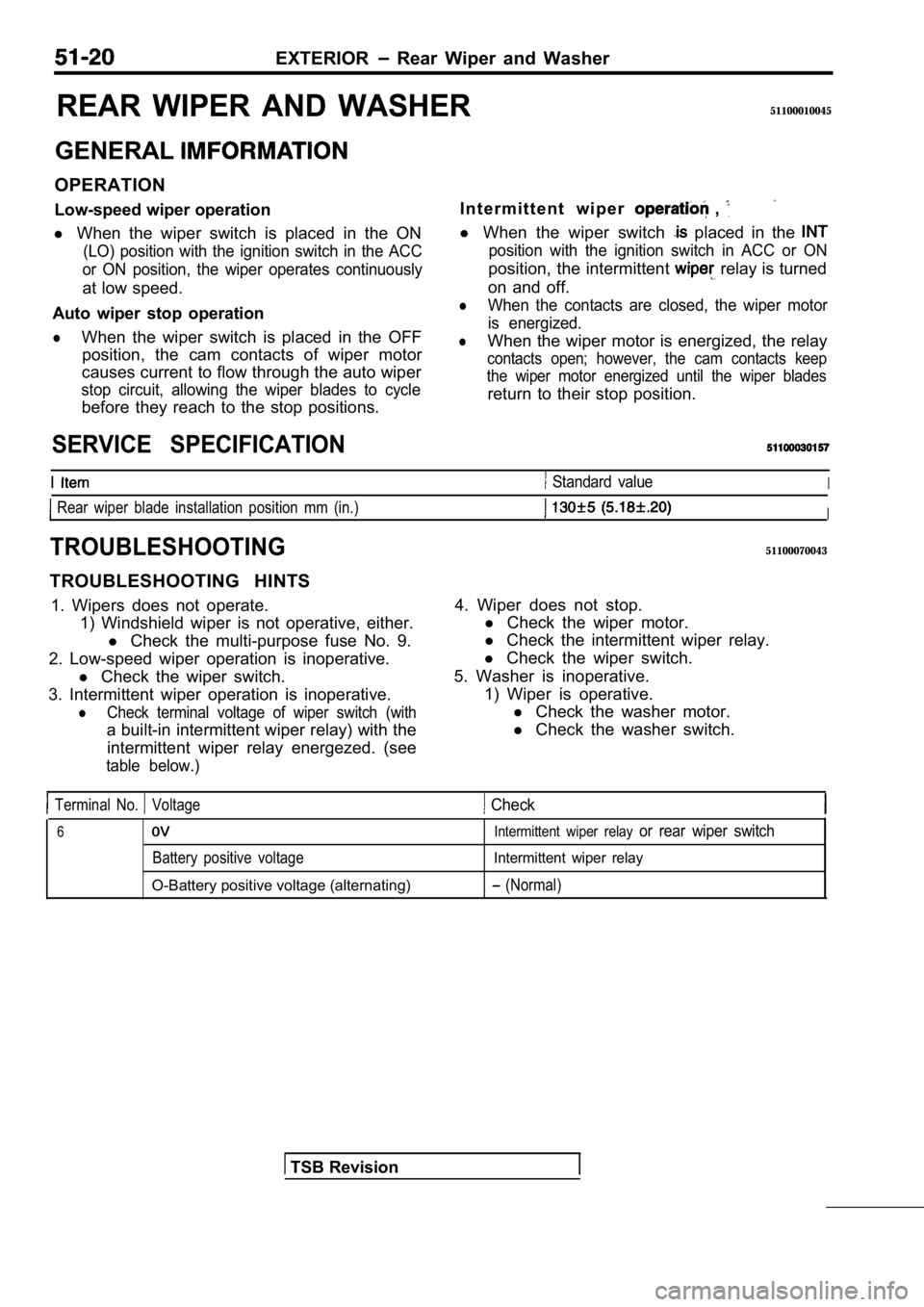
REAR WIPER AND WASHER51100010045
GENERAL
OPERATION
Low-speed wiper operationI n t e r m i t t e n t w i p e r
,
l
When the wiper switch is placed in the ON
(LO) position with the ignition switch in the ACC
or ON position, the wiper operates continuously
at low speed.
Auto wiper stop operation
lWhen the wiper switch is placed in the OFF position, the cam contacts of wiper motor
causes current to flow through the auto wiper
stop circuit, allowing the wiper blades to cycle
before they reach to the stop positions. l
When the wiper switch
placed in the
position with the ignition switch in ACC or ON
position, the intermittent relay is turned
on and off.
lWhen the contacts are closed, the wiper motor
is energized.
lWhen the wiper motor is energized, the relay
contacts open; however, the cam contacts keep
the wiper motor energized until the wiper blades
return to their stop position.
SERVICE SPECIFICATION
I Standard valueI
Rear wiper blade installation position mm (in.)I
TROUBLESHOOTING51100070043
TROUBLESHOOTING HINTS
1. Wipers does not operate. 1) Windshield wiper is not operative, either.
l Check the multi-purpose fuse No. 9.
2. Low-speed wiper operation is inoperative. l Check the wiper switch.
3. Intermittent wiper operation is inoperative.
lCheck terminal voltage of wiper switch (with
a built-in intermittent wiper relay) with the intermittent wiper relay energezed. (see
table below.)
4. Wiper does not stop. l Check the wiper motor.
l Check the intermittent wiper relay.
l Check the wiper switch.
5. Washer is inoperative. 1) Wiper is operative.l Check the washer motor.
l Check the washer switch.
Terminal No. Voltage Check
6
Battery positive voltage
O-Battery positive voltage (alternating)
Intermittent wiper relay or rear wiper switch
Intermittent wiper relay
(Normal)
TSB Revision