MITSUBISHI SPYDER 1990 Service Repair Manual
Manufacturer: MITSUBISHI, Model Year: 1990, Model line: SPYDER, Model: MITSUBISHI SPYDER 1990Pages: 2103, PDF Size: 68.98 MB
Page 1931 of 2103
E X T E R I O R
CONTENTS
AERO PARTS. . . . . . . . . . . . . . . . . . . . . . . . . . . . .11REAR BUMPER. . . . . . . . . . . . . . . . . . . . . . . . . . .4
Aero Parts . . . . . . . . . . . . . . . . . . . . . . . . . . . . . . . . . .
11REAR WIPER AND WASHER . . . . . . . . . . . . .20Sealant and Adhesive . . . . . . . . . . . . . . . . . . . . . . . .11General Information. . . . . . . . . . . . . . . . . . . . . . . . .20
DOOR MIRROR. . . . . . . . . . . . . . . . . . . . . . . . . . . 25Rear Wiper and ‘Washer. . . .. . . . . . . . . . . . . . . . .21
Door Mirror . . . . . . . . . . . . . . . . . . . . . . . . . . . . . . . . .25Service ‘Specification. . . . . . . . . . . . . . . . . . . . . . . .20
Special Tool . . . . . . . . . . . . . . . . . . . . . . . . . . . . . . . .
25Troubleshooting. . . . . . . . . . . . . . . . . . . . . . . . . . . . .20
FRONT BUMPER. . . . . . . . . . . . . . . . . . . . . . . . .2WINDSHIELD WIPER AND WASHER* . . . . . .13
6General Information. . . .. . . . . . . . . . . . . . . . . . . .13GARNISHES. . . . . . . . . . . . . . . . . . . . . . . . . . . . . .Service Specification. . . . . . . . . . . . . . . . . . . . . . . .13
MOLDINGS. . . . . . . . . . . . . . . . . . . . . . . . . . . . . . .7Troubleshooting. . . . . . . . . . . . . . . . . . . . . . . . . . . . .14
Molding. . . . . . . . . . . . . . . . . . . . . . . . . . . . . . . . . . . . .7Windshield Wiper and Washer . . .. . . . . . . . . .15
Sealant and Adhesive . . . . . . . . . . . . . . . . . . . . . . . .7
WARNINGS REGARDING SERVICING OF SUPPLEMENTAL RESTRA INT SYSTEM (SRS) EQUIPPED VEHICLES
WARNING! (1)
Improper service or maintenance of anycomponentof the SRS, or any SRS-related component, can lead to personalinjury or death to personnel (from inadvertent firing of the air bag) the the SRS inoperative). Service or maintenance of any SRS component or SRS -related component must be performed only at an authorized. MITSUBISHI dealer.(3) MITSUBISHI dealer personnel must thoroughly rev iew this manual, and especially its Supplemental
Restraint System (SRS) and GROUP 00 Maintenance Service, before beginning any service or maintenance of any
component of the SRS or any SRS-related component.
NOTE
The includes the following components: warning light, air bag module, and interconnecting wiring.Other components (that may have to be removed/installed in connection with service or maintenance) areindicated in the table of contents by an asterisk
Page 1932 of 2103
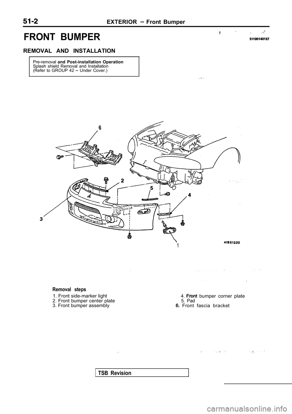
EXTERIOR Front Bumper
FRONT BUMPER
,
REMOVAL AND INSTALLATIONPre-removal and Post-installation Operation
Splash shield Removal and Installation
(Refer to GROUP 42
Under Cover.)
6
1
Removal steps
1. Front side-marker light
2. Front bumper center plate
3. Front bumper assembly 4. bumper corner plate5. Pad Front fascia bracket
TSB Revision
Page 1933 of 2103
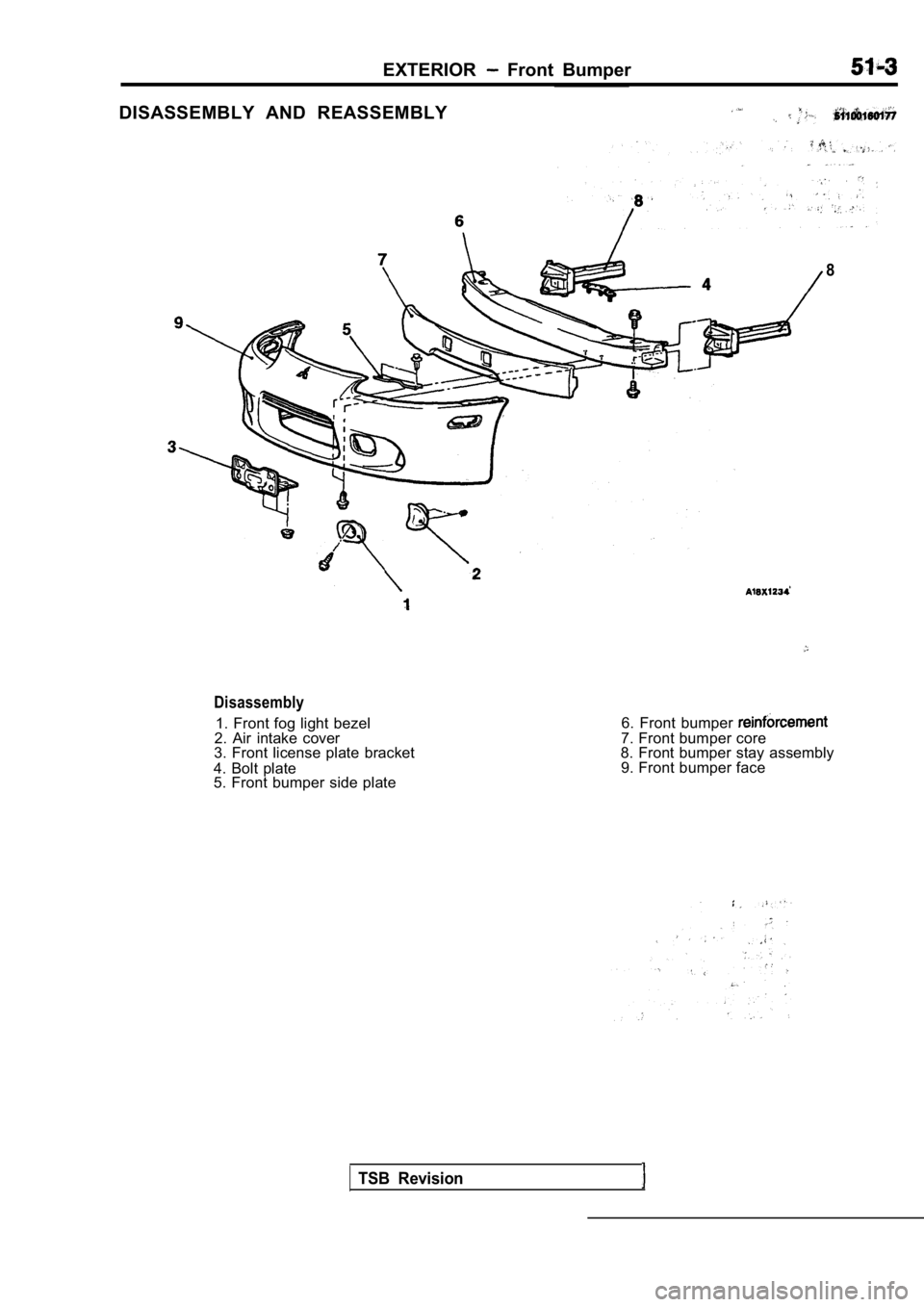
EXTERIOR Front Bumper
DISASSEMBLY AND REASSEMBLY
8
Disassembly
1. Front fog light bezel
2. Air intake cover
3. Front license plate bracket
4. Bolt plate
5. Front bumper side plate 6. Front bumper 7. Front bumper core
8. Front bumper stay assembly
9. Front bumper face
TSB Revision
Page 1934 of 2103
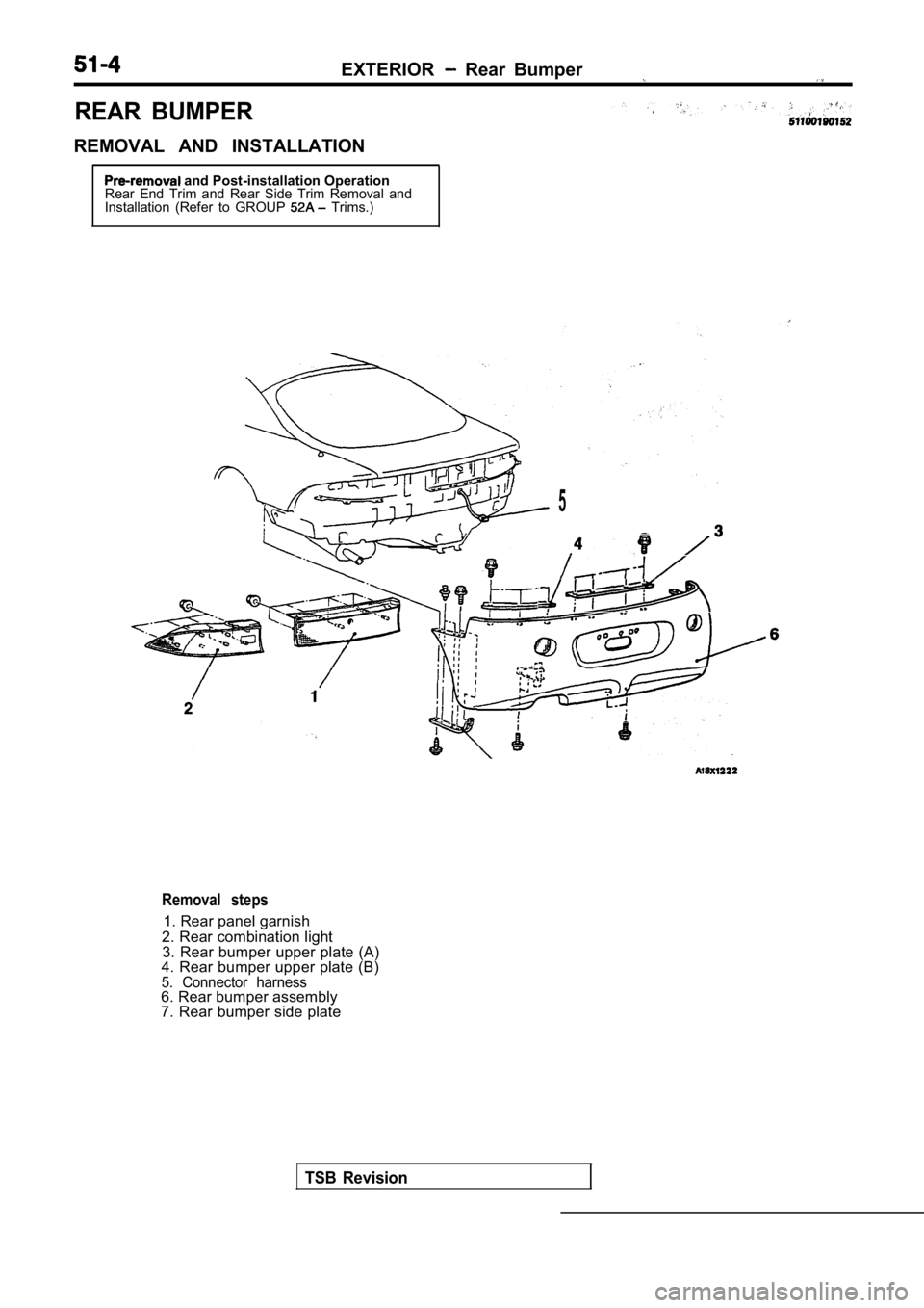
REAR BUMPER
REMOVAL AND INSTALLATION
EXTERIOR Rear Bumper
and Post-installation Operation
Rear End Trim and Rear Side Trim Removal and
Installation (Refer to GROUP
Trims.)
5
Removal steps
1. Rear panel garnish
2. Rear combination light 3. Rear bumper upper plate (A)
4. Rear bumper upper plate (B)
5. Connector harness6. Rear bumper assembly
7. Rear bumper side plate
TSB Revision
Page 1935 of 2103
EXTERIOR Rear, Bumper
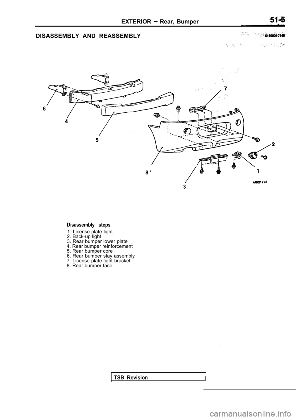
DISASSEMBLY AND REASSEMBLY
6
8 ’
3
Disassembly steps
1. License plate light
2. Back-up light
3. Rear bumper lower plate
4. Rear bumper reinforcement 5. Rear bumper core
6. Rear bumper stay assembly
7. License plate light bracket
8. Rear bumper face
TSB RevisionI
Page 1936 of 2103
51-6EXTERIOR Garnishes , .
GARNISHES
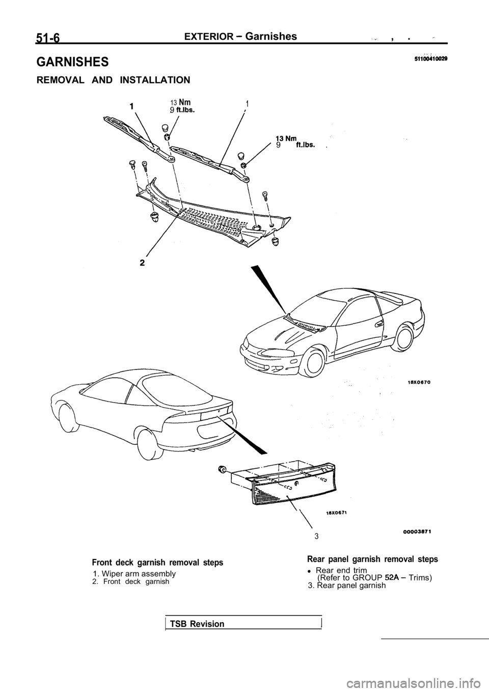
REMOVAL AND INSTALLATION
13Nm91
9 .
3
Front deck garnish removal steps
1. Wiper arm assembly
2. Front deck garnish
Rear panel garnish removal steps
l Rear end trim
(Refer to GROUP Trims)
3. Rear panel garnish
TSB Revision
Page 1937 of 2103
EXTERIOR Moldings
MOLDINGS
SEALANT AND ADHESIVE
ItemsSpecified sealant and adhesive
Side protector molding
Part No. 6382 or equivalent and
ATD Part No. 8608 Super Fast Urethane Primer or eq uivalent
MOLDINGS
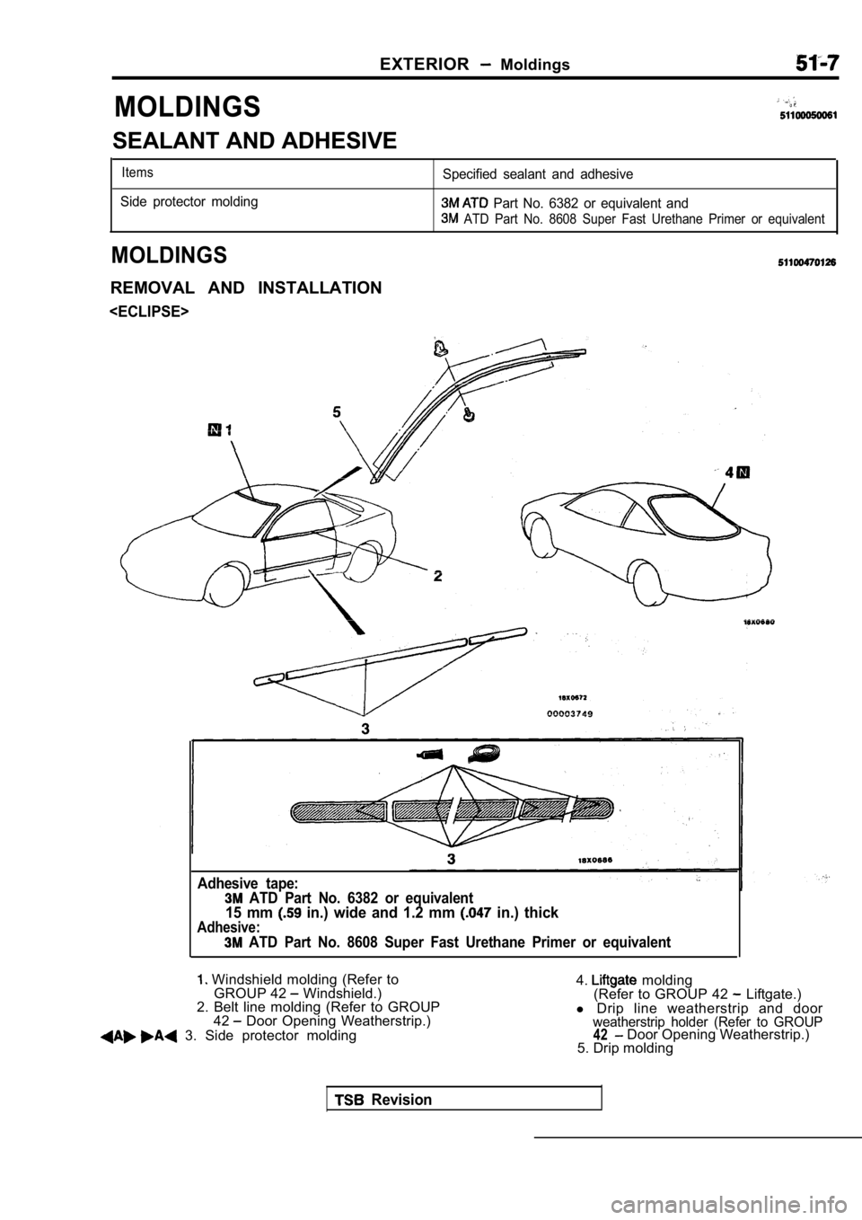
REMOVAL AND INSTALLATION
Adhesive tape:
ATD Part No. 6382 or equivalent
15 mm in.) wide and 1.2 mm in.) thick
Adhesive:
ATD Part No. 8608 Super Fast Urethane Primer or eq uivalent
Windshield molding (Refer to
GROUP 42 Windshield.)
2. Belt line molding (Refer to GROUP
42
Door Opening Weatherstrip.)
3. Side protector molding 4.
molding
(Refer to GROUP 42 Liftgate.)
l Drip line weatherstrip and door
weatherstrip holder (Refer to GROUP42 Door Opening Weatherstrip.)
5. Drip molding
Revision
Page 1938 of 2103
51-8
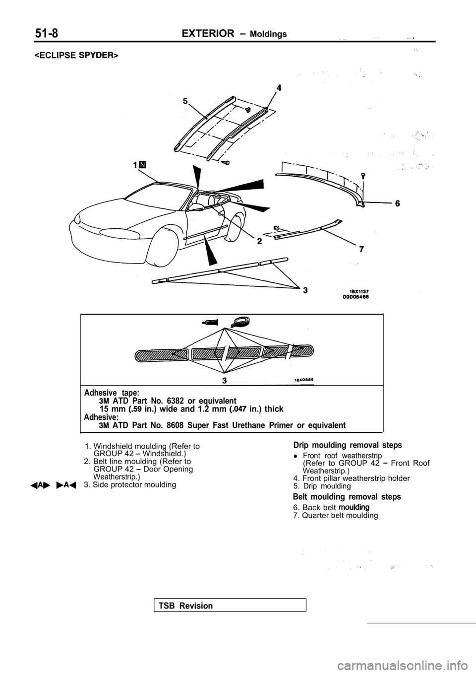
Adhesive tape:
ATD Part No. 6382 or equivalent
15 mm in.) wide and 1.2 mm in.) thick
Adhesive:
ATD Part No. 8608 Super Fast Urethane Primer or equivalent
1. Windshield moulding (Refer to
GROUP 42 Windshield.)
2. Belt line moulding (Refer to GROUP 42
Door OpeningWeatherstrip.)3. Side protector moulding
Drip moulding removal steps
l Front roof weatherstrip(Refer to GROUP 42 Front RoofWeatherstrip.)4. Front pillar weatherstrip holder5. Drip moulding
Belt moulding removal steps
6. Back belt 7. Quarter belt moulding
TSB Revision
Page 1939 of 2103
E X T E R I O R Moldings:
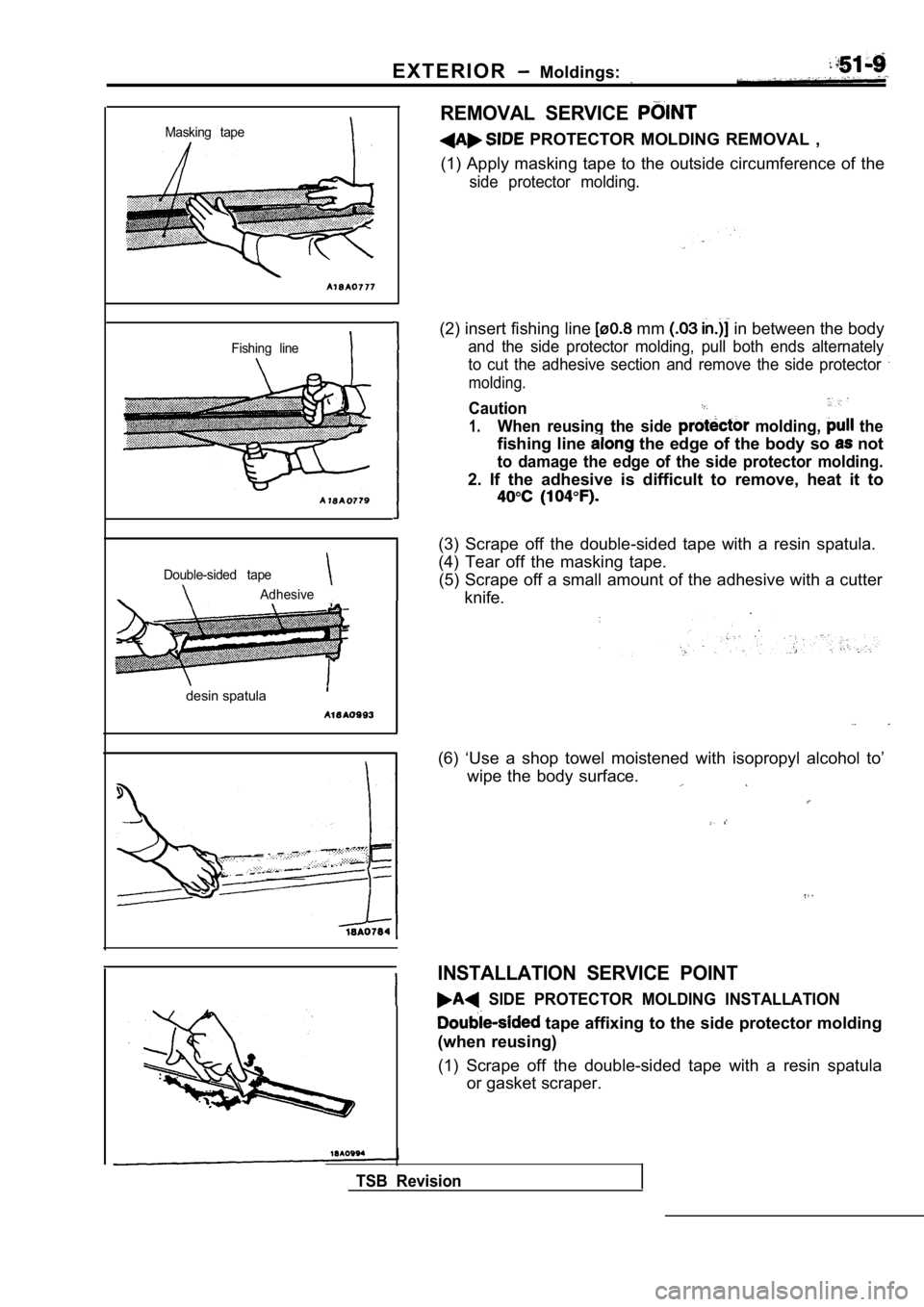
Masking tape
Fishing line
Double-sided tape
Adhesive
desin spatula
REMOVAL SERVICE
PROTECTOR MOLDING REMOVAL ,
(1) Apply masking tape to the outside circumference of the
side protector molding.
(2) insert fishing line mm in between the body
and the side protector molding, pull both ends alternately
to cut the adhesive section and remove the side pro tector
molding.
Caution
1.When reusing the side molding, the
fishing line the edge of the body so not
to damage the edge of the side protector molding.
2. If the adhesive is difficult to remove, heat it to
(3) Scrape off the double-sided tape with a resin spatula.
(4) Tear off the masking tape. (5) Scrape off a small amount of the adhesive with a cutter
knife.
(6) ‘Use a shop towel moistened with isopropyl alco hol to’
wipe the body surface.
INSTALLATION SERVICE POINT
SIDE PROTECTOR MOLDING INSTALLATION
tape affixing to the side protector molding
(when reusing)
(1) Scrape off the double-sided tape with a resin s patula
or gasket scraper.
TSB Revision
Page 1940 of 2103
EXTERIOR Moldings
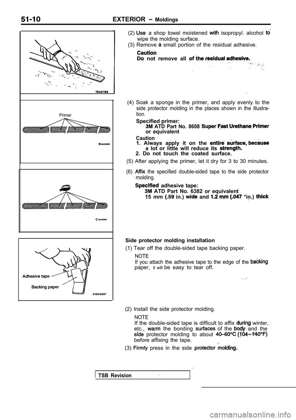
Primer
(2) a shop towel moistened isopropyl. alcohol
wipe the molding surface.
(3) Remove
small portion of the residual adhesive.
not remove all
(4) Soak a sponge in the primer, and apply evenly t o the
side protector molding in the places shown in the illustra-
tion.
Specified primer:
ATD Part No. 8608
or equivalent
Caution1. Always apply it on the
a lot or little will reduce its
2. Do not touch the coated surface.
(5) After applying the primer, let it dry for 3 to 30 minutes.
(6) the specified double-sided tape to the side protec tor
molding.
adhesive tape:
ATD Part No. 6382 or equivalent
15 mm
in.) and *in.)
Side protector molding installation
(1) Tear off the double-sided tape backing paper.
NOTE
If you attach the adhesive tape to the edge of the
paper, it will be easy to tear off.
(2) Install the side protector molding.
NOTE
If the double-sided tape is difficult to affix winter,
etc., the bonding of the and the
protector molding to about
before affixing the tape.
(3)
press in the side
TSB Revision