MITSUBISHI SPYDER 1990 Service Repair Manual
SPYDER 1990
MITSUBISHI
MITSUBISHI
https://www.carmanualsonline.info/img/19/57345/w960_57345-0.png
MITSUBISHI SPYDER 1990 Service Repair Manual
Trending: tires, air conditioning, jump start, fuses, fuse, washer fluid, clock setting
Page 1961 of 2103
INTERIOR Instrument Panel
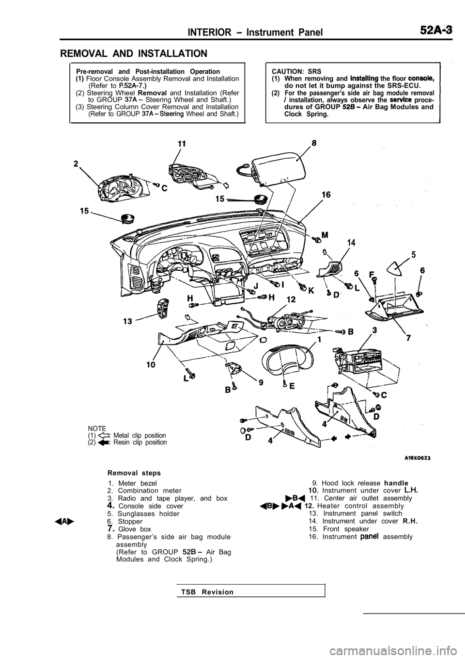
REMOVAL AND INSTALLATION
Pre-removal and Post-installation Operation Floor Console Assembly Removal and Installation(Refer to
(2) Steering Wheel Removaland Installation (Refer
to GROUP Steering Wheel and Shaft.)
(3) Steering Column Cover Removal and Installation
(Refer to GROUP Wheel and Shaft.)
CAUTION: SRS
(1) When removing and the floor do not let it bump against the SRS-ECU.(2)For the passenger’s side air bag module removal installation, always observe the proce-dures of GROUP Air Bag Modules andClock Spring.
14
5
NOTE
(1) Metal clip position
(2) Resin clip position
Removal steps
1. Meter bezel
2. Combination meter
3. Radio and tape player, and box
4. Console side cover
5. Sunglasses holder
6. Stopper 7. Glove box
8. Passenger’s side air bag module assembly(Refer to GROUP
Air Bag
Modules and Clock Spring.)
9. Hood lock release h a n d l e Instrument under cover 11. Center air outlet assembly 12. Heater control assembly
13. Instrument panel switch
14. Instrument under cover R . H .
15. Front speaker
16. Instrument
assembly
T S B R e v i s i o n
Page 1962 of 2103
INTERIOR Instrument Panel
Stopper Stopper
II
A
Lever pin
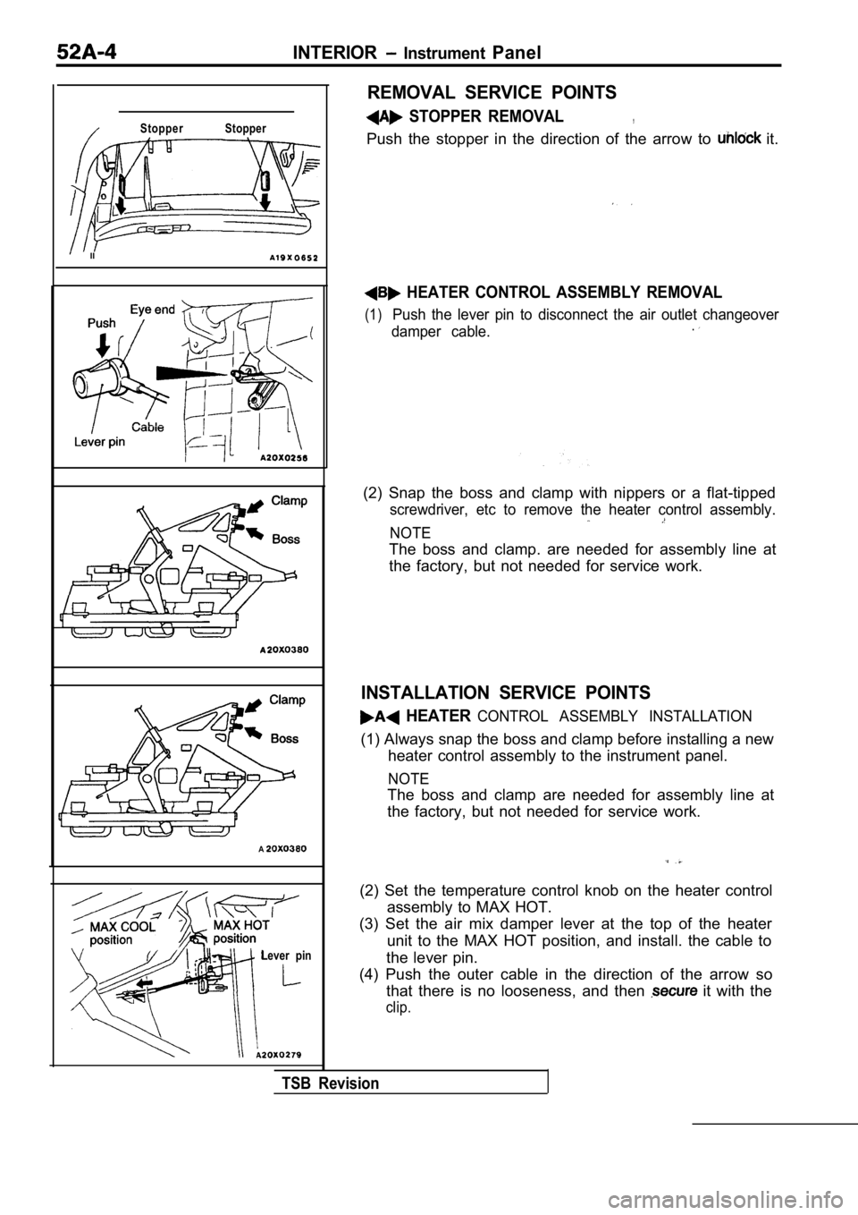
REMOVAL SERVICE POINTS
STOPPER REMOVAL,
Push the stopper in the direction of the arrow to it.
HEATER CONTROL ASSEMBLY REMOVAL
(1)Push the lever pin to disconnect the air outlet changeover
damper cable..
(2) Snap the boss and clamp with nippers or a flat- tipped
screwdriver, etc to remove the heater control assem bly.
NOTE
The boss and clamp. are needed for assembly line at
the factory, but not needed for service work.
INSTALLATION SERVICE POINTS
HEATER CONTROL ASSEMBLY INSTALLATION
(1) Always snap the boss and clamp before installing a new
heater control assembly to the instrument panel.
NOTE
The boss and clamp are needed for assembly line at
the factory, but not needed for service work.
(2) Set the temperature control knob on the heater control
assembly to MAX HOT.
(3) Set the air mix damper lever at the top of the heater
unit to the MAX HOT position, and install. the cabl e to
the lever pin.
(4) Push the outer cable in the direction of the ar row so
that there is no looseness, and then
it with the
clip.
TSB Revision
Page 1963 of 2103
INTERIOR Instrument
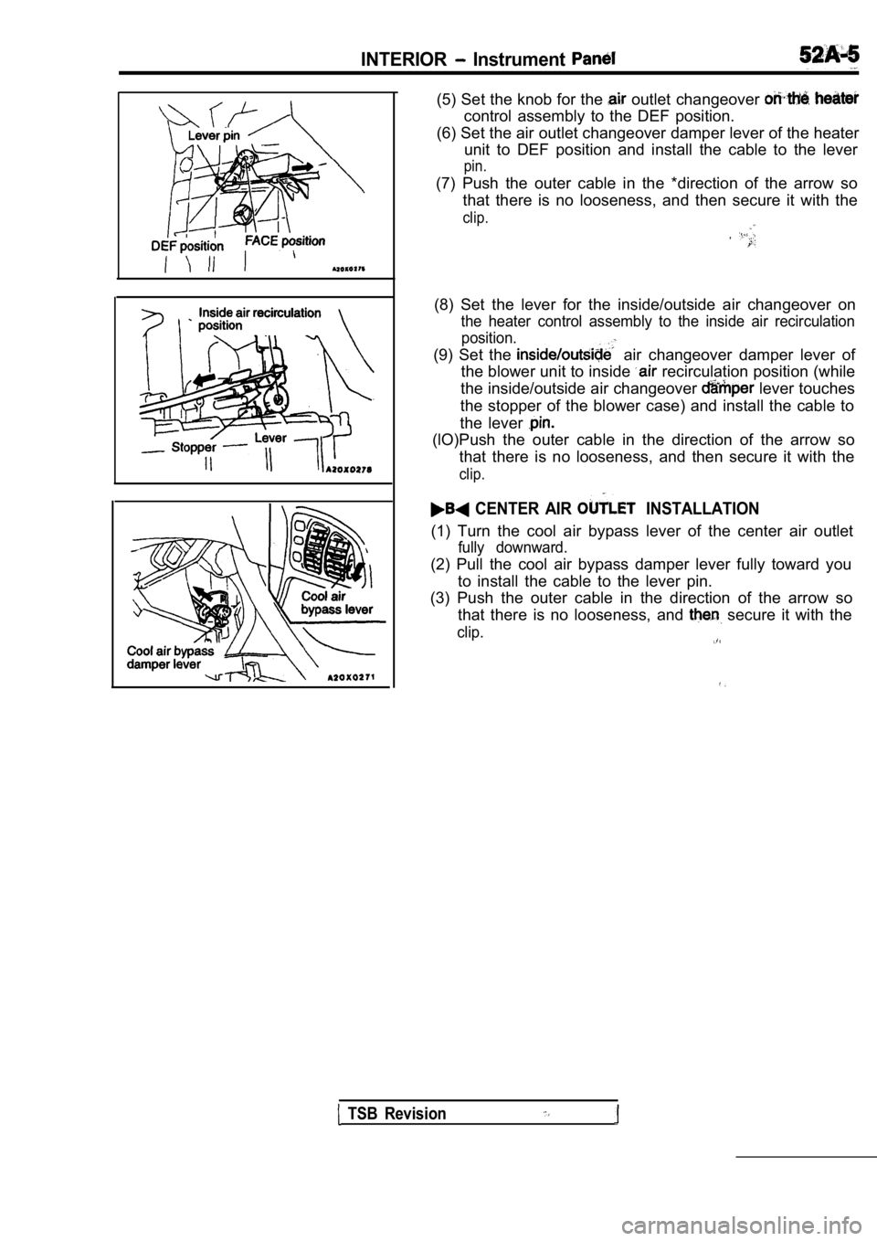
(5) Set the knob for the outlet changeover
control assembly to the DEF position.
(6) Set the air outlet changeover damper lever of t he heater
unit to DEF position and install the cable to the l ever
pin.
(7) Push the outer cable in the *direction of the a rrow so
that there is no looseness, and then secure it with the
clip.
,
(8) Set the lever for the inside/outside air changeover on
the heater control assembly to the inside air recirculation
position.
(9) Set the air changeover damper lever of
the blower unit to inside
recirculation position (while
the inside/outside air changeover
lever touches
the stopper of the blower case) and install the cab le to
the lever
(lO)Push the outer cable in the direction of the ar row so
that there is no looseness, and then secure it with the
clip.
CENTER AIR INSTALLATION
(1) Turn the cool air bypass lever of the center ai r outlet
fully downward.
(2) Pull the cool air bypass damper lever fully toward you
to install the cable to the lever pin.
(3) Push the outer cable in the direction of the ar row so
that there is no looseness, and
secure it with the
clip.
TSB Revision
Page 1964 of 2103
INTERIOR
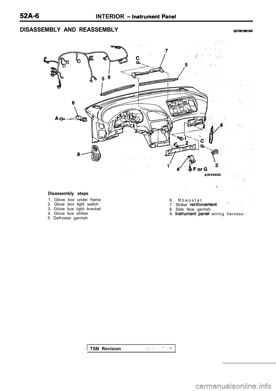
Disassembly steps
1. Glove box under frame
2. Glove box light switch
3. Glove box light bracket
4. Glove box striker
5. Defroster garnish
.
6 . R h e o s t a t
7. Striker
8. Side face garnish 9. w i r i n g h a r n e s s
DISASSEMBLY AND REASSEMBLY
TSB Revision
Page 1965 of 2103
INTERIOR Floor Console
FLOOR CONSOLE
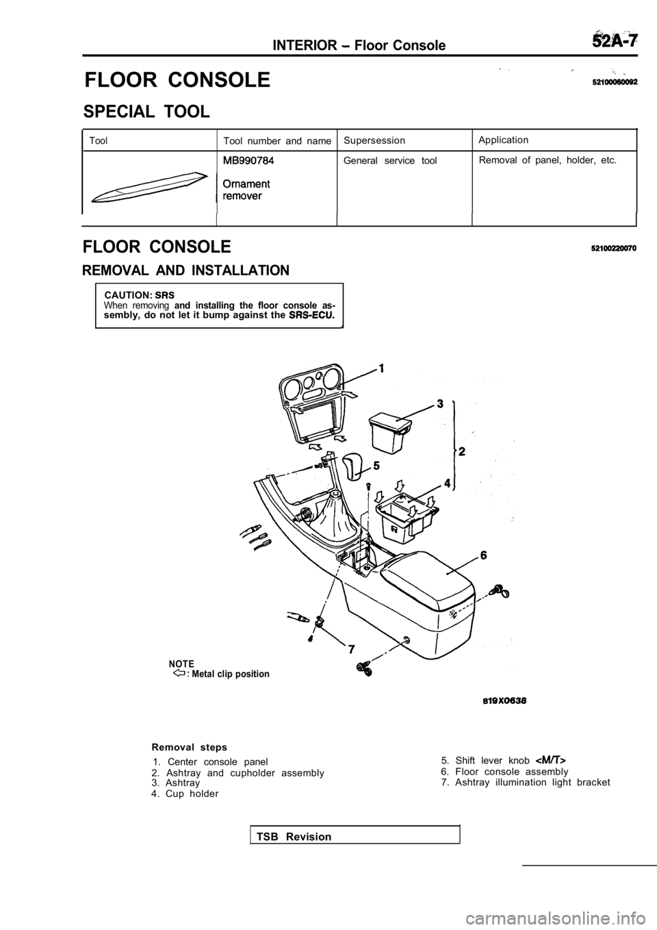
SPECIAL TOOL
ToolTool number and nameSupersession Application
General service tool Removal of panel, holder, etc.
FLOOR CONSOLE
REMOVAL AND INSTALLATION
CAUTION:When removing and installing the floor console as-sembly, do not let it bump against the
NOTE Metal clip position
Removal steps
1. Center console panel
2. Ashtray and cupholder assembly
3. Ashtray
4. Cup holder 5. Shift lever knob
6. Floor console assembly
7. Ashtray illumination light bracket
TSB Revision
Page 1966 of 2103
INTERIORFloor Console
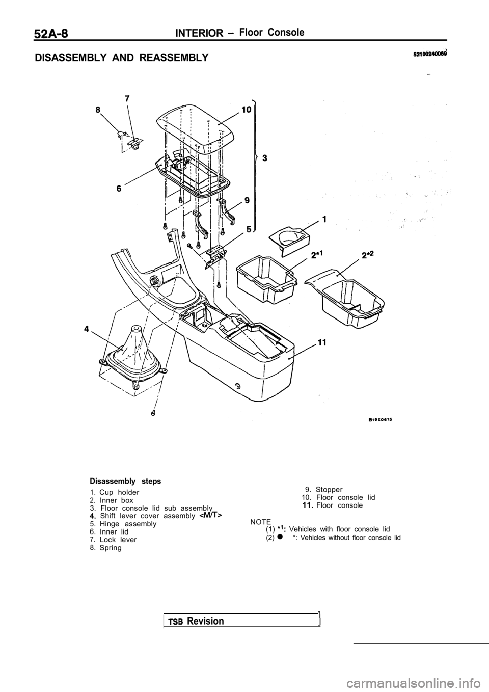
DISASSEMBLY AND REASSEMBLY
Disassembly steps
1.Cup holder2.Inner box
3. Floor console lid sub assembly
Shift lever cover assembly 5.Hinge assembly
6. Inner lid
7.Lock lever8.Spring 9. Stopper
10. Floor console lid 11. Floor console
NOTE (1)
Vehicles with floor console lid
(2)l *: Vehicles without floor console lid
Revision
Page 1967 of 2103
INTERIOR Trims
TRIMS
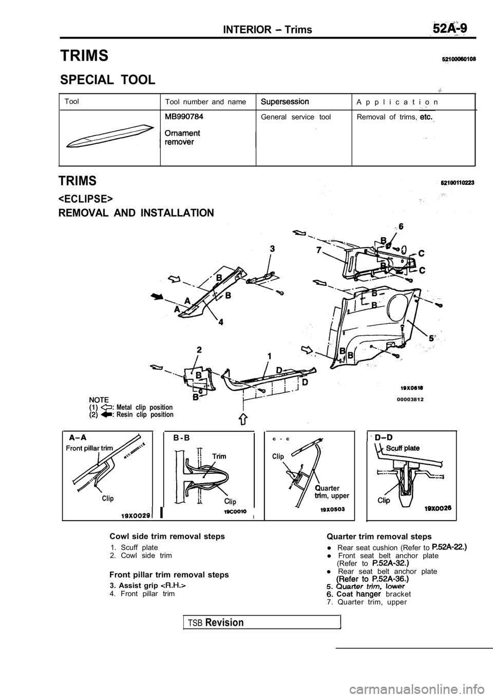
SPECIAL TOOL
ToolTool number and nameA p p l i c a t i o n
General service tool Removal of trims,
TRIMS
REMOVAL AND INSTALLATION
Metal clip position
Resin clip position
00003812
B - B
Cliplip
II
Cowl side trim removal steps 1. Scuff plate
2. Cowl side trim
Front pillar trim removal steps 3. Assist grip
4. Front pillar trim c - c
Clip
Quarter
trim, upper
Quarter trim removal steps
l Rear seat cushion (Refer to
l Front seat belt anchor plate
(Refer to
l Rear seat belt anchor plate
Coat bracket
7. Quarter trim, upper
TSBRevision
Page 1968 of 2103
INTERIOR Trims
B - B
E - E
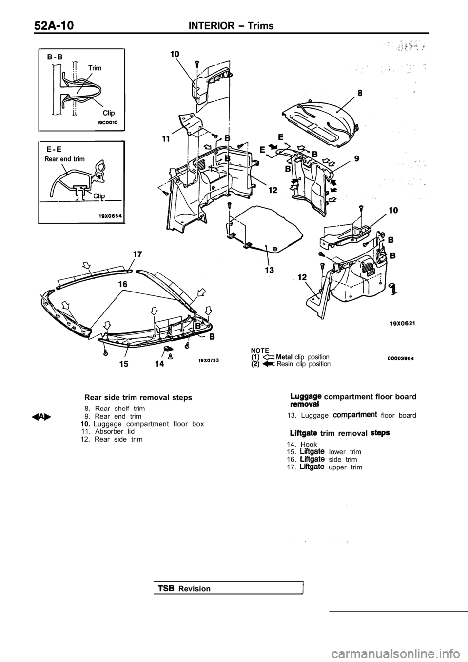
Rear end trim
Rear side trim removal steps 8. Rear shelf trim
9. Rear end trim
10. Luggage compartment floor box
11. Absorber lid
12. Rear side trim
NOTE Metal clip positionResin clip position
compartment floor board
13. Luggage
floor board
trim removal
14. Hook
15. lower trim
16. side trim
17. upper trim
Revision
Page 1969 of 2103
REMOVAL AND INSTALLATION
N O T E
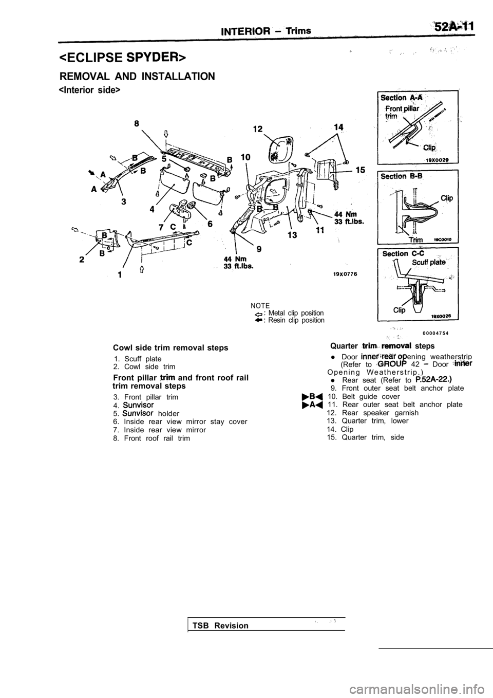
Cowl side trim removal steps1. Scuff plate
2. Cowl side trim
Front pillar
and front roof rail
trim removal steps
3. Front pillar trim
4.
5. holder
6. Inside rear view mirror stay cover
7. Inside rear view mirror
8. Front roof rail trim
Metal clip position Resin clip position
0 0 0 0 4 7 5 4
Quarter steps
l Door(Refer to ening weatherstrip
42 Door O p e n i n g W e a t h e r s t r i p . )
l Rear seat (Refer to
9. Front outer seat belt anchor plate
10. Belt guide cover 11. Rear outer seat belt anchor plate
12. Rear speaker garnish
13. Quarter trim, lower
14. Clip15. Quarter trim, side
TSB Revision
Page 1970 of 2103
INTERIOR Trims
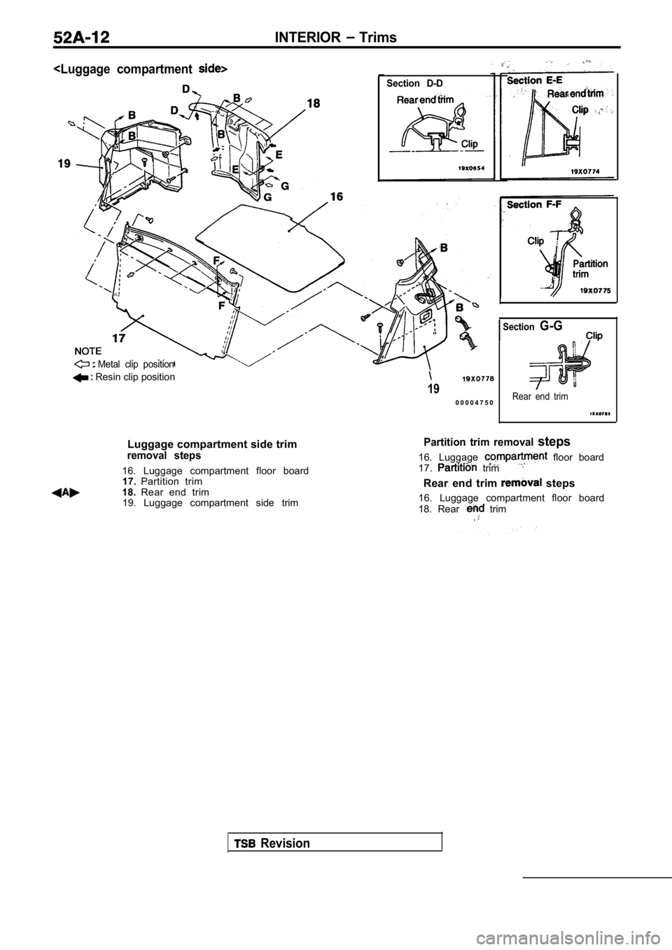
Section D-D
Metal clip position
Resin clip position
19
0 0 0 0 4 7 5 0
SectionG-G
Rear end trim
Luggage compartment side trimremoval steps
16. Luggage compartment floor board17. Partition trim
18. Rear end trim
19. Luggage compartment side trim
Partition trim removal steps
16. Luggage floor board
17. trim
Rear end trim steps
16. Luggage compartment floor board
18. Rear
trim,
Revision
Trending: spare wheel, ESP inoperative, glove box, service reset, tire type, charging, dimensions


