torque MITSUBISHI SPYDER 1990 Service Repair Manual
[x] Cancel search | Manufacturer: MITSUBISHI, Model Year: 1990, Model line: SPYDER, Model: MITSUBISHI SPYDER 1990Pages: 2103, PDF Size: 68.98 MB
Page 1323 of 2103
A U T O M A T I C T R A N S A X L E
OVERHAUL
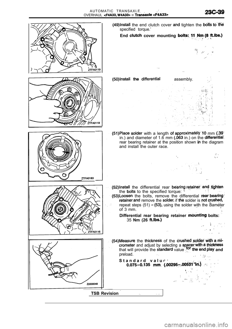
the end clutch cover tighten the
specified torque.’
End cover mounting
assembly.
with a length mm
in.) and diameter of 1.6 mm in.) on the
rear bearing retainer at the position shown the diagram
and install the outer race.
the differential rear
the to the specified torque:
the bolts, remove the differential
remove the if solder is
repeat steps (51) using the solder with the diameter
of 3 mm.
Differential rear bearing retainer bolts:
35Nm (26
,
the of the
and adjust by selecting a
that will provide the value and
preload..
S t a n d a r d v a l u e :
,,
TSB Revision
Page 1324 of 2103
AUTOMATIC TRANSAXLE
OVERHAUL
-Transaxle
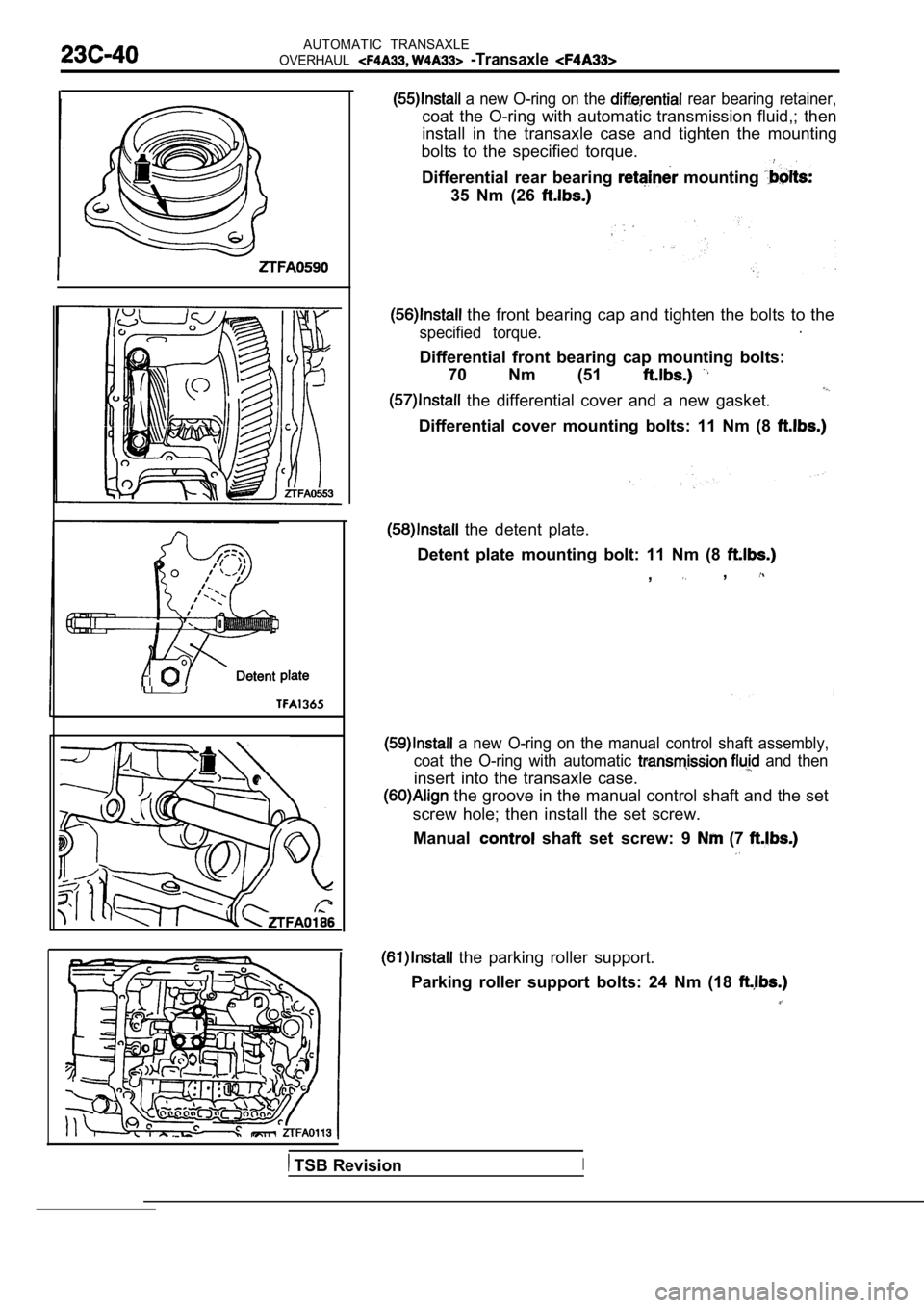
a new O-ring on the rear bearing retainer,
coat the O-ring with automatic transmission fluid,; then
install in the transaxle case and tighten the mount ing
bolts to the specified torque.
Differential rear bearing
mounting
35 Nm (26
the front bearing cap and tighten the bolts to the
specified torque..
Differential front bearing cap mounting bolts: 70 Nm (51
the differential cover and a new gasket.
Differential cover mounting bolts: 11 Nm (8
the detent plate.
Detent plate mounting bolt: 11 Nm (8
,,
a new O-ring on the manual control shaft assembly,
coat the O-ring with automatic
and then
insert into the transaxle case.
the groove in the manual control shaft and the set
screw hole; then install the set screw.
Manual
shaft set screw: 9 (7
the parking roller support.
Parking roller support bolts: 24 Nm (18
TSB RevisionI
Page 1325 of 2103
AUTOMATIC
OVERHAUL Transaxle
A
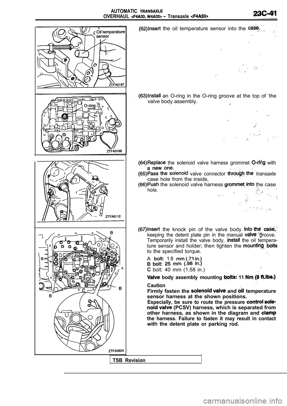
the oil temperature sensor into the
,
an O-ring in the O-ring groove at the top of ‘the
valve body assembly.
the solenoid valve harness grommet with
valve connector transaxle
case hole from the inside,
the solenoid valve harness the case
hole.
the knock pin of the valve body
keeping the detent plate pin in the manual groove.
Temporarily install the valve body,
the oil tempera-
ture sensor and holder; then tighten the
to the specified torque.
A 1 8
bolt: 40 mm (1.58 in.)
body assembly mounting 11
Caution
Firmly fasten the and temperature
sensor harness at the shown positions.
Especially, be sure to route the pressure
(PCSV) harness, which is separated from
other harness, as shown in the diagram and
the harness. Failure to fasten it may result in con tact
with the detent plate or parking rod.
TSB Revision
Page 1327 of 2103
.
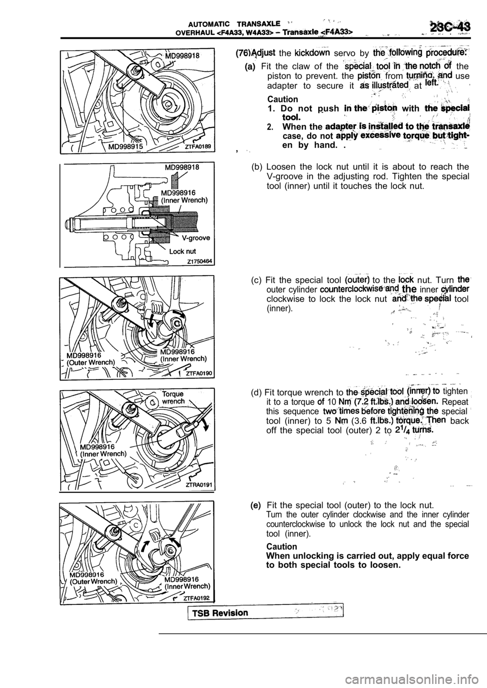
the servo by
Fit the claw of the the
piston to prevent. the
from use
adapter to secure it
at
Caution
1. Do not push with
2.When the
case, do not
en by hand. .,
(b) Loosen the lock nut until it is about to reach the
V-groove in the adjusting rod. Tighten the special
tool (inner) until it touches the lock nut.
(c) Fit the special tool
to the nut. Turn
outer cylinder the inner
clockwise to lock the lock nut tool
(inner).
(d) Fit torque wrench to tighten
it to a torque 10 Repeat
this sequence
special
tool (inner) to 5 (3.6 back
off the special tool (outer) 2 to
Fit the special tool (outer) to the lock nut.
Turn the outer cylinder clockwise and the inner cyl inder
counterclockwise to unlock the lock nut and the spe cial
tool (inner).
Caution
When unlocking is carried out, apply equal force
to both special tools to loosen.
Page 1328 of 2103
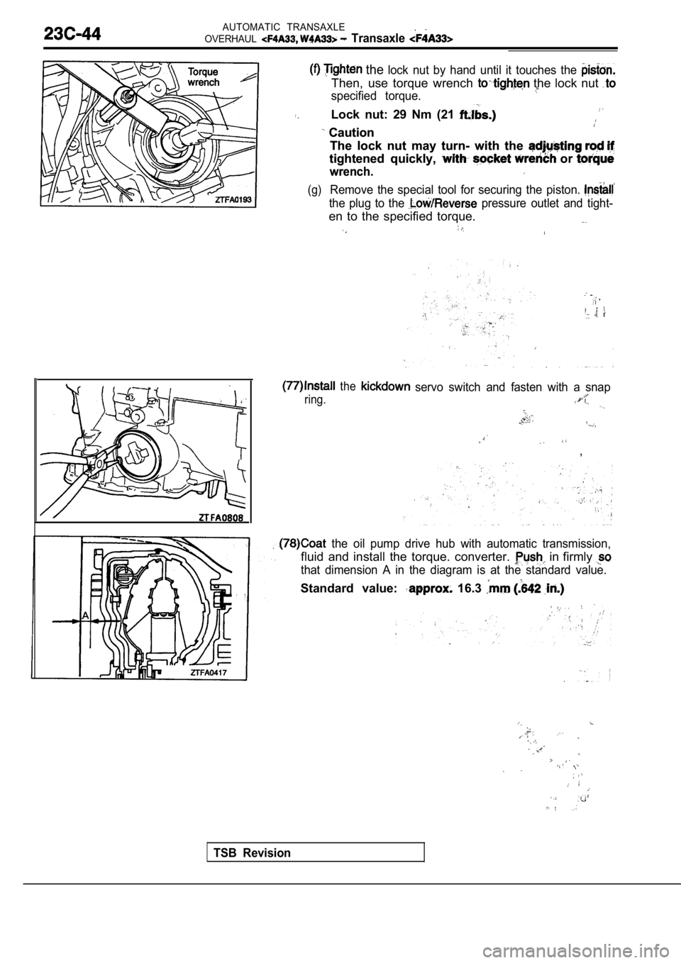
AUTOMATIC TRANSAXLE
OVERHAUL
Transaxle
the lock nut by hand until it touches the
Then, use torque wrench the lock nut
specified torque.
Lock nut: 29 Nm (21
Caution Caution
The lock nut may turn- with the The lock nut may turn- with the
tightened quickly, or tightened quickly, or
wrench.
wrench.
(g)Remove the special tool for securing the piston.
the plug to the pressure outlet and tight-
en to the specified torque.
ring. the
servo switch and fasten with a snap
,
the oil pump drive hub with automatic transmission
,
fluid and install the torque. converter. in firmly
that dimension A in the diagram is at the standard value.
Standard value: 16.3
TSB Revision
Page 1329 of 2103
-Transaxle
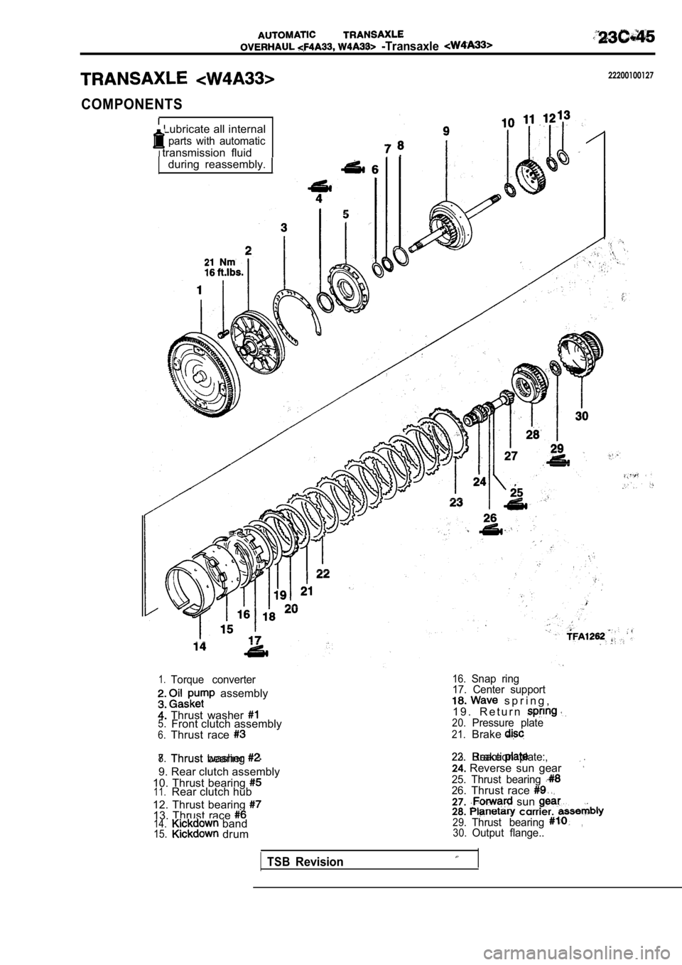
COMPONENTS
Lubricate all internal
parts with automatic
Itransmission fluid
during reassembly.
22200100127
1.Torque converter
assembly
Thrust washer 5.Front clutch assembly6.Thrust race
7.Thrust bearing 8.Thrust washer
9. Rear clutch assembly
10. Thrust bearing
11.Rear clutch hub
12. Thrust bearing
13. Thrust race 14. band15. drum
16.Snap ring
17. Center support
s p r i n g ,
1 9 . R e t u r n
20.Pressure plate
21.Brake
22.Brake23.Reaction plate:,.
24. Reverse sun gear25. Thrust bearing 26.Thrust race 27. sun 28. carrier. 29.Thrust bearing,30.Output flange..
TSBRevision
Page 1331 of 2103
A U T O M A T I C T R A N S A X L E
OVERHAUL -Transaxle
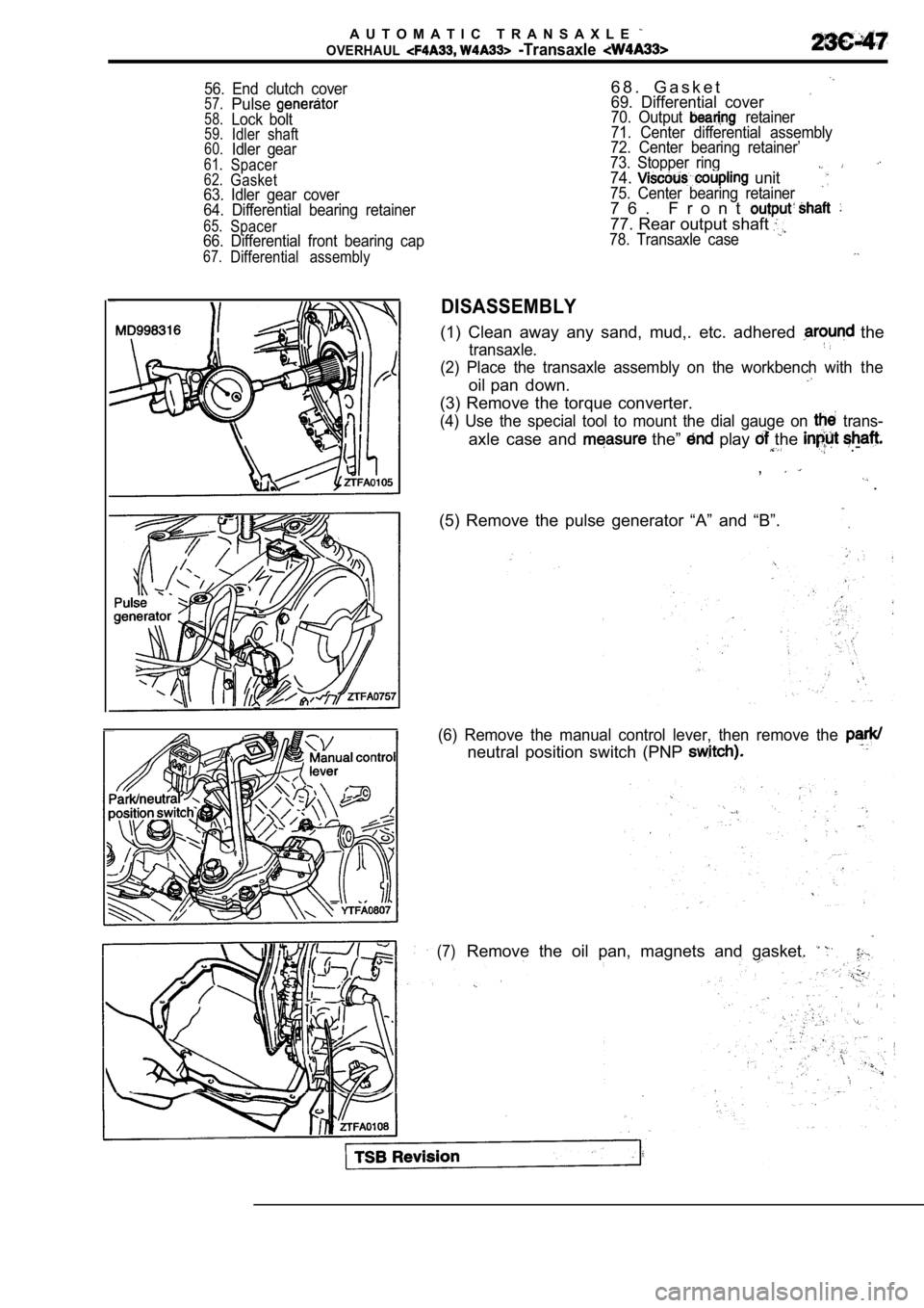
56. End clutch cover57.Pulse58.Lock bolt59.Idler shaft60.Idler gear61.Spacer62.Gasket63. Idler gear cover
64. Differential bearing retainer
65.Spacer66. Differential front bearing cap
67.Differential assembly
6 8 . G a s k e t69. Differential cover70. Output retainer
71. Center differential assembly
72. Center bearing retainer’
73. Stopper ring
74. unit75. Center bearing retainer7 6 . F r o n t
77. Rear output shaft 78. Transaxle case
DISASSEMBLY
(1) Clean away any sand, mud,. etc. adhered the
transaxle.
(2) Place the transaxle assembly on the workbench w ith the
oil pan down.
(3) Remove the torque converter.
(4) Use the special tool to mount the dial gauge on trans-
axle case and the” play the .-
,
.
(5) Remove the pulse generator “A” and “B”.
(6) Remove the manual control lever, then remove th e
neutral position switch (PNP
(7)Remove the oil pan, magnets and gasket.
Page 1342 of 2103
A U T O M A T I C T R A N S A X L E
OVERHAUL Transaxle
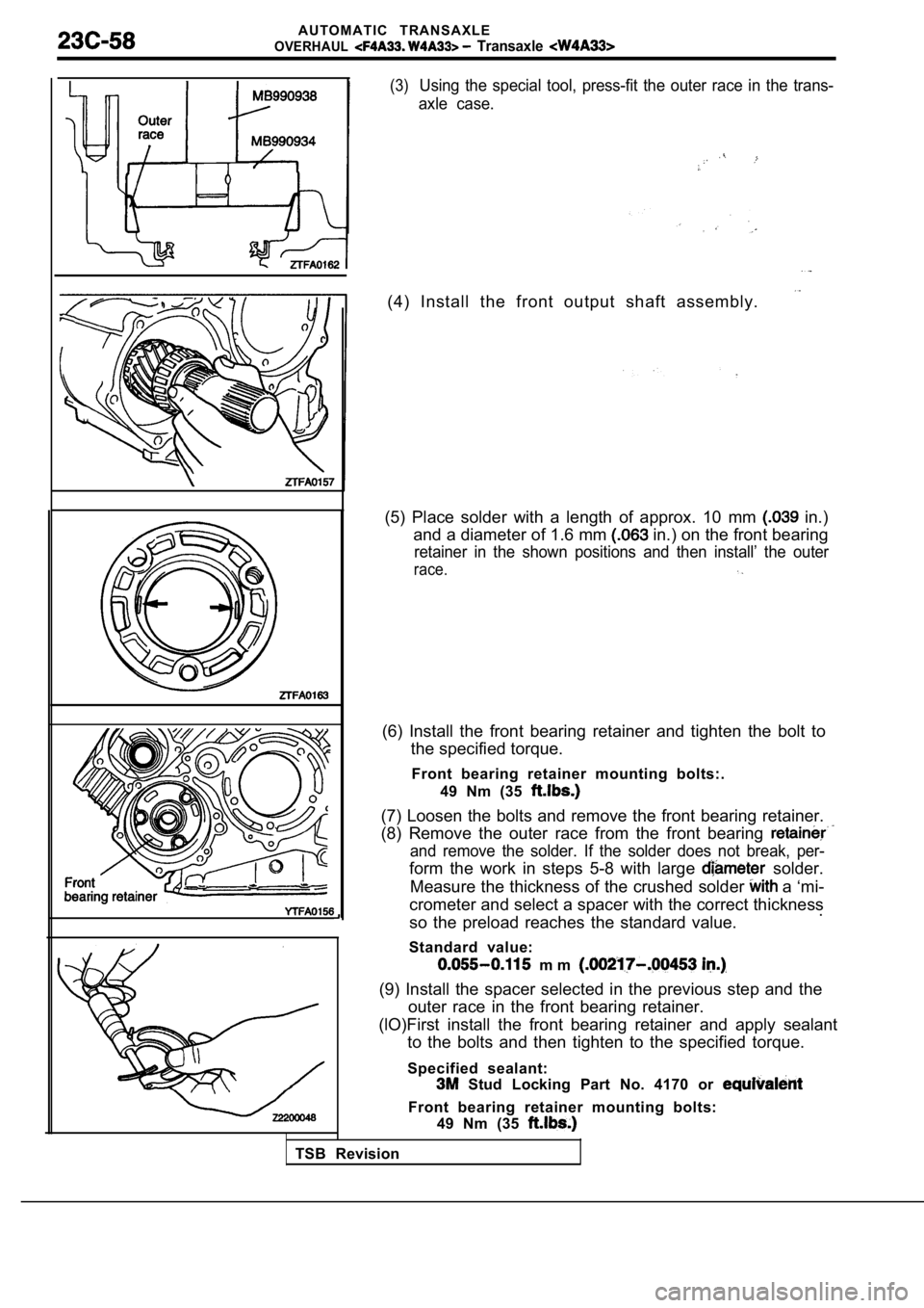
(3)Using the special tool, press-fit the outer race in the trans-
axle case.
(4) Install the front output shaft assembly.
(5) Place solder with a length of approx. 10 mm in.)
and a diameter of 1.6 mm
in.) on the front bearing
retainer in the shown positions and then install’ t he outer
race.
(6) Install the front bearing retainer and tighten the bolt to
the specified torque.
Front bearing retainer mounting bolts:. 49 Nm (35
(7) Loosen the bolts and remove the front bearing r etainer.
(8) Remove the outer race from the front bearing
and remove the solder. If the solder does not break , per-
form the work in steps 5-8 with large solder.
Measure the thickness of the crushed solder
a ‘mi-
crometer and select a spacer with the correct thick ness
so the preload reaches the standard value. .
Standard value:
m m
(9) Install the spacer selected in the previous ste p and the
outer race in the front bearing retainer.
(lO)First install the front bearing retainer and ap ply sealant
to the bolts and then tighten to the specified torq ue.
Specified sealant:
Stud Locking Part No. 4170 or
Front bearing retainer mounting bolts: 49 Nm (35
TSB Revision
Page 1344 of 2103
AUTOMATIC TRANSAXLE
OVERHAUL -Transaxle
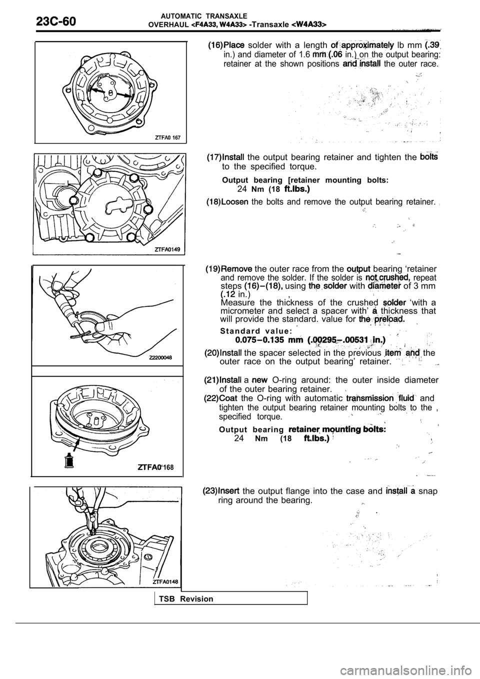
solder with a length lb mm
in.) and diameter of 1.6 in.) on the output bearing:
retainer at the shown positions
the outer race.
167
I
‘168
the output bearing retainer and tighten the
to the specified torque.
Output bearing [retainer mounting bolts: 24Nm (18
the bolts and remove the output bearing retainer.
the outer race from the bearing ‘retainer
and remove the solder. If the solder is repeat
steps using with of 3 mm
in.) ,
Measure the thickness of the crushed ‘with a
micrometer and select a spacer with’
thickness that
will provide the standard. value for
S t a n d a r d v a l u e :
. . .
the spacer selected in the previous the
outer race on the output bearing’ retainer.
a O-ring around: the outer inside diameter
of the outer bearing retainer.
the O-ring with automatic and
tighten the output bearing retainer mounting bolts to the ,
specified torque.
Output bearing
24 Nm (18
the output flange into the case and snap
ring around the bearing.
.
TSB Revision
Page 1352 of 2103
A U T O M A T I C T R A N S A X L E
OVERHAUL -Transaxle
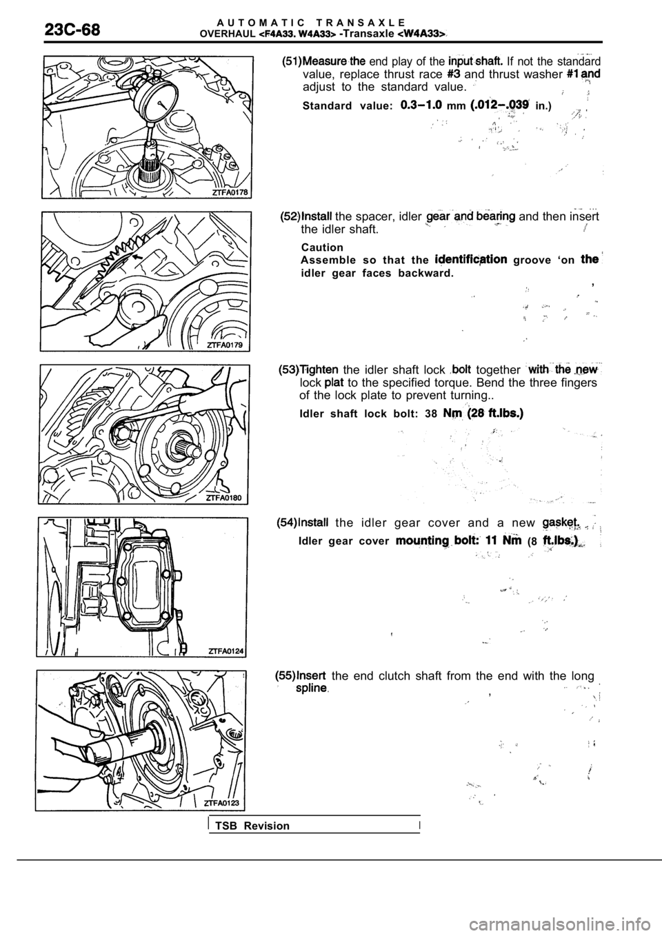
end play of the If not the standard
value, replace thrust race and thrust washer
adjust to the standard value.
Standard value: mm in.)
. . . the spacer, idler and then insert
the idler shaft.
Caution
Assemble so that the
groove ‘on
idler gear faces backward. ,
the idler shaft lock together
lock to the specified torque. Bend the three fingers
of the lock plate to prevent turning..
Idler shaft lock bolt: 38
the idler gear cover and a new
Idler gear cover(8
the end clutch shaft from the end with the long
.,
TSB RevisionI