torque MITSUBISHI SPYDER 1990 Service Repair Manual
[x] Cancel search | Manufacturer: MITSUBISHI, Model Year: 1990, Model line: SPYDER, Model: MITSUBISHI SPYDER 1990Pages: 2103, PDF Size: 68.98 MB
Page 1388 of 2103
AUTOMATIC TRANSAXLE
. .
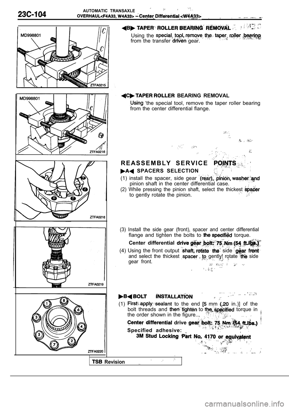
Using the
from the transfer gear.
BEARING REMOVAL
‘the special tool, remove the taper roller bearing
from the center differential flange.
R E A S S E M B L Y S E R V I C E
SPACERS SELECTION
(1) install the spacer, side gear
pinion shaft in the center differential case.
(2) While pressing the pinion shaft, select the thi ckest
to gently rotate the pinion.
(3) Install the side gear (front), spacer and cente r differential
flange and tighten the bolts to torque.
Center differential
(4) Using the front output side
and select the thickest , gently! rotate side
gear front.
.
(1) to the end mm in.)] of the
bolt threads and
to torque in
the order shown in the figure..,
.. . .
drive
Specified adhesive:
,
Revision
Page 1392 of 2103
AUTOMATIC TRANSAXLE
Transfer .
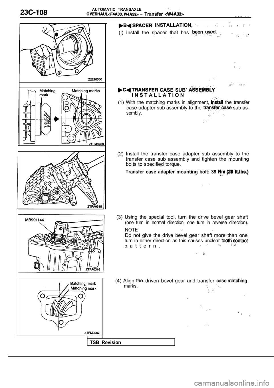
INSTALLATION,
(I) Install the spacer that has
CASE SUB’
I N S T A L L A T I O N
(1) With the matching marks in alignment, the transfer
case adapter sub assembly to the sub as-
sembly.
(2) Install the transfer case adapter sub assembly to the
transfer case sub assembly and tighten the mounting bolts to specified torque.
Transfer case adapter mounting bolt: 39
(3) Using the special tool, turn the drive bevel ge ar shaft
(one turn in normal direction, one turn in reverse direction).
NOTE
Do not give the drive bevel gear shaft more than on e
turn in either direction as this causes unclear
p a t t e r n .
Matching mark
mark(4) Align driven bevel gear and transfer
marks.
. ,
TSB Revision
Page 1398 of 2103
AUTOMATIC TRANSAXLE
Transfer Case Adapter
2
Matching mark
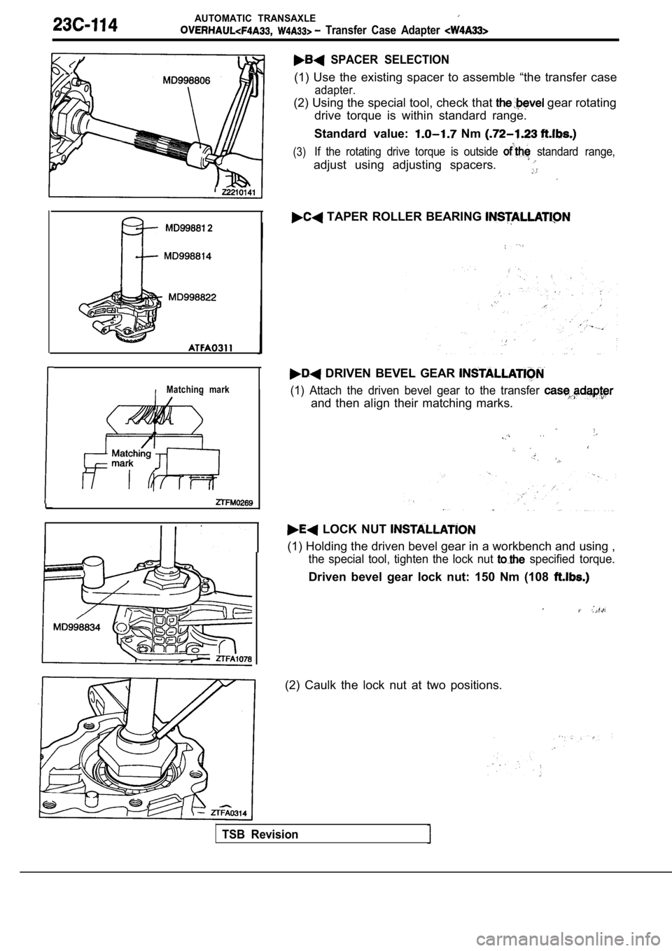
SPACER SELECTION
(1) Use the existing spacer to assemble “the transfer case
adapter.
(2) Using the special tool, check that gear rotating
drive torque is within standard range.
Standard value:
Nm
(3)If the rotating drive torque is outside standard range,
adjust using adjusting spacers.
TAPER ROLLER BEARING
DRIVEN BEVEL GEAR
(1) Attach the driven bevel gear to the transfer
and then align their matching marks.
. .
LOCK NUT
(1) Holding the driven bevel gear in a workbench an d using ,
the special tool, tighten the lock nut specified torque.
Driven bevel gear lock nut: 150 Nm (108
(2) Caulk the lock nut at two positions.
TSB Revision
Page 1401 of 2103
AUTOMATIC TRANSAXLE
Transfer Case
S E A L
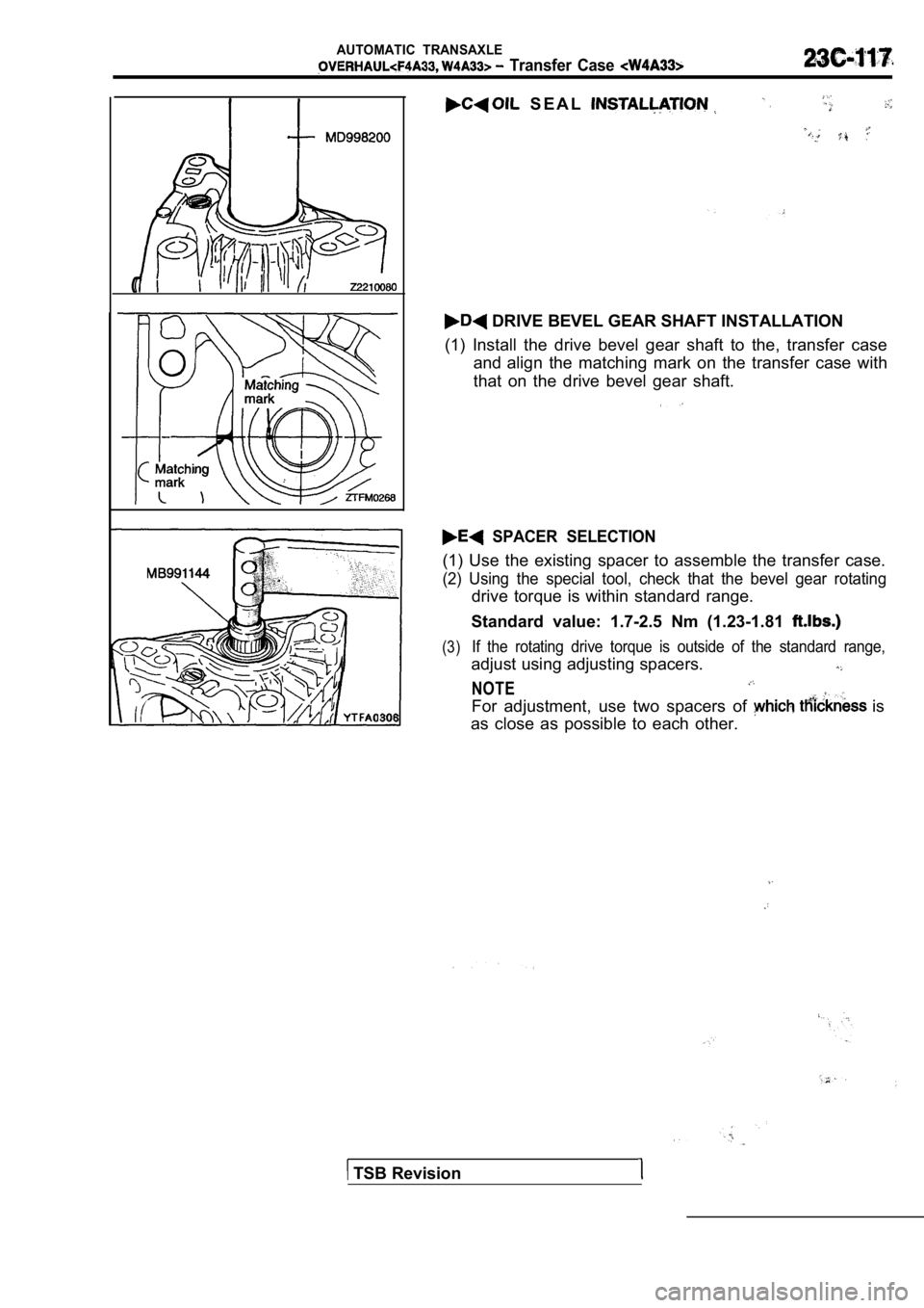
DRIVE BEVEL GEAR SHAFT INSTALLATION
(1) Install the drive bevel gear shaft to the, tran sfer case
and align the matching mark on the transfer case wit h
that on the drive bevel gear shaft.
SPACER SELECTION
(1) Use the existing spacer to assemble the transfe r case.
(2) Using the special tool, check that the bevel gear rotating
drive torque is within standard range.
Standard value: 1.7-2.5 Nm (1.23-1.81
(3)If the rotating drive torque is outside of the stan dard range,
adjust using adjusting spacers.
NOTE
For adjustment, use two spacers of is
as close as possible to each other.
TSB Revision
Page 1403 of 2103
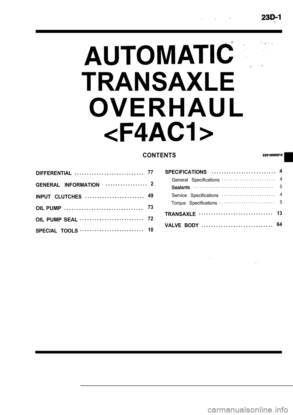
TRANSAXLE
O V E R H A U L
CONTENTS
DIFFERENTIAL77SPECIFICATIONS. . . . . . . . . . . . . . . . . . . . . . . . . .4. . . . . . . . . . . . . . . . . . . . . . . . . . . .. . . . . . . . . . . . . . . . .
2General Specifications. . . . . . . . . . . . . . . . . . . . . . . .4
GENERAL INFORMATION. . . . . . . . . . . . . . . . . . . . . . . . . . . . . . . . . . . .5
INPUT CLUTCHES49Service Specifications. . . . . . . . . . . . . . . . . . . . . . . .4. . . . . . . . . . . . . . . . . . . . . . . .
Torque Specifications. . . . . . . . . . . . . . . . . . . . . . . . .5
OIL PUMP. . . . . . . . . . . . . . . . . . . . . . . . . . . . . . . .73
TRANSAXLE. . . . . . . . . . . . . . . . . . . . . . . . . . . . . .13
OIL PUMP SEAL . . . . . . . . . . . . . . . . . . . . . . . . . .72
VALVE BODY. . . . . . . . . . . . . . . . . . . . . . . . . . . . .64
SPECIAL TOOLS. . . . . . . . . . . . . . . . . . . . . . . . . .10
Page 1404 of 2103
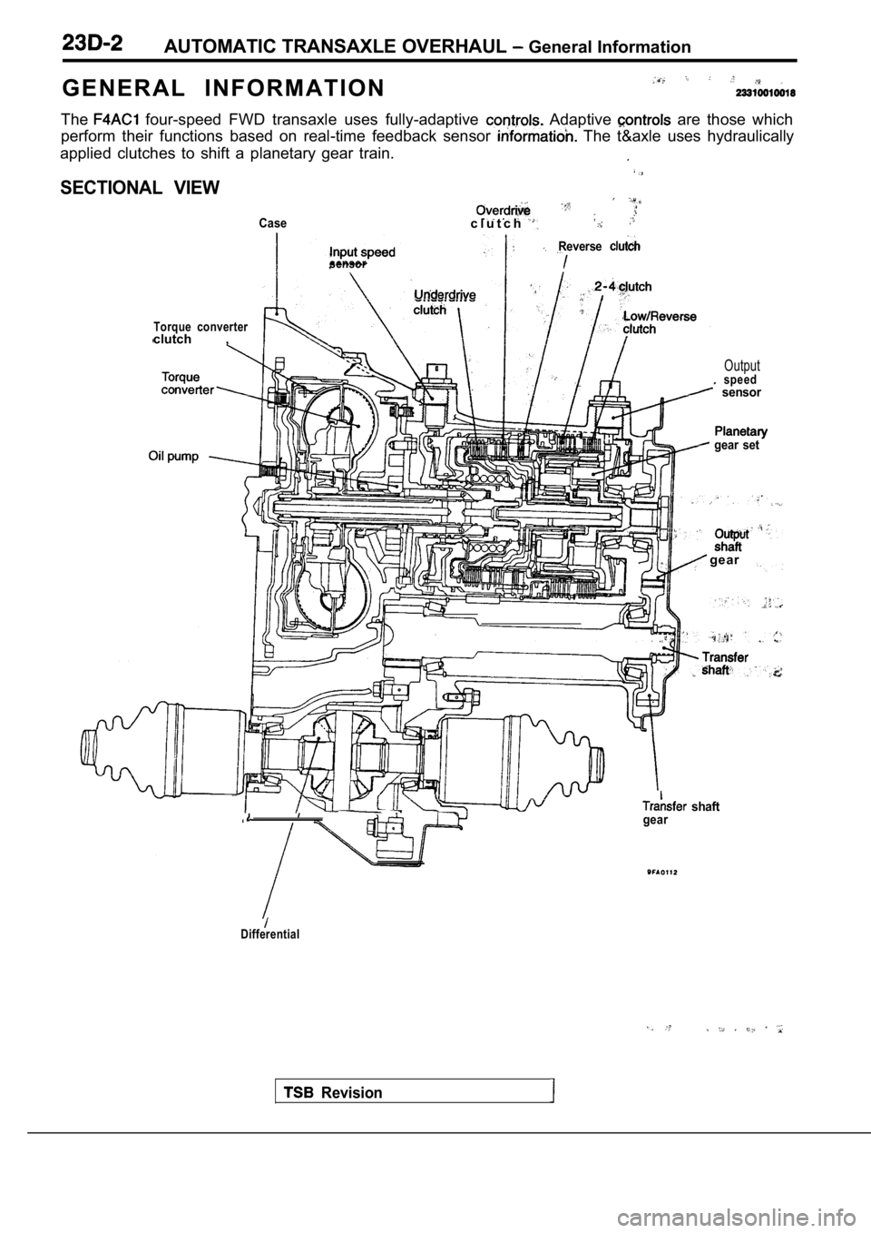
AUTOMATIC TRANSAXLE OVERHAUL General Information
G E N E R A L I N F O R M A T I O N
The four-speed FWD transaxle uses fully-adaptive Adaptive are those which
perform their functions based on real-time feedback sensor
The t&axle uses hydraulically
applied clutches to shift a planetary gear train.
SECTIONAL VIEW
Casec l u t c h
sensor
Torque converterclutch ,
Reverse
Outputspeed sensor
gear set
Revision
gear
shaftgear
Differential
Page 1405 of 2103
AUTOMATIC ‘TRANSAXLE OVERHAUL
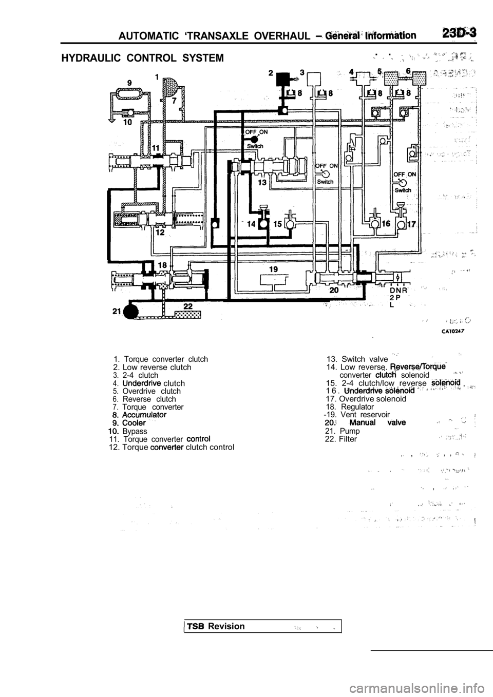
HYDRAULIC CONTROL SYSTEM. .
1. Torque converter clutch2. Low reverse clutch3.2-4 clutch4. clutch5.Overdrive clutch6.Reverse clutch7.Torque converter
Bypass
11. Torque converter
12. Torque clutch control
13. Switch valve 14. Low reverse, converter solenoid15. 2-4 clutch/low reverse , 1 6 .17. Overdrive solenoid18. Regulator
-19. Vent reservoir
21. Pump22. Filter
, , ,
,
Revision
Page 1406 of 2103
AUTOMATIC TRANSAXLE OVERHAUL
. ..
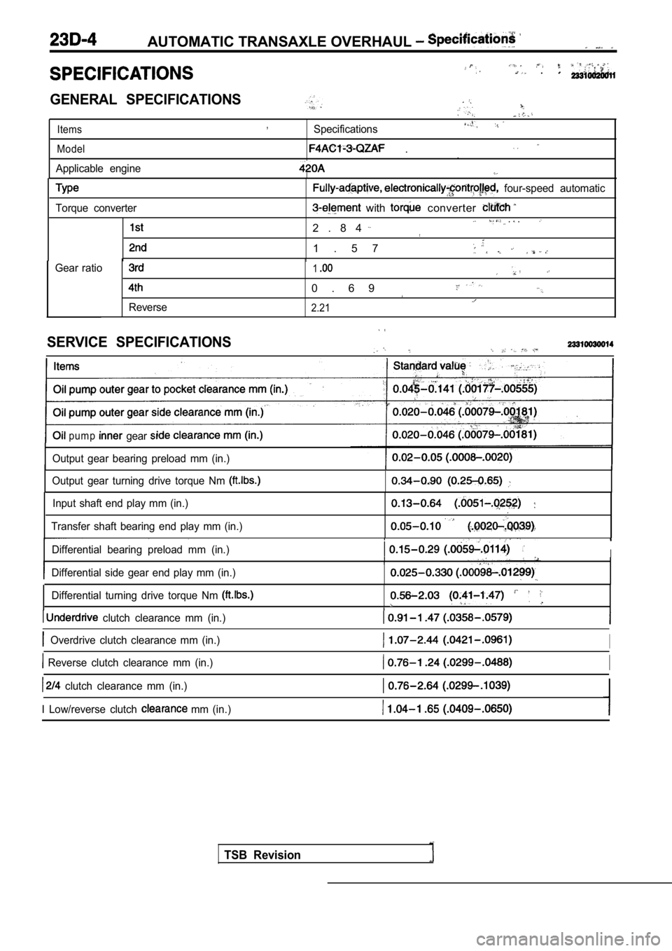
GENERAL SPECIFICATIONS
Items,Specifications
Model
Applicable engine
..
Torque converter
four-speed automatic
with converter
2 . 8 4 . .
1 . 5 7
Gear ratio
Reverse
1
0 . 6 9
2.21
SERVICE SPECIFICATIONS
p u m p gear
Output gear bearing preload mm (in.)
Output gear turning drive torque Nm
Input shaft end play mm (in.)
Transfer shaft bearing end play mm (in.)
Differential bearing preload mm (in.)I
Differential side gear end play mm (in.)
Differential turning drive torque Nm
clutch clearance mm (in.)
Overdrive clutch clearance mm (in.)I
Reverse clutch clearance mm (in.)I
clutch clearance mm (in.)
I Low/reverse clutch
mm (in.)
TSB Revision
Page 1407 of 2103
AUTOMATIC TRANSAXLE OVERHAUL
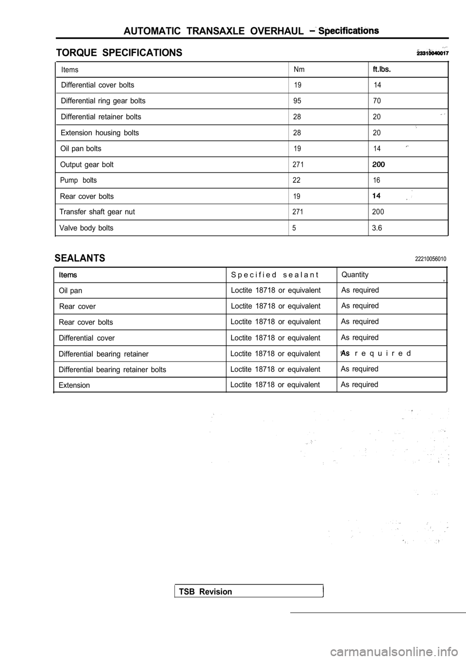
TORQUE SPECIFICATIONS
Items
Differential cover bolts
Differential ring gear bolts
Differential retainer bolts
Extension housing bolts
Oil pan bolts
Output gear bolt
Pump bolts
Rear cover bolts
Transfer shaft gear nut
Valve body bolts
Nm
19
95
28
28
19
271
22
19
271
5
14
70
20
20
14
16
200
3.6
SEALANTS
Oil pan Rear cover
Rear cover bolts
Differential cover
Differential bearing retainer
Differential bearing retainer bolts
Extension
S p e c i f i e d s e a l a n t
Loctite 18718 or equivalent
Loctite 18718 or equivalent
Loctite 18718 or equivalent
Loctite 18718 or equivalent
Loctite 18718 or equivalent
Loctite 18718 or equivalent
Loctite 18718 or equivalent
22210056010
Quantity,
As required
As required
As required
As required
r e q u i r e d
As required
As required
TSB Revision
Page 1436 of 2103
AUTOMATICTRANSAXLE,,
W r
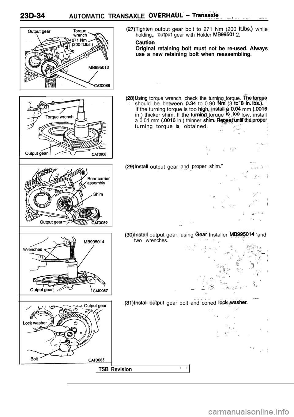
output gear bolt to 271 Nm (200 while
holding,. gear with Holder 2.
Original retaining bolt must not be re-used. Alwaysuse a new retaining bolt when reassembling.
torque wrench, check the turning torque.
should be between to 0.90 (3
If the turning torque is too mm
in.) thicker shim. If the torque low, install
a 0.04 mm in.) thinner
turning torque obtained.
output gearand
TSB Revision. .
proper shim.”
,
output gear, using Installer ‘and
two wrenches.
-- ,
. ,I
. . , .
.
_ _..
. .
gear bolt and coned
,
,