ENGINE (TURBO)
AND
ENGINE> Troubleshooting
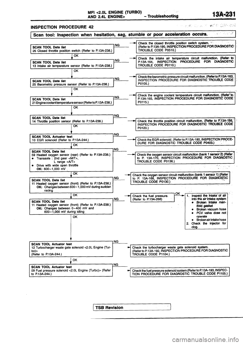
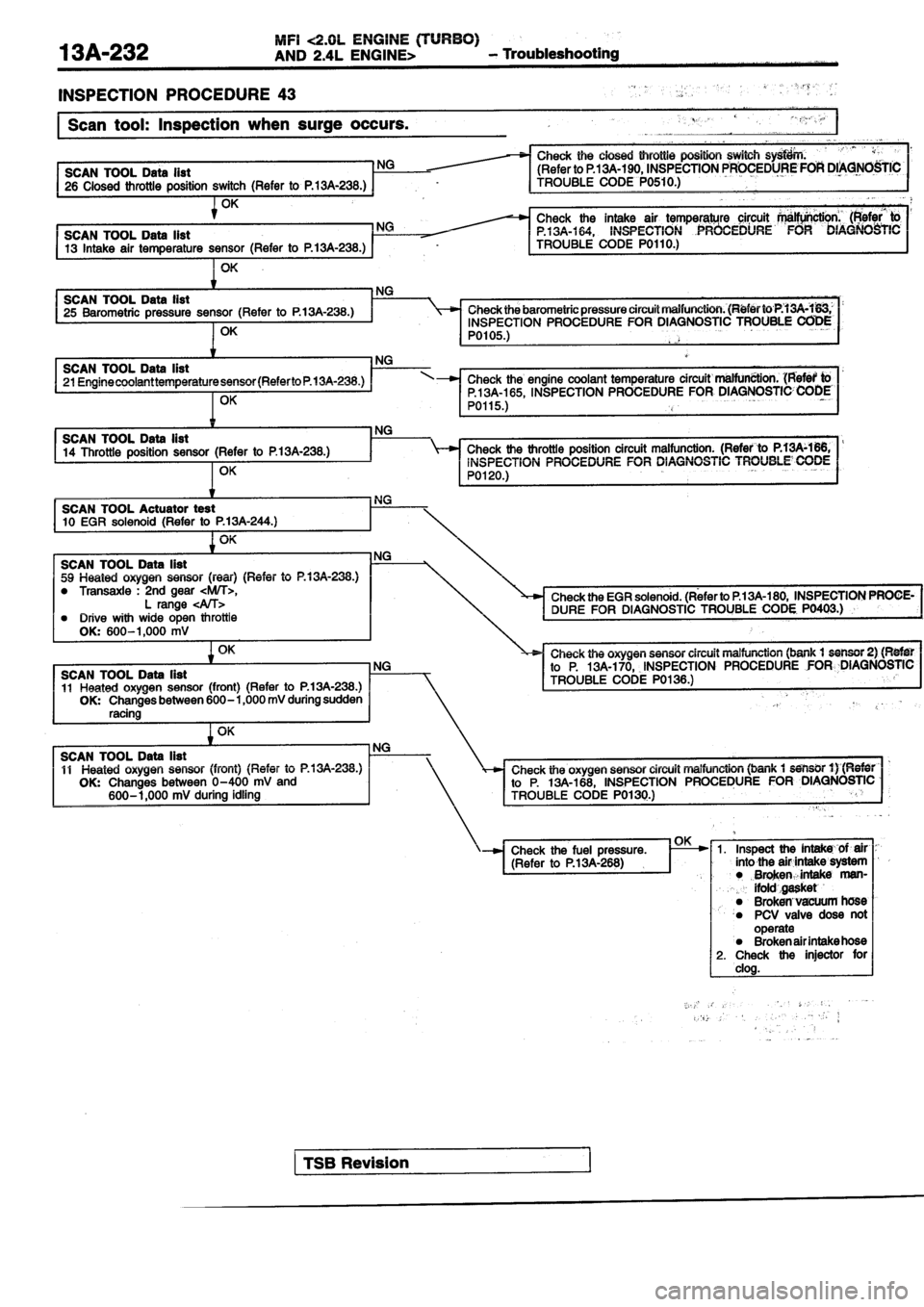
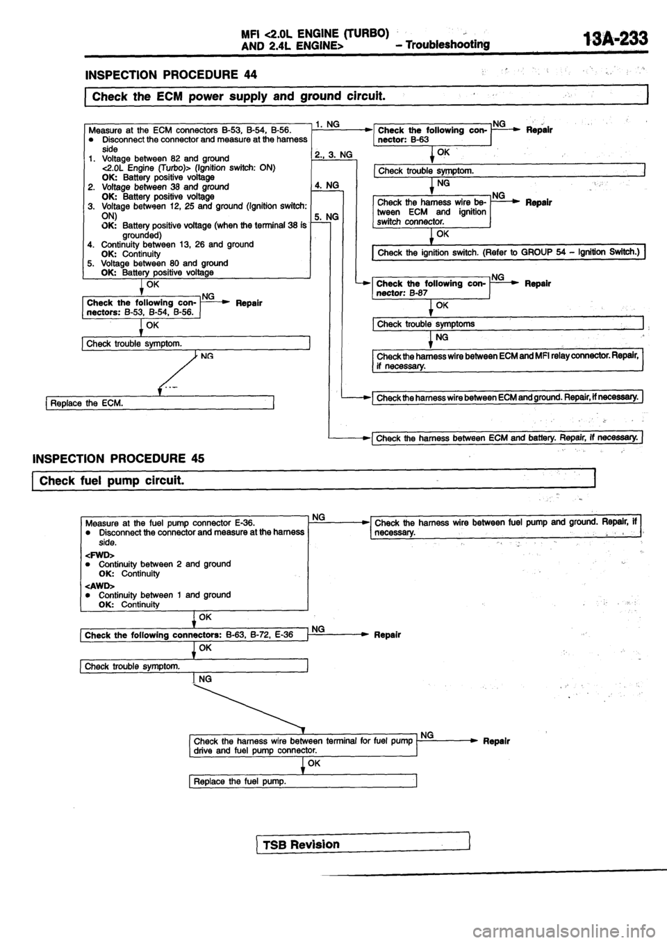
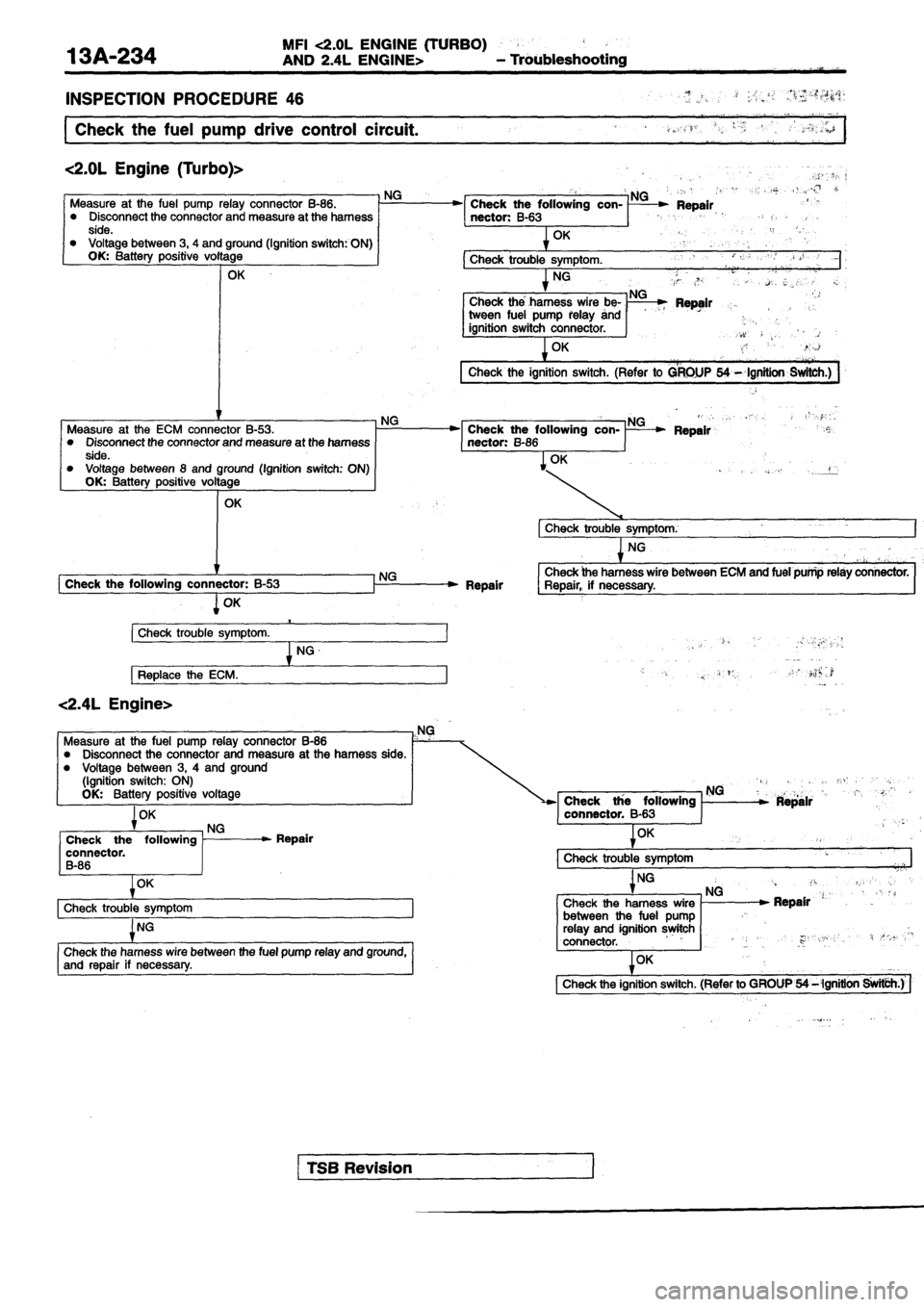
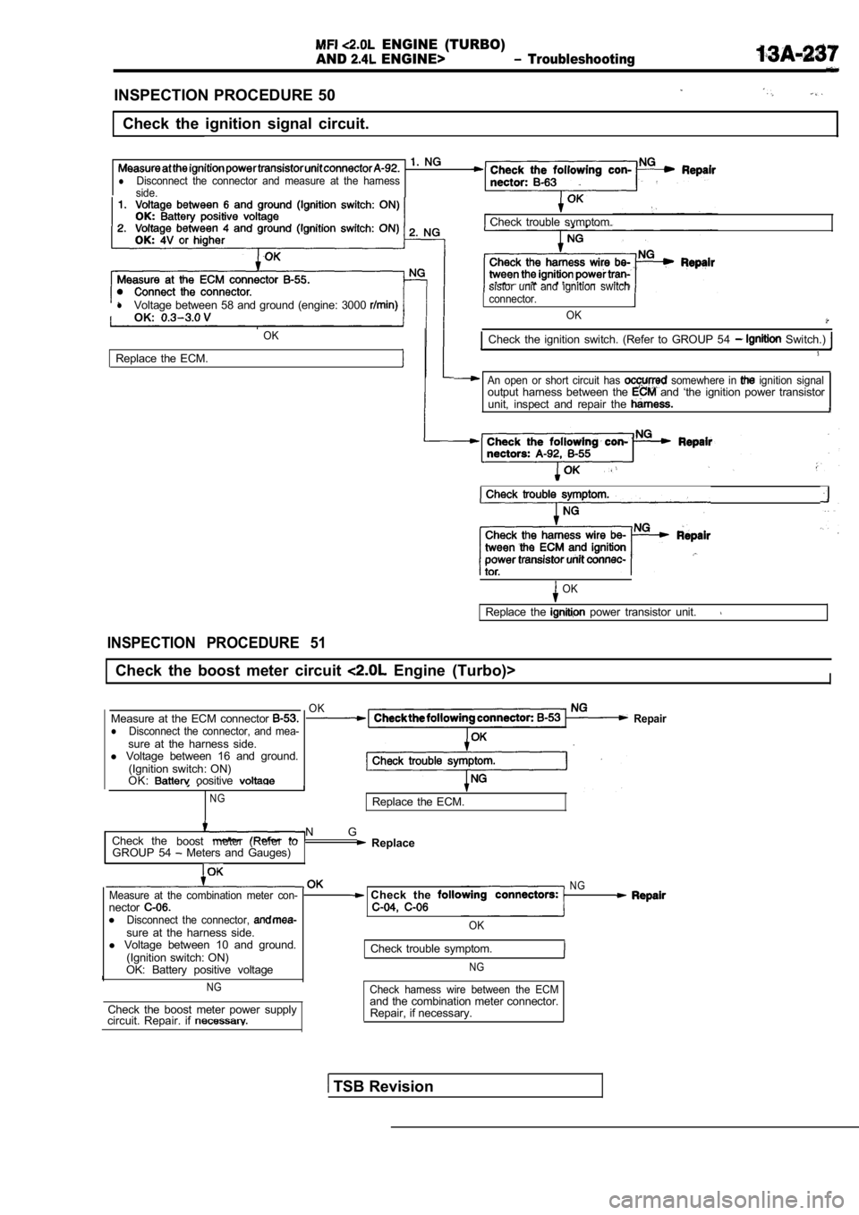
INSPECTION PROCEDURE 50
Check the ignition signal circuit.
lDisconnect the connector and measure at the harness
side.
lVoltage between 58 and ground (engine: 3000 OK:
OK
Replace the ECM. Check trouble symptom.
sistor unit and ignition switch
connector.
OK
Check the ignition switch. (Refer to GROUP 54 Switch.)
An open or short circuit has somewhere in ignition signaloutput harness between the and ‘the ignition power transistor
unit, inspect and repair the
Check trouble symptom.
OK
Replace the power transistor unit.
INSPECTION PROCEDURE 51
Check the boost meter circuit Engine (Turbo)>I
Measure at the ECM connector lDisconnect the connector, and mea-sure at the harness side.
l Voltage between 16 and ground.
(Ignition switch: ON)
OK:
oositive
NG
OKRepair
Replace the ECM.
Check the
boost meter (Refer to N G
GROUP 54 Meters and Gauges) Replace
Measure at the combination meter con-nectorlDisconnect the connector, sure at the harness side.
l Voltage between 10 and ground.
(Ignition switch: ON)
OK: Battery positive voltage
NG
Check the boost meter power supply
circuit. Repair. if
N G Check the
OK
Check trouble symptom.
NG
Check harness wire between the ECMand the combination meter connector.
Repair, if necessary.
TSB Revision
ENGINE (TURBO)
AND
ENGINE>
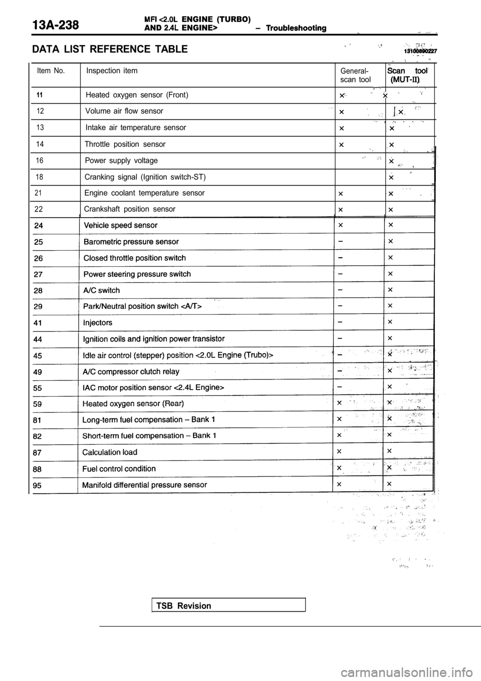
DATA LIST REFERENCE TABLE
Item No.
1 1
12
13
14
16
18
21
22
Inspection item
Heated oxygen sensor (Front)
Volume air flow sensor
Intake air temperature sensor
Throttle position sensor Power supply voltage
Cranking signal (Ignition switch-ST)
Engine coolant temperature sensor
Crankshaft position sensorGeneral-
scan tool
, . .
,
,
TSB Revision
ENGINE (TURBO)
AND ENGINE>
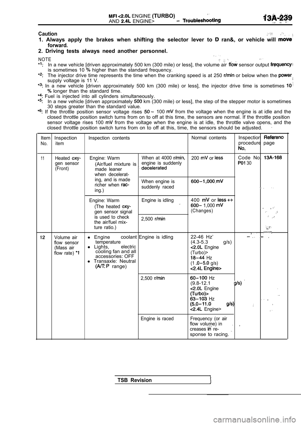
Caution
1. Always apply the brakes when shifting the select or lever to ran&, or vehicle will
forward.
2. Driving tests always need another personnel.
NOTE
In a new vehicle [driven approximately 500 km (300 mile) or less], the volume air sensor output
is sometimes 10 higher than the standard frequency.
The injector drive time represents the time when the cranking speed is at 250 or below when the
supply voltage is 11 V.
In a new vehicle [driven approximately 500 km (300 mile) or less], the injector drive time is sometimes
longer than the standard time.
Fuel is injected into all cylinders simultaneously.
In a new vehicle [driven approximately km (300 mile) or less], the step of the stepper mo tor is sometimes
30 steps greater than the standard value.
If the throttle position sensor voltage rises 100 from the voltage when the engine is at idle and th e
closed throttle position switch turns from on to of f at this time, the sensors are normal. If the throttle position
sensor voltage rises 100
from the voltage when the engine is at idle, the t hrottle valve opens, and the
closed throttle position switch turns from on to of f at this, time, the sensors should be adjusted.
Item Inspection
No.item
Inspection contents Normal contentsInspection
procedure page
11HeatedEngine: WarmWhen at 4000 200 or Code No.
gen sensor engine is suddenly(Air/fuel mixture is 30
(Front)
made leaner
when decelerat- ing, and is made
richer when
When engine is
suddenly raceding.)
Engine: Warm Engine is idling
400 or
(The heated 1,000 ,gen sensor signal(Changes)
is used to check
2,500
the air/fuel mix-
ture ratio.)
Volume airl Engine coolant Engine is idling 22-46 Hz’
flow sensortemperature(4.3-5.3 g/s)
(Mass airl
Lights,electric
flow rate) cooling fan and all Engine
accessories: OFF(Turbo)>
l Transaxle: Neutral Hz
range)(1 g/s)
2,500
Engine is raced
Hz
(9.8-12.1
Engine,
Hz ,
Engine>
Frequency (or air
flow volume) in
creases
re- ,
sponse to racing.
TSB Revision
E N G I N E .
AND ENGINE> Troubleshooting
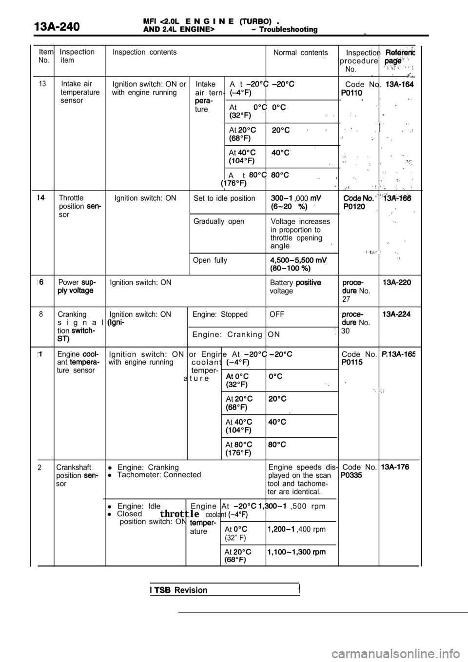
Item InspectionInspection contentsNormal contents
No. itemInspection
‘ p r o c e d u r e
No., ,
13Intake airIgnition switch: ON orIntakeA tCode No. temperaturewith engine runningair tern- sensor,
tureAt .
,
At
At
A t ,
Throttle Ignition switch: ON Set to idle position ,000 position
sor .
Gradually openVoltage increases
in proportion to
throttle opening
angle
Open fully
PowerIgnition switch: ON Battery
voltage No.
27
8
Cranking Ignition switch: ON Engine: Stopped OFF
s i g n a l No.
tionE n g i n e : C r a n k i n g O N 30
EngineIgnition switch: ON or Engine At Code No. antwith engine runningc o o l a n t
ture sensortemper-
a t u r e
At
At
At
2Crankshaftl Engine: Cranking Engine speeds dis- Code No.
positionl
Tachometer: Connectedplayed on the scan
sor tool and tachome-
ter are identical.
l Engine: Idle
l Closed Engine At , 5 0 0 r p m
throttlecoolantposition switch: ON
atureAt ,400 rpm
(32” F)
At
I Revision
