MITSUBISHI SPYDER 1990 Service Repair Manual
Manufacturer: MITSUBISHI, Model Year: 1990, Model line: SPYDER, Model: MITSUBISHI SPYDER 1990Pages: 2103, PDF Size: 68.98 MB
Page 601 of 2103
![MITSUBISHI SPYDER 1990 Service Repair Manual ENGINE (TURBO)
AND ENGINE>
INSPECTION PROCEDURE 29 ,
Fuel pump system Engine>
[Comment]l of the fuel pump The ECM judges the engine (Low, Middle, High), and outputs the result MITSUBISHI SPYDER 1990 Service Repair Manual ENGINE (TURBO)
AND ENGINE>
INSPECTION PROCEDURE 29 ,
Fuel pump system Engine>
[Comment]l of the fuel pump The ECM judges the engine (Low, Middle, High), and outputs the result](/img/19/57345/w960_57345-600.png)
ENGINE (TURBO)
AND ENGINE>
INSPECTION PROCEDURE 29 ,
Fuel pump system Engine>
[Comment]l of the fuel pump The ECM judges the engine (Low, Middle, High), and outputs the result of this judgement tol Malfunction fuel the fuel pump relay module. The fuel pump relay mod ule controls the operation of the fuel pump
in accordance with the engine which is input from the ECM. When the engine is high, Malfunction, of the fuel pump moduleImproper connector contact, open orthe fuel pump operates at high speed, and when the engine is low, the fuel pump operates
short-circuited harness at low speed.l Malfunction of the ECM,,
Check the fuel pump
OK
Measure at the fuel pump relay connector l Connect the connector.
l Voltage between 1 and ground switch: ON)
OK: Battery positive voltage Check the fuel pump drive
circuit 46.)
NG Repair lDisconnect the connector and measure at the harness
side.connector.. . 1. Voltage between 1 and ground (Ignition switch: O N)OK: Battery positive voltage2. Continuity between 5 and ground
OK: Continuity
OK
Check trouble ,
3. 2 and ground (Engine: Cranking)
4.
the terminal to the terminal 3
negative the terminal 4.
OK: Fuel pump operates.
U K
Check the following NG Repairc o n n e c t o r .
OK
Check trouble symptom
N G
Replace the fuel pump relay module
Check the harness wire between the fuel pump relay module con-nector and fuel pump relayconnector and repair if necessary.
Check the harness wire between the fuel pump relay con-nector and around and if
Check the following Repairconnector.
Check trouble
NG
Replace the ECMI
- - - Check the following Repairconnectors.
OK
Check trouble symptom.
Replace the fuel pump
TSB Revision
Page 602 of 2103
![MITSUBISHI SPYDER 1990 Service Repair Manual ENGINE (TURBO)
AND ENGINE>,
INSPECTION PROCEDURE 30
Ignition switch-ST system
[Comment]l Malfunction, of ignition switch ,
The ignition switch ST inputs a HIGH signal to the whi MITSUBISHI SPYDER 1990 Service Repair Manual ENGINE (TURBO)
AND ENGINE>,
INSPECTION PROCEDURE 30
Ignition switch-ST system
[Comment]l Malfunction, of ignition switch ,
The ignition switch ST inputs a HIGH signal to the whi](/img/19/57345/w960_57345-601.png)
ENGINE (TURBO)
AND ENGINE>,
INSPECTION PROCEDURE 30
Ignition switch-ST system
[Comment]l Malfunction, of ignition switch ,
The ignition switch ST inputs a HIGH signal to the while the engine is cranking.Improper connector
The ECM controls fuel injection, etc. during starti ng based on this input. . l t h e .
Measure at the ECM connector lDisconnect the connector, and measure at the harnes s
side.
1. Voltage between 71 and ground (Ignition switch: START)
OK: or more
2. Continuity between 91 and ground OK: Continuity
OK
R e p a i r
Check trouble symptom.
Replace the ECM. 1. NG
2. NG
. . .,
TSB Revision
Page 603 of 2103
![MITSUBISHI SPYDER 1990 Service Repair Manual ENGINE (TURBO)
AND ENGINE>
INSPECTION PROCEDURE 31Ignition switch-ST and park/neutral position
system
[Comment]
l The ignition switch ST inputs a HIGH signal to the ECM while t MITSUBISHI SPYDER 1990 Service Repair Manual ENGINE (TURBO)
AND ENGINE>
INSPECTION PROCEDURE 31Ignition switch-ST and park/neutral position
system
[Comment]
l The ignition switch ST inputs a HIGH signal to the ECM while t](/img/19/57345/w960_57345-602.png)
ENGINE (TURBO)
AND ENGINE>
INSPECTION PROCEDURE 31Ignition switch-ST and park/neutral position
system
[Comment]
l The ignition switch ST inputs a HIGH signal to the ECM while the engin e is cranking.
The ECM controls fuel injection, etc. during starti ng based on this input.
l The park/neutral position switch inputs the conditi on of the select lever, i.e. whether it is
in
or range or in some other range, to the The ECM controls the idle air control motor based o n this input.l
Malfunction of
switch park/neutral switchImproper connector contact, open circuit or
shortcircuited harness wire
l Malfunction of the
I , .
,
.Check the park/neutral position switch. (Refer to G ROUP Replace On-vehicle Service.)
park/neutral position switchand ignition switch connector.
OK
Check the ignition switch. (Refer to GROUP 54 Switch.)
1. NG
Measure at the position switch connector
lDisconnect the connector, and measure at the harnes s2. NGOKside.Voltage between 8 and ground Engine (Turbo)>(Ignition switch: ON) Check trouble symptom.ING . ,
Voltage between 5 and ground Engine>(Ignition switch: ON) NGOK: Battery positive voltage 3. NGCheck harness wire between
2. Continuity between 7 and ground ECM and park/neutral Engine (Turbo)>tion switch connector.
Continuity between 8 and ground Engine>OK
OK: Continuity3.Voltage between 8 and ground Engine Replace the ECM.
Voltage between 5 and ground
l Ignition switch: START
l Disconnect ECM connector.Check harness wire between park/neutral OK: Battery positive voltage and starter terminal. Repair, if necessary.
OK, ,
TSB Revision
Page 604 of 2103
![MITSUBISHI SPYDER 1990 Service Repair Manual E N G I N E
AND ‘ENGINE> Troubleshooting
INSPECTION PROCEDURE 32
switch and compressor clutch relay system, . .
(Comment]l Malfunction of control When an A/C ON signal is i MITSUBISHI SPYDER 1990 Service Repair Manual E N G I N E
AND ‘ENGINE> Troubleshooting
INSPECTION PROCEDURE 32
switch and compressor clutch relay system, . .
(Comment]l Malfunction of control When an A/C ON signal is i](/img/19/57345/w960_57345-603.png)
E N G I N E
AND ‘ENGINE> Troubleshooting
INSPECTION PROCEDURE 32
switch and compressor clutch relay system, . .
(Comment]l Malfunction of control When an A/C ON signal is input to the the ECM carries out control of the idle air control Malfunction of motor, and also operates the compressor magnetic clutch.lImproper connector open circuit or harness .
NG
(Refer toGROUP55 On-vehicleService.) Replace
OK
Measure at the ECM connectors lDisconnect the connector, and measure at the harness
lVoltage between 22 and ground, and 45 and ground
(Ignition switch: ON)
(A/C switch: ON)
OK: Battery positive voltage
l Shortcircuit between 22 and ground
(Ignition switch: ON)
switch: ON)
OK: compressor clutch turns ON.
OK
N G
OK
Check trouble symptom.
the
NG
TSB RevisionI
Page 605 of 2103
![MITSUBISHI SPYDER 1990 Service Repair Manual ENGINE (TURBO)
AND
INSPECTION PROCEDURE 33
Fan motor relay system (Radiator fan, A/C condenser fan)Probable cause
[Comment]l Malfunction of fan motor relay
The fan motor relay is MITSUBISHI SPYDER 1990 Service Repair Manual ENGINE (TURBO)
AND
INSPECTION PROCEDURE 33
Fan motor relay system (Radiator fan, A/C condenser fan)Probable cause
[Comment]l Malfunction of fan motor relay
The fan motor relay is](/img/19/57345/w960_57345-604.png)
ENGINE (TURBO)
AND
INSPECTION PROCEDURE 33
Fan motor relay system (Radiator fan, A/C condenser fan)Probable cause
[Comment]l Malfunction of fan motor relay
The fan motor relay is controlled by the power tran sistor inside the ECM turning ON and OFF.l Malfunction of fan motorImproper connector open shortclrcuitedl Malfunction of the ECM
Disconnect the connector, and measure at the harnes s
Voltage between 20 and ground, and 21 and ground
l Shortcircuit between 20 and ground (Ignition switch :
Check the Repair
O K
Check trouble symptom.
OK: Radiator fan and condenser fan rotate at highspeed.l Shortcircuit between 21 and ground (Ignition switch :
OK: Radiator fan and condenser fan rotate at lowspeed.
l Check the radiator fan circuit
l Check the condenser fan circuit.
TSB RevisionI
Page 606 of 2103
![MITSUBISHI SPYDER 1990 Service Repair Manual ENGINE (TURBO)AND Troubleshooting
INSPECTION PROCEDURE 34
Ignition circuit system cause’
[Comment]l Malfunction of ignition The interrupts the ignition coil current by turning the MITSUBISHI SPYDER 1990 Service Repair Manual ENGINE (TURBO)AND Troubleshooting
INSPECTION PROCEDURE 34
Ignition circuit system cause’
[Comment]l Malfunction of ignition The interrupts the ignition coil current by turning the](/img/19/57345/w960_57345-605.png)
ENGINE (TURBO)AND Troubleshooting
INSPECTION PROCEDURE 34
Ignition circuit system cause’
[Comment]l Malfunction of ignition The interrupts the ignition coil current by turning the transistor in- of side the ECM ON and OFF.l Improper connector contact, open circuit or,
shortcircuited harness wire
l Malfunction
the ECM
Engine (Turbo)>
Measure at the ignition coil connector
lDisconnect the connector and measure at the harness
side.
l Voltage between 3 and ground (Ignition switch: ON)
OK: Battery positive voltage
Engine>
Measure at the ignition coil connectors 0, lDisconnect the connectors and measure at the harnes s
side.
l Voltage between 1 and ground (Ignition switch: ON)
OK: Battery positive voltage
OK
lDisconnect the connector, and measure at the harnes s
side.
l Continuity between 3 and ground
OK: Continuitv
Check trouble symptom.
Check the ignition switch. (Refer to Ignition Switch.)
N GCheck the harness wire between ignition connectorand ground. Repair, if necessary.
OK
Check the following connectors: EngineNG Repair(Turbo)>, Engine>, A-l 11
OK
Check trouble symptom.
NG Replace
(Refer toGROUP16 Ignition System.)
Check the ignition power tranNG Replace
(Refer to GROUP 16 Ignition
OK
lDisconnect the connector, and measure at the harnes s
side.
1. Voltage between each of 1, and ground
(Ignition switch: ON)
OK: Battery positive voltage
2.
between each of 2. 7 and around Cranking)
OK:
Check the following con- NG Repair
I
Check trouble symptom.
NGI
Check the harness wire between the ignition coil an d ignition power
transistor unit connector. Repair, if necessary.
.
Check trouble symptom.
Check trouble symptom.
NG
Check the ignition signal circuit. (Refer to INSPECTION PROCEDURE
Replace the ECM.
TSB Revision
Page 607 of 2103
![MITSUBISHI SPYDER 1990 Service Repair Manual ENGINE (TURBO)
AND
ENGINE> Troubleshooting
INSPECTION PROCEDURE 35
Idle air control motor (DC motor) Engine>P r o b a b l e c a u s e
[Comment]l Malfunction of idle air control mo MITSUBISHI SPYDER 1990 Service Repair Manual ENGINE (TURBO)
AND
ENGINE> Troubleshooting
INSPECTION PROCEDURE 35
Idle air control motor (DC motor) Engine>P r o b a b l e c a u s e
[Comment]l Malfunction of idle air control mo](/img/19/57345/w960_57345-606.png)
ENGINE (TURBO)
AND
ENGINE> Troubleshooting
INSPECTION PROCEDURE 35
Idle air control motor (DC motor) Engine>P r o b a b l e c a u s e
[Comment]l Malfunction of idle air control motor
The ECM controls the intake air volume during idlin g by opening and closing the I m p r o p e r c o n n e c t o r open “circuit’ servo valve located in the bypass passage.
l Malfunction of the
at the idle air control motor connector Connect the connector. (Use test harness: Voltage between 5 and ground (Ignition switch: ON)
OK: 2 or more to 0 (momentarily) Voltage between 6 and ground (Ignition switch: ON)OK: 4 or more to 0 (momentarily)
OK
the idle air control motor.1
Check symptom.
Replace
INSPECTION PROCEDURE 36
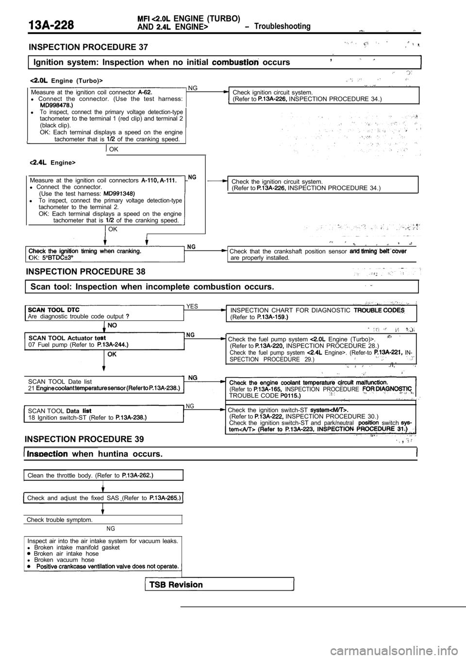
Scan tool: Inspection when no initial combustion oc curs
SCAN TOOL Data listNGCheck the power and ignition 16 Voltage of ECM power source (Refer to (Refer to I PROCEDURE 27.)
(Whenoil filler cap is removed.)
SCAN TOOL DTC
Are the diagnostic trouble codes output
Check timing belt for breakage.
INSPECTION CHART FOR TROUBLE CODES.
(Refer to
SCAN TOOL list NG
22 Crankshaft position sensor OK: Cranking speed is displayed.
OK
Check the crankshaft position sensor circuit malfu nction. (Refer to INSPECTION PROCEDURE FOR DIAGNOSTIC
TROUBLE CODES
SCAN TOOL Actuator testCheck the fuel pump system Engine 07 Fuel pump (Refer to (Refer to INSPECTION PROCEDURE 28.)
OKCheck the fuel pump system (Refer to INSPECTION PROCEDURE 29) .
SCAN TOOL list21 Check the engine coolant temperature circuit (Refer to INSPECTION PROCEDURE FOR DIAGNOSTICTROUBLE CODES
TSB Revision
Page 608 of 2103

ENGINE (TURBO)
AND ENGINE> Troubleshooting
INSPECTION PROCEDURE 37 ,
Ignition system: Inspection when no initial occurs,
Engine (Turbo)> NGMeasure at the ignition coil connector Check ignition circuit system.
l Connect the connector. (Use the test harness:
(Refer to INSPECTION PROCEDURE 34.)
lTo inspect, connect the primary voltage detection-typetachometer to the terminal 1 (red clip) and terminal 2
(black clip).
OK: Each terminal displays a speed on the engine tachometer that is
of the cranking speed.
OK
Engine>
Measure at the ignition coil connectors
l Connect the connector.
(Use the test harness:
lTo inspect, connect the primary voltage detection-t ypetachometer to the terminal 2.OK: Each terminal displays a speed on the engine
tachometer that is of the cranking speed.
OK
NGCheck the ignition circuit system.(Refer to INSPECTION PROCEDURE 34.)
OK:
NG Check that the crankshaft position sensor are properly installed.
INSPECTION PROCEDURE 38
Scan tool: Inspection when incomplete combustion oc curs.
YESINSPECTION CHART FOR DIAGNOSTIC Arediagnostic trouble code output (Refer to
SCAN TOOL Actuator te
07 Fuel pump (Refer toNG, Check the fuel pump system Engine (Turbo)>.(Refer to INSPECTION PROCEDURE 28.)Check the fuel pump system Engine>. (Refer-to IN-
SPECTION PROCEDURE 29.)
./I,’
SCAN TOOL Date list21(Refer to INSPECTION PROCEDURE TROUBLE CODE
NGSCAN TOOL Data Check the ignition switch-ST 18 Ignition switch-ST (Refer to (Refer to INSPECTION PROCEDURE 30.)
Check the ignition switch-ST andpark/neutralswitch
INSPECTION PROCEDURE 39 ,
when huntina occurs.
Clean the throttle body. (Refer to
I
Check and adiust the fixed SAS (Refer to
Check trouble symptom.
NG
Inspect air into the air intake system for vacuum l eaks.
l Broken intake manifold gasket
Broken air intake hose
l Broken vacuum hose
Page 609 of 2103

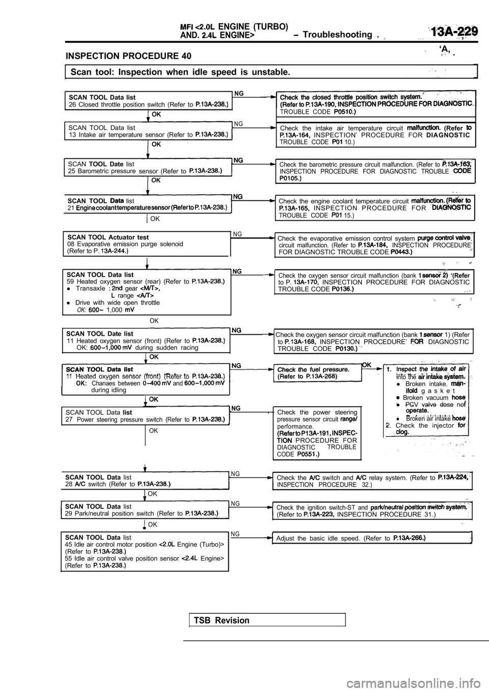
ENGINE (TURBO)
AND. ENGINE> Troubleshooting . ,
INSPECTION PROCEDURE 40
‘A, .
Scan tool: Inspection when idle speed is unstable.
SCAN TOOL Data list
NG
26 Closed throttle position switch (Refer to TROUBLE CODE
SCAN TOOL Data listNG Check the intake air temperature circuit (Refer 13 Intake air temperature sensor (Refer to INSPECTION’ PROCEDURE FOR DIAGNOSTICTROUBLE CODE 10.)
SCANTOOL Date listCheck the barometric pressure circuit malfunction. (Refer to 25 Barometric pressure
sensor (Refer toINSPECTION PROCEDURE FOR DIAGNOSTIC TROUBLE
.
SCAN TOOL list Check the engine coolant temperature circuit 21 I N S P E C T I O N P R O C E D U R E F O R
OKTROUBLE CODE 15.)
SCAN TOOL Actuator test
08 Evaporative emission purge solenoid
(Refer to P. NG Check the evaporative emission control system circuit malfunction. (Refer to INSPECTION PROCEDURE’FOR DIAGNOSTIC TROUBLE CODE
SCAN TOOL Data listNG
59 Heated oxygen sensor (rear) (Refer to l Transaxle gear range l Drive with wide open throttleOK: 1,000
OK
SCAN TOOL Date list11 Heated oxygen sensor (front) (Refer to OK: during sudden racing
Check the oxygen sensor circuit malfunction (bank ‘(Referto P. INSPECTION PROCEDURE FOR DIAGNOSTIC
TROUBLE CODE
Check the oxygen sensor circuit malfunction (bank 1) (Refer
to INSPECTION PROCEDURE’ DIAGNOSTIC
TROUBLE CODE
11Heated oxygen sensor (front) (Refer toOK:Chanaes between and during idlingI
SCAN TOOL Data listNG.
27
Power steering pressure switch (Refer to
OK
Check the power steeringpressure sensor circuit performance.
PROCEDURE FORDIAGNOSTIC TROUBLE
CODE
into the l Broken intake. g a s k e t Broken vacuum l PCV valve dose not
lBroken air intake 2. Check the injector
SCAN TOOL Data list
28 switch (Refer to
OK
N GCheck the switch and relay system. (Refer to INSPECTION PROCEDURE 32.)
SCAN TOOL Data listN G
29 Park/neutral position switch (Refer to Check the ignition switch-ST and (Refer to INSPECTION PROCEDURE 31.)
OK
SCAN TOOL Data list
45 Idle air control motor position Engine (Turbo)>
(Refer to
55 Idle air control valve position sensor Engine>
(Refer to
NGAdjust the basic idle speed. (Refer to
TSB Revision
Page 610 of 2103
