MITSUBISHI SPYDER 1990 Service Repair Manual
Manufacturer: MITSUBISHI, Model Year: 1990, Model line: SPYDER, Model: MITSUBISHI SPYDER 1990Pages: 2103, PDF Size: 68.98 MB
Page 631 of 2103
ENGINE (TURBO)
AND ENGINE>
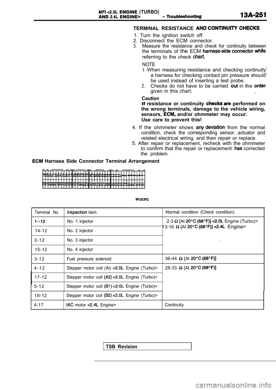
TERMINAL RESISTANCE
1. Turn the ignition switch off.
2. Disconnect the ECM connector.
3.Measure the resistance and check for continuity bet ween
the terminals of theECM
referring to the check
NOTE
1.When measuring resistance and checking continuity’
a harness for checking contact pin pressure should’
be used instead of inserting a test probe.
2.Checks do not have to be carried in the
given in this chart.,
Caution
If resistance or continuity performed on
the wrong terminals, damage to the vehicle wiring,
sensors,
and/or ohmmeter may occur.
Use care to prevent this!
4. If the ohmmeter shows
from the normal
condition, check the corresponding sensor, actuator and
related electrical wiring, and then repair or replace.
5. After repair or replacement, recheck with the oh mmeter
to confirm that the repair or replacement
corrected
the problem.
Harness Side Connector Terminal Arrangement
Terminal No. item Normal condition (Check condition)
No. 1 injector2-3 [At Engine (Turbo)>
No. 2 injector13-16 [At Engine>
14-12
2 - 1 2
No. 3 injector
15-12No. 4 injector
3 - 1 2Fuel pressure solenoid36-44 [At
4 - 1 2Stepper motor coil (Al) Engine (Turbo)>28-33 [At
17-12Stepper motor coil Engine (Turbo)>
5 - 1 2Stepper motor coil Engine (Turbo)>
18-12Stepper motor coil Engine (Turbo)>
4-17 motor Engine> Continuity
TSB Revision
Page 632 of 2103
ENGINE (TURBO)
AND ENGINE> Troubleshooting
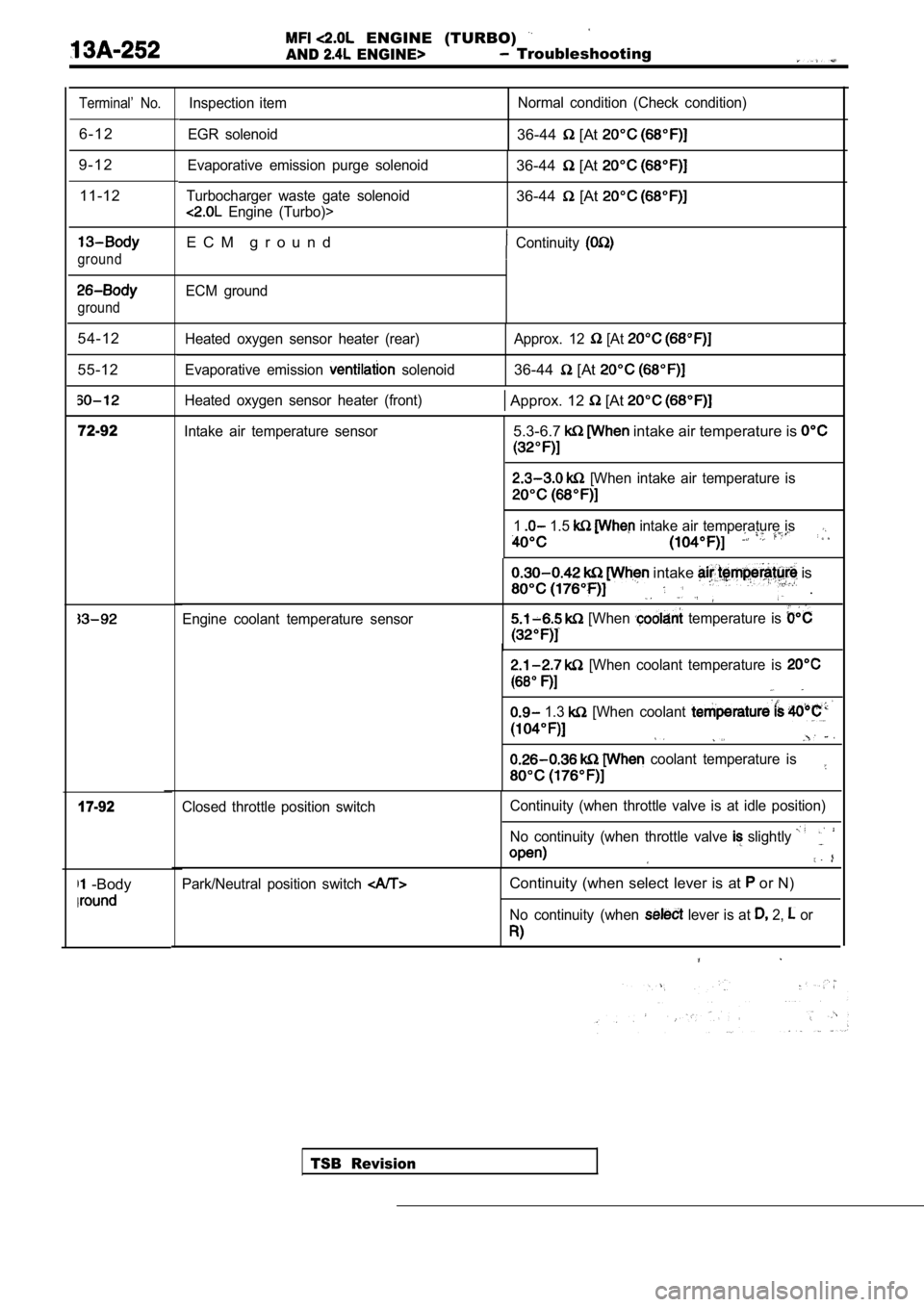
Terminal’ No.
6 - 1 2
9 - 1 2 11-12
ground
ground
54-12
55-12
72-92
17-92
-Body
Inspection item
EGR solenoid Normal condition (Check condition)
36-44 [At
Evaporative emission purge solenoid
Turbocharger waste gate solenoid
Engine (Turbo)>
36-44 [At
36-44 [At
E C M g r o u n dContinuity
ECM ground
Heated oxygen sensor heater (rear)
Evaporative emission
solenoid Approx. 12
[At
36-44 [At
Heated oxygen sensor heater (front) Approx. 12 [At
Intake air temperature sensor5.3-6.7 intake air temperature is
[When intake air temperature is
1 1.5 intake air temperature is
Engine coolant temperature sensor
intake is
.
[When temperature is
[When coolant temperature is
1.3 [When coolant
coolant temperature is
TSB Revision
Closed throttle position switch
Continuity (when throttle valve is at idle position
)
No continuity (when throttle valve
slightly
Park/Neutral position switch Continuity (when select lever is at or N)
No continuity (when lever is at 2, or
Page 633 of 2103
ENGINE (TURBO)
AND
ENGINE> Troubleshooting
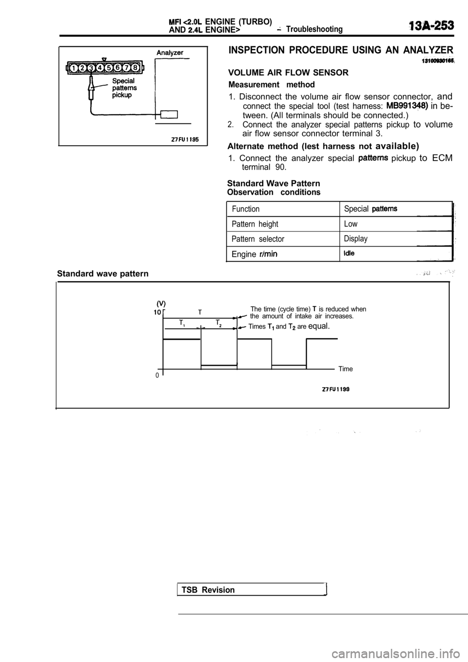
INSPECTION PROCEDURE USING AN ANALYZER
VOLUME AIR FLOW SENSOR
Measurement method
1. Disconnect the volume air flow sensor connector, and
connect the special tool (test harness: in be-
tween. (All terminals should be connected.)
2.Connect the analyzer special patterns pickup to volume
air flow sensor connector terminal 3.
Alternate method (lest harness not available)
1. Connect the analyzer special
pickup to ECM
terminal 90.
Standard Wave Pattern
Observation conditions
FunctionSpecial
Pattern height Low
Pattern selector Display
Engine
Standard wave pattern
The time (cycle time) is reduced when the amount of intake air increases.
Times and are equal.
0Time
TSB Revision
Page 634 of 2103
ENGINE (TURBO)
AND ENGINE> Troubleshooting . .
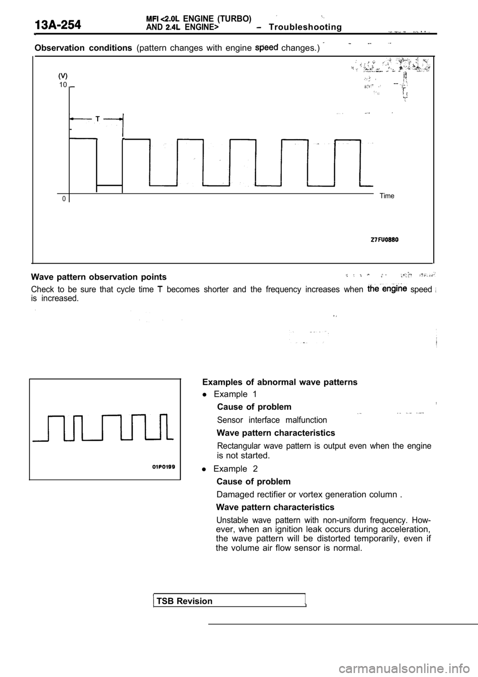
Observation conditions (pattern changes with engine changes.)
.
id
10--
0Time
Wave pattern observation points
Check to be sure that cycle time becomes shorter and the frequency increases when speed
is increased.
TSB Revision1
Examples of abnormal wave patterns
l Example 1
,Cause of problem
Sensor interface malfunction
Wave pattern characteristics
Rectangular wave pattern is output even when the en gine
is not started.
l Example 2
Cause of problem
Damaged rectifier or vortex generation column .
Wave pattern characteristics
Unstable wave pattern with non-uniform frequency. H ow-
ever, when an ignition leak occurs during acceleration,
the wave pattern will be distorted temporarily, eve n if
the volume air flow sensor is normal.
Page 635 of 2103
ENGINE (TURBO)
AND ENGINE>
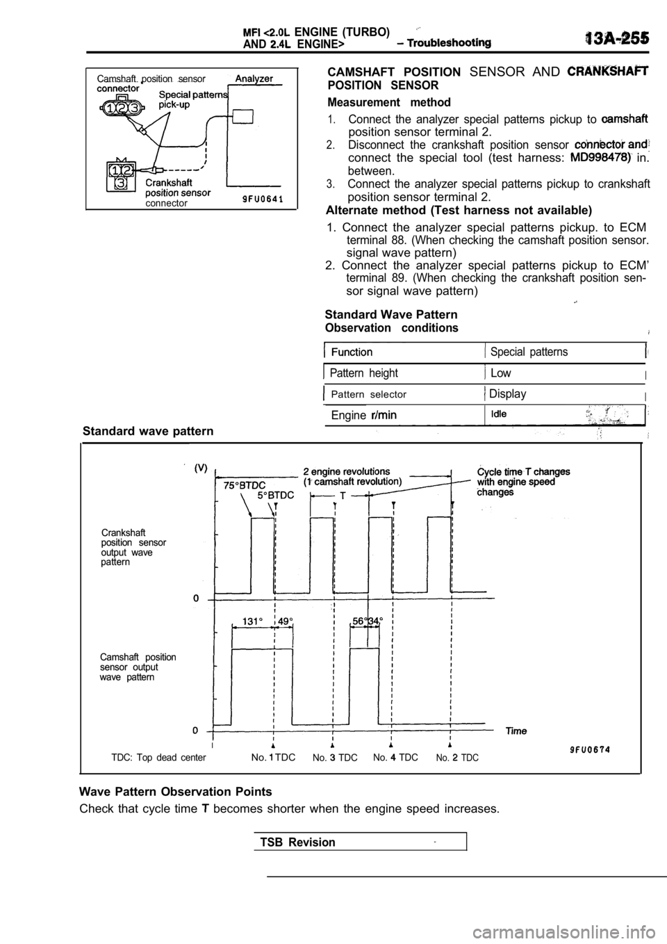
CAMSHAFT POSITION SENSOR AND
POSITION SENSOR
Measurement method
1.Connect the analyzer special patterns pickup to
position sensor terminal 2.
2.Disconnect the crankshaft position sensor
connect the special tool (test harness: in.
between.
3.Connect the analyzer special patterns pickup to cra nkshaft
position sensor terminal 2.
Alternate method (Test harness not available)
1. Connect the analyzer special patterns pickup. to ECM
terminal 88. (When checking the camshaft position sensor.
signal wave pattern)
2. Connect the analyzer special patterns pickup to ECM’
terminal 89. (When checking the crankshaft position sen-
sor signal wave pattern)
Standard Wave Pattern
Observation conditions
Camshaft position sensor
connector
Standard wave pattern
Crankshaft
Crankshaft
position sensor
position sensor
output wave
output wave
pattern
pattern
Camshaft position
Camshaft position
sensor output
sensor output
wave pattern
wave pattern
Special patterns
Pattern height LowI
Pattern selector DisplayI
Engine
I
TDC: Top dead centerNo. TDCNo. TDC No. TDCNo. TDC
Wave Pattern Observation Points
Check that cycle time
becomes shorter when the engine speed increases.
TSB Revision
Page 636 of 2103
ENGINE (TURBO)
AND
ENGINE> Troubleshooting
Analyzer
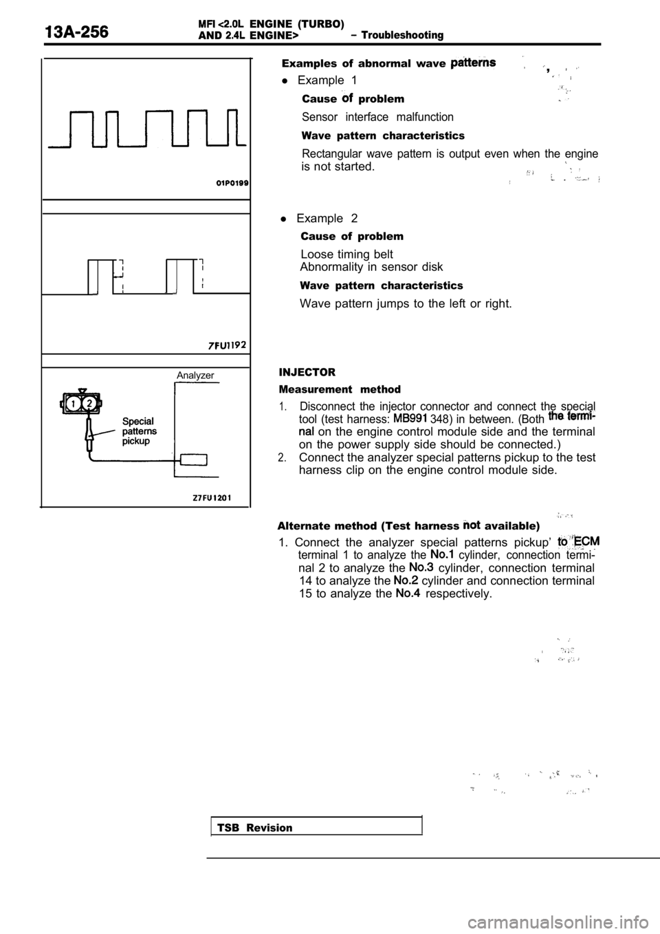
Examples of abnormal wave ,
l Example 1
Cause problem
Sensor interface malfunction
Wave pattern characteristics
Rectangular wave pattern is output even when the en gine
is not started.
l Example 2
Cause of problem
Loose timing belt
Abnormality in sensor disk
Wave pattern characteristics
Wave pattern jumps to the left or right.
INJECTOR
Measurement method
1.Disconnect the injector connector and connect the s pecial
tool (test harness:
348) in between. (Both
on the engine control module side and the terminal
on the power supply side should be connected.)
2.Connect the analyzer special patterns pickup to the test
harness clip on the engine control module side.
Alternate method (Test harness available)
1. Connect the analyzer special patterns pickup’
terminal 1 to analyze the cylinder, connection termi-
nal 2 to analyze the cylinder, connection terminal
14 to analyze the
cylinder and connection terminal
15 to analyze the
respectively.
TSB Revision
Page 637 of 2103
ENGINE (TURBO)
AND ENGINE> Troubleshooting
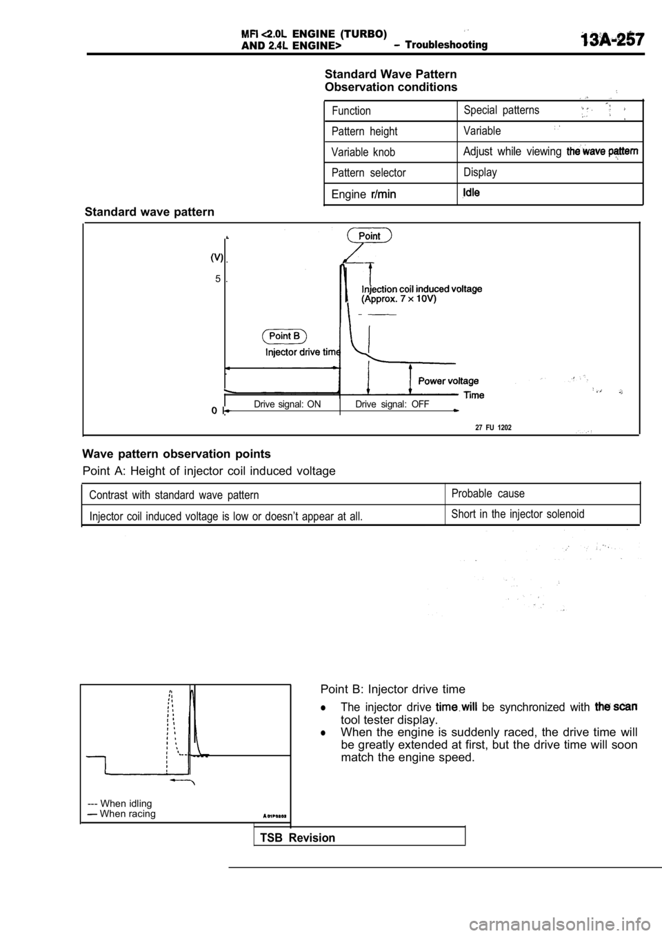
Standard Wave Pattern
Observation conditions
FunctionSpecial patterns
Pattern height
Variable
Standard wave pattern
Variable knobAdjust while viewing
Pattern selector Display
Engine
.
5 .
Drive signal: ON Drive signal: OFF
27 FU 1202
Wave pattern observation points Point A: Height of injector coil induced voltage
Contrast with standard wave pattern
Injector coil induced voltage is low or doesn’t app ear at all.Probable cause
Short in the injector solenoid
TSB Revision
--- When idling When racing
Point B: Injector drive time
lThe injector drive be synchronized with
tool tester display.
lWhen the engine is suddenly raced, the drive time w ill
be greatly extended at first, but the drive time wi ll soon
match the engine speed.
Page 638 of 2103
Analyzer
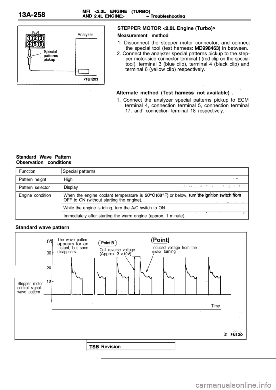
STEPPER MOTOR Engine (Turbo)>
Measurement method
1. Disconnect the stepper motor connector, and connect
the special tool (test harness:
in between.
2. Connect the analyzer special patterns pickup to the step-
per motor-side connector terminal (red clip on the special
tool), terminal 3 (blue clip), terminal 4 (black clip) and
terminal 6 (yellow clip) respectively.
Alternate method (Test
not available) .
1. Connect the analyzer special patterns pickup to ECM
terminal 4, connection terminal 5, connection termi nal
17, and’ connection terminal 18 respectively.
Standard Wave Pattern
Observation conditions
Function Special patterns
Pattern height
Pattern selector
Engine conditionHigh
Display
When the engine coolant temperature is or below,
OFF to ON (without starting the engine)..
While the engine is idling, turn the A/C switch to ON.. .Immediately after starting the warm engine (approx. 1 minute).
Standard wave pattern
The wave patternappears for aninstant, but soon
30disappears.
Stepper motor
10
control signal
wave pattern
Coil reverse voltage(Approx. 3
(Point]
induced voltage from the turning
Time
Revision
Page 639 of 2103
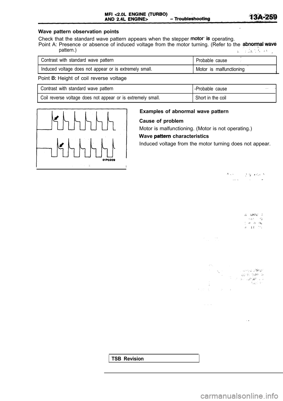
Wave pattern observation pointsCheck that the standard wave pattern appears when t he stepper
operating.
Point A: Presence or absence of induced voltage fro m the motor turning. (Refer to the
pattern.)
Contrast with standard wave pattern
Probable cause
Induced voltage does not appear or is extremely small.Motor is malfunctioning
Point Height of coil reverse voltage
Contrast with standard wave pattern
-Probable cause
Coil reverse voltage does not appear or is extremely small.
Short in the coil
Examples of abnormal wave pattern
Cause of problem
Motor is malfunctioning. (Motor is not operating.)
Wave
characteristics
Induced voltage from the motor turning does not app ear.
I
.
TSB Revision
Page 640 of 2103
ENGINE (TURBO)
AND ENGINE>
Analyzer
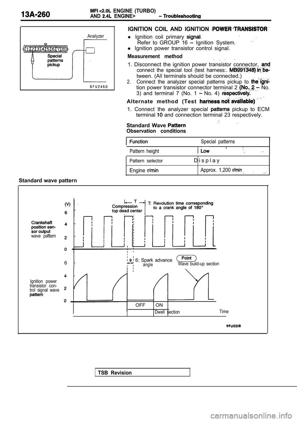
IGNITION COIL AND IGNITION
l Ignition coil primary
Refer to GROUP 16 Ignition System.
l Ignition power transistor control signal.
Measurement method
1. Disconnect the ignition power transistor connect or,
connect the special tool (test harness:.
tween. (All terminals should be connected.)
2.Connect the analyzer special patterns pickup to
tion power transistor connector terminal 2 No.
3) and terminal 7 (No. 1
No. 4)
A l t e r n a t e m e t h o d ( T e s t
1. Connect the analyzer special pickup to ECM
terminal
and connection terminal 23 respectively.
Standard Wave
Observation conditions
Special patterns
Pattern height
Pattern selector
Engine
D i s p l a y
Approx. 1,200
Standard wave pattern
TSB Revision
wave pattern
6 6: Spark advanceangleWave build-up section
Ignition power
transistor con-
trol signal wave
OFF ON
Dwell section Time