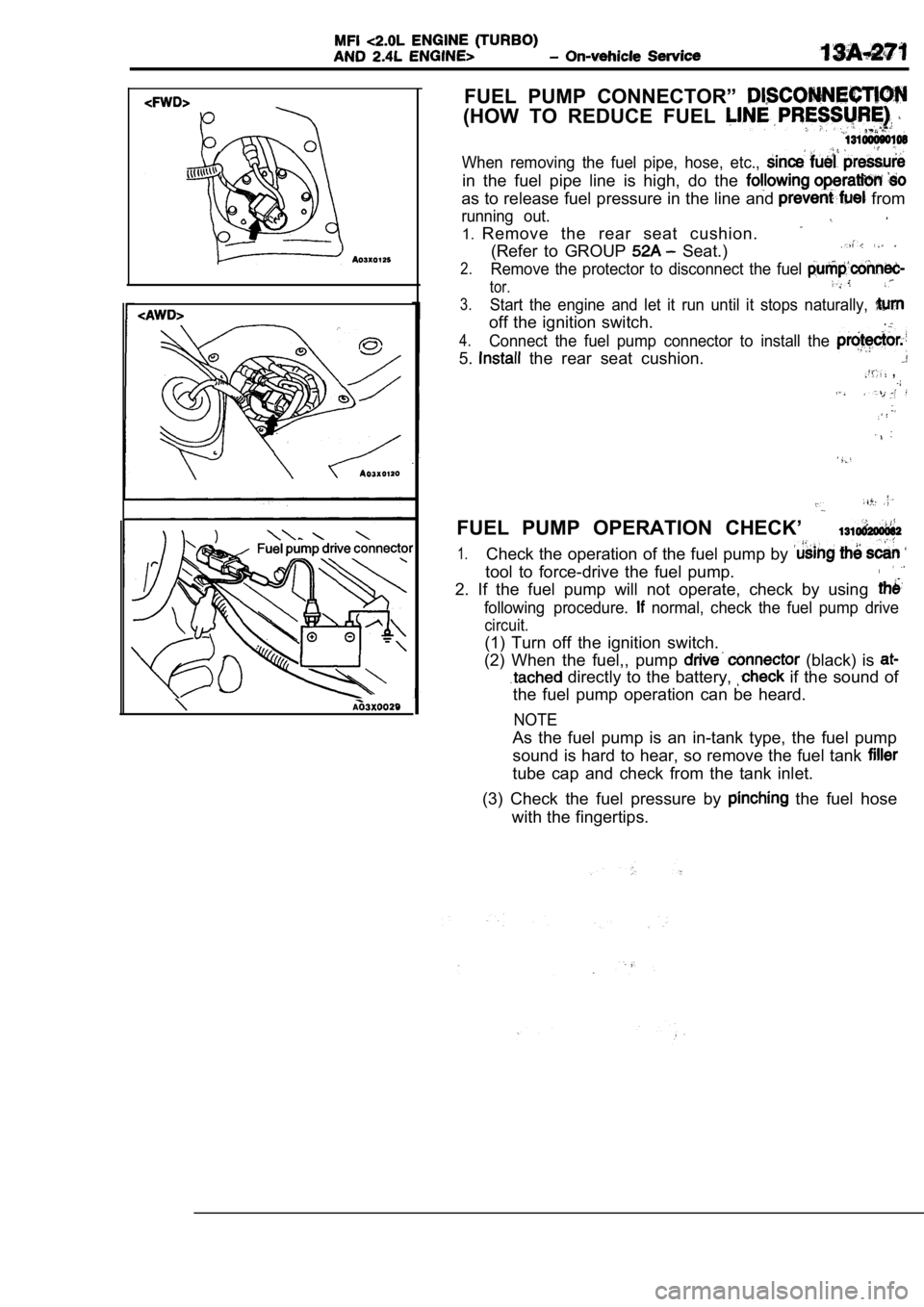
FUEL PUMP CONNECTOR”
(HOW TO REDUCE FUEL
When removing the fuel pipe, hose, etc.,
in the fuel pipe line is high, do the
as to release fuel pressure in the line and from
running out.
1.Remove the rear seat cushion.
(Refer to GROUP Seat.)
2.Remove the protector to disconnect the fuel
tor.
3.Start the engine and let it run until it stops natu rally,
off the ignition switch..
4.Connect the fuel pump connector to install the
5. the rear seat cushion. ,
FUEL PUMP OPERATION CHECK’
1.Check the operation of the fuel pump by
tool to force-drive the fuel pump.
2. If the fuel pump will not operate, check by usin g
following procedure. normal, check the fuel pump drive
circuit.
(1) Turn off the ignition switch.
(2) When the fuel,, pump
(black) is
directly to the battery, if the sound of
the fuel pump operation can be heard.
NOTE
As the fuel pump is an in-tank type, the fuel pump
sound is hard to hear, so remove the fuel tank
tube cap and check from the tank inlet.
(3) Check the fuel pressure by
the fuel hose
with the fingertips.
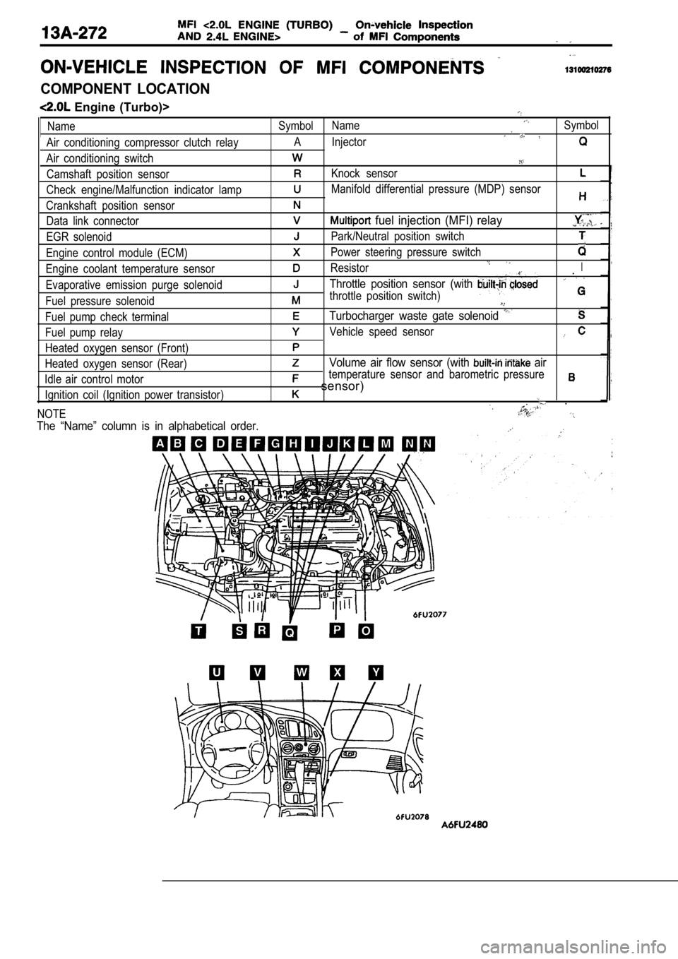
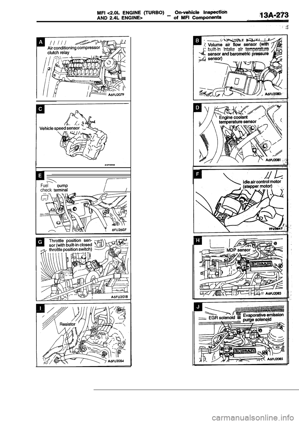
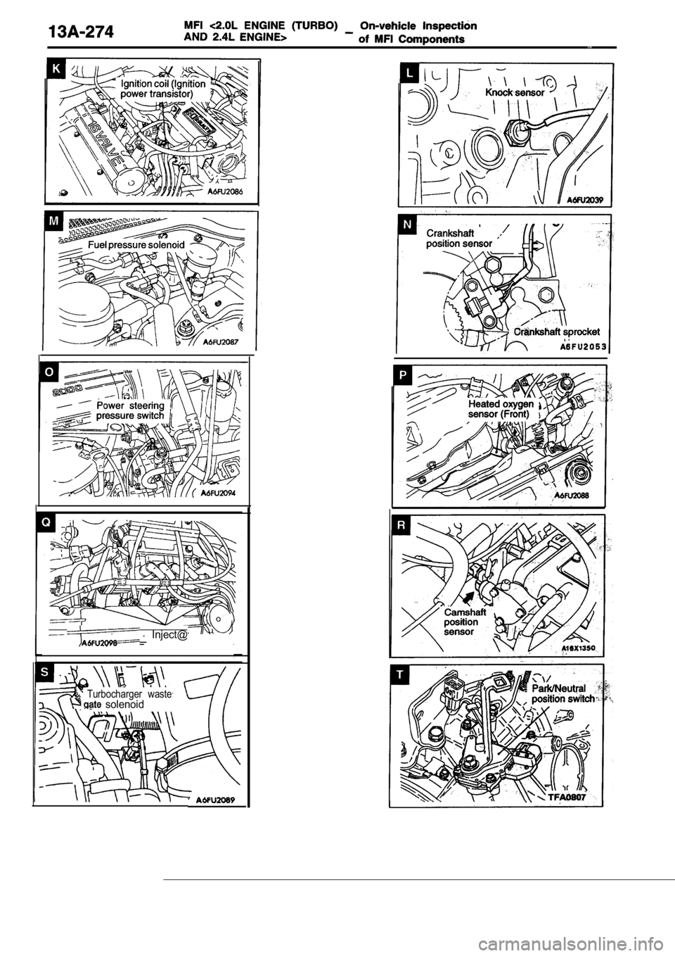
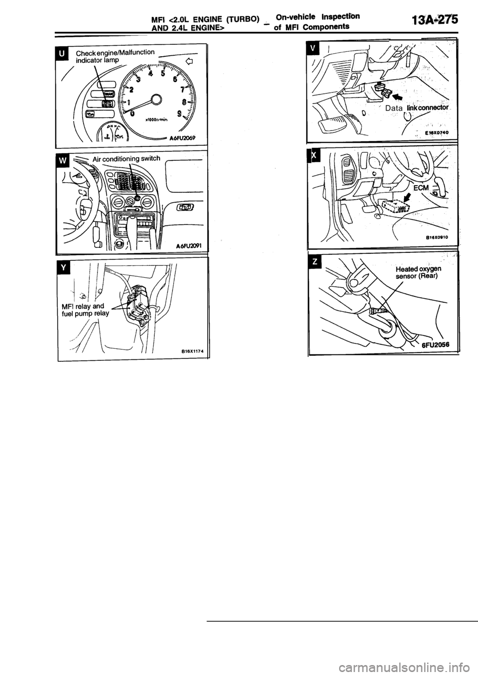
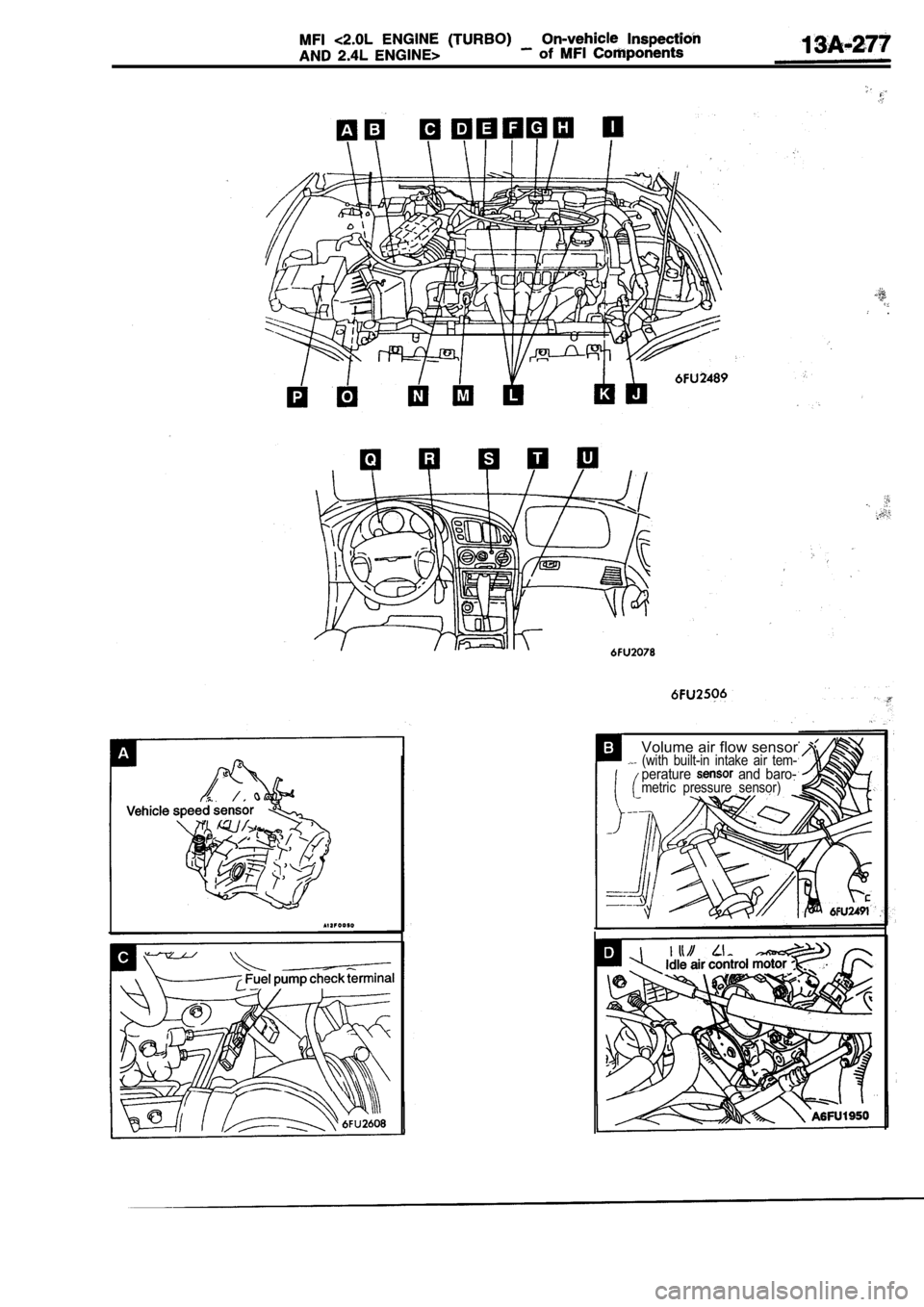
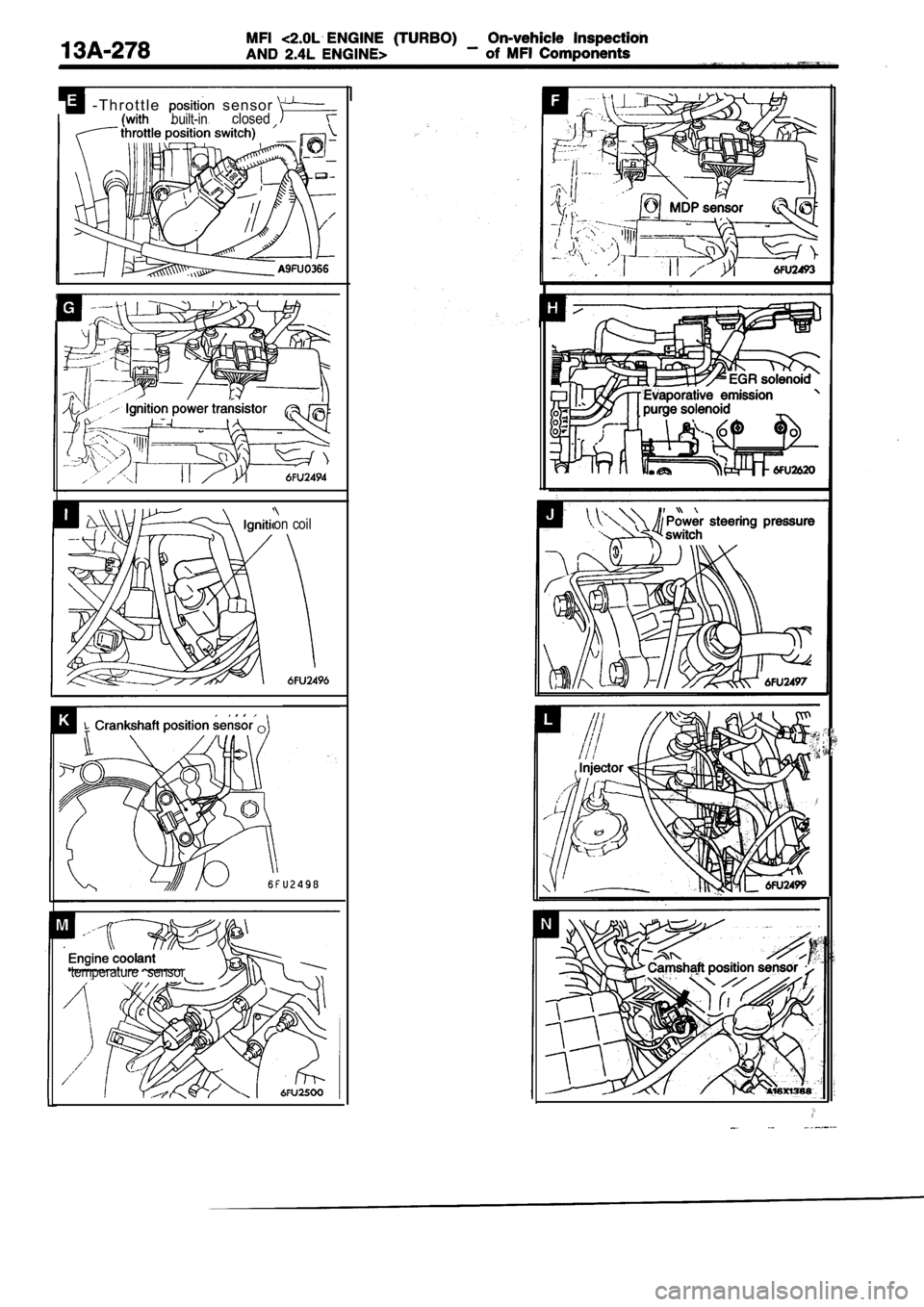
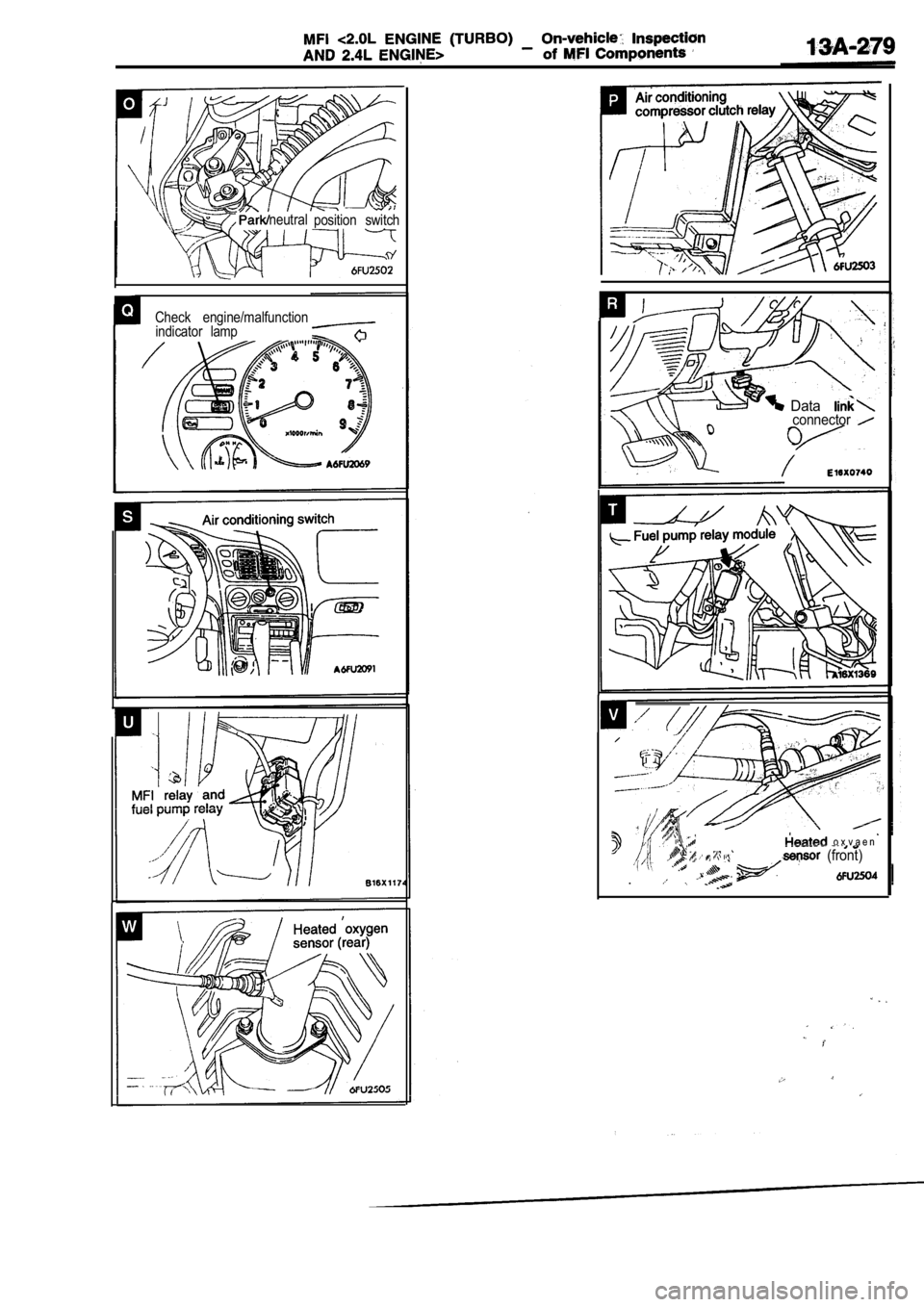
COMPONENT LOCATION
Engine (Turbo)>
Name
Air conditioning compressor clutch relay
Air conditioning switch Camshaft position sensor
Check engine/Malfunction indicator lamp
Crankshaft position sensor Data link connector
EGR solenoid
Engine control module (ECM)
Engine coolant temperature sensor
Evaporative emission purge solenoid
Fuel pressure solenoid
Fuel pump check terminal
Fuel pump relay
Heated oxygen sensor (Front)
Heated oxygen sensor (Rear)
Idle air control motor Ignition coil (Ignition power transistor)
NOTESymbol NameSymbol
A Injector
Knock sensor
Manifold differential pressure (MDP) sensor
fuel injection (MFI) relay
Park/Neutral position switch
Power steering pressure switch
ResistorI.
Throttle position sensor (with
throttle position switch)
Turbocharger waste gate solenoid
Vehicle speed sensor
Volume air flow sensor (with air
temperature sensor and barometric pressure
sensor)
.
The “Name” column is in alphabetical order.
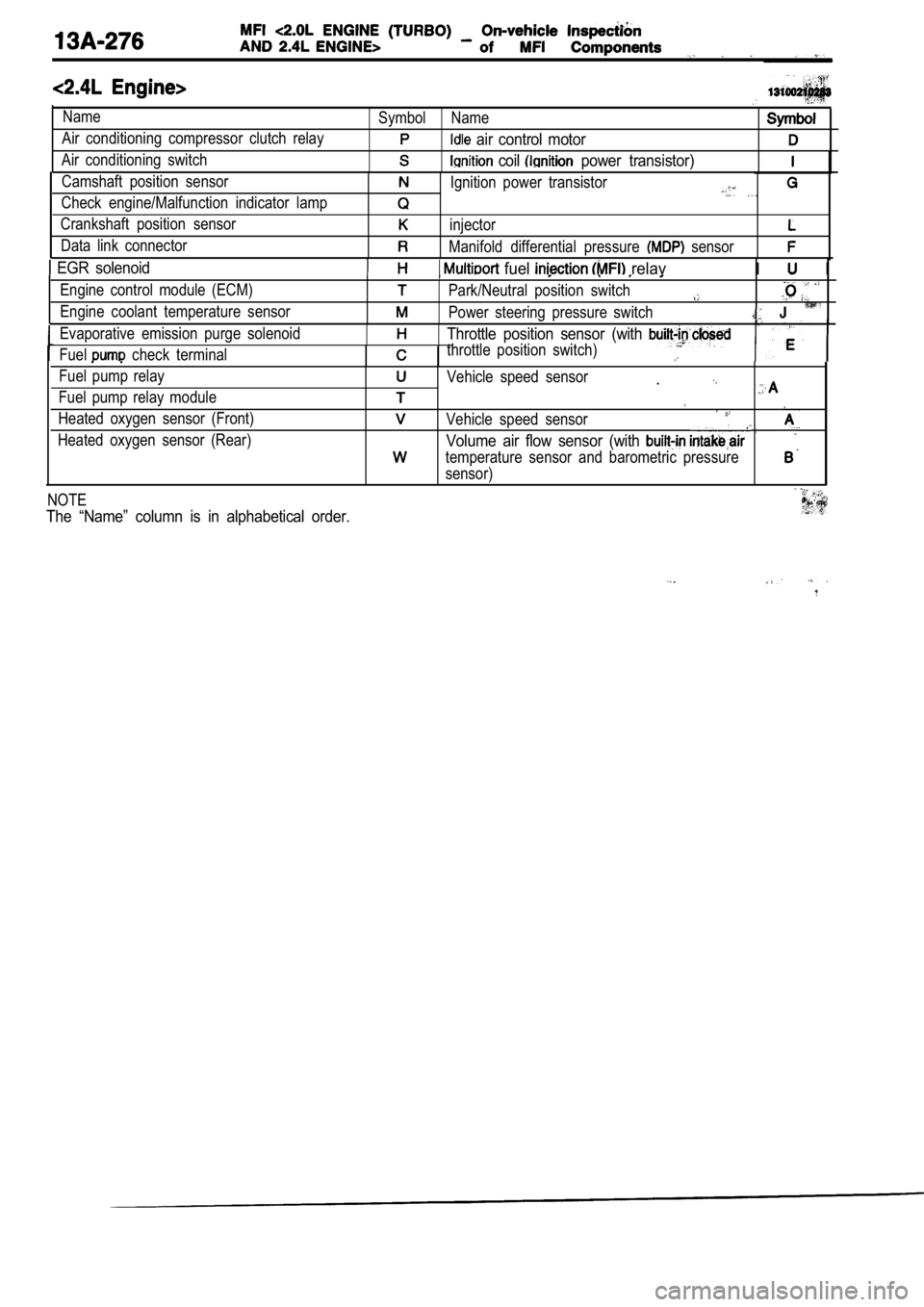
Name
Air conditioning compressor clutch relay
Air conditioning switchSymbol Name
air control motor
coil power transistor)
Camshaft position sensor
Check engine/Malfunction indicator lamp
Crankshaft position sensor
Data link connectorIgnition power transistor
injector
Manifold differential pressure sensor
EGR solenoid fuel relavI I
Engine control module (ECM)
Engine coolant temperature sensorPark/Neutral position switch
Power steering pressure switch
Evaporative emission purge solenoid
Fuel
check terminal
Throttle position sensor (with
throttle position switch)
Fuel pump relay
Fuel pump relay module
Heated oxygen sensor (Front)
Heated oxygen sensor (Rear)Vehicle speed sensor.
Vehicle speed sensor
Volume air flow sensor (with
temperature sensor and barometric pressure
sensor)
NOTE
The “Name” column is in alphabetical order.
Volume air flow sensor
side connector
Intake air temper-
ature sensor
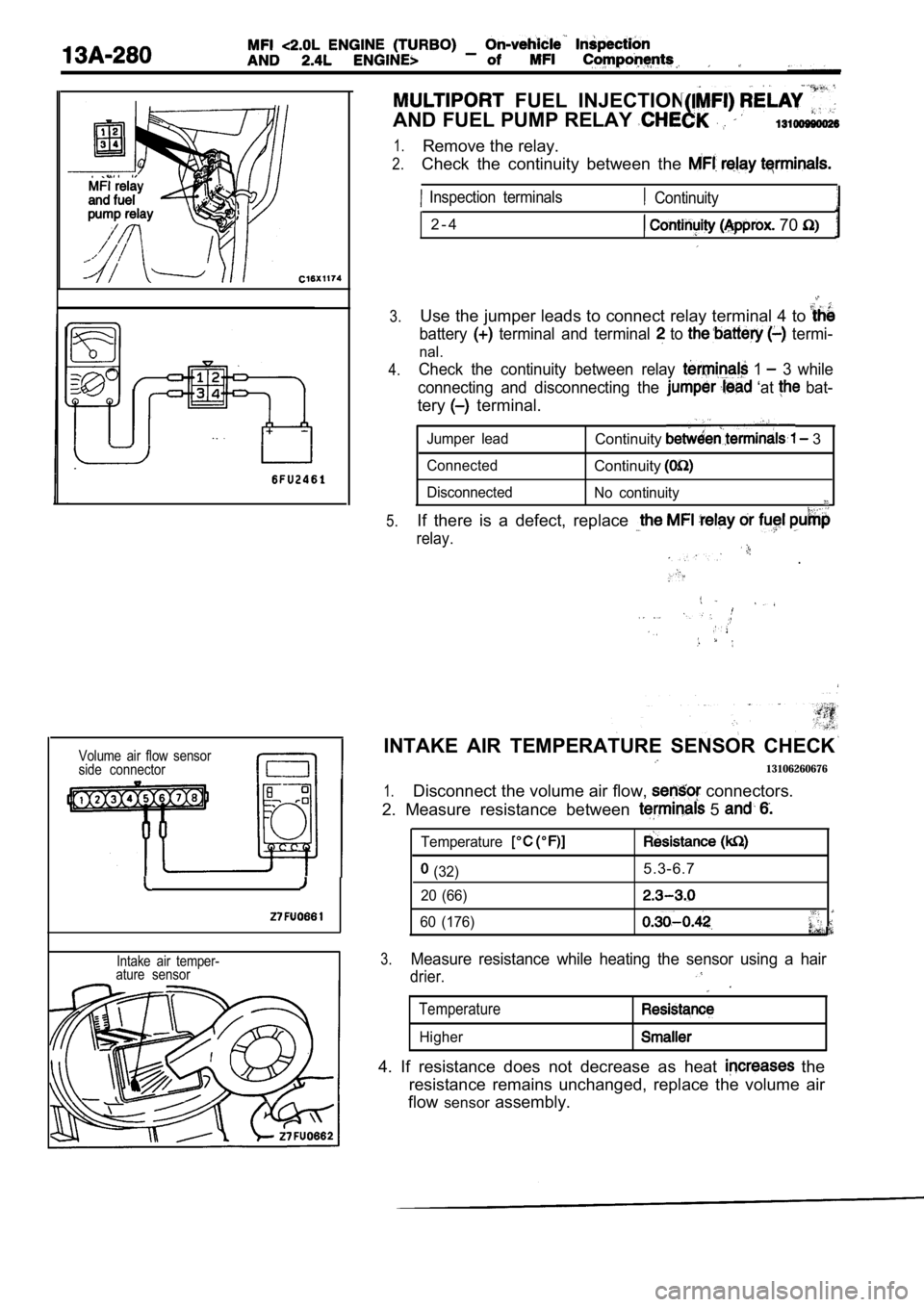
FUEL INJECTION
AND FUEL PUMP RELAY
1.
2.
3.
4.
5.
Remove the relay.
Check the continuity between the
Inspection terminals
2 - 4
Continuity
70
Use the jumper leads to connect relay terminal 4 to
battery terminal and terminal to termi-
nal.
Check the continuity between relay 1 3 while
connecting and disconnecting the
‘at bat-
tery terminal.
Jumper leadContinuity 3
ConnectedContinuity
Disconnected No continuity
If there is a defect, replace
relay.
.
INTAKE AIR TEMPERATURE SENSOR CHECK
13106260676
1.Disconnect the volume air flow, connectors.
2. Measure resistance between
5
Temperature
(32)
20 (66)
60 (176)5.3-6.7
3.Measure resistance while heating the sensor using a hair
drier.
Temperature
Higher
4. If resistance does not decrease as heat the
resistance remains unchanged, replace the volume ai r
flow sensor assembly.
