MITSUBISHI SPYDER 1990 Service Repair Manual
Manufacturer: MITSUBISHI, Model Year: 1990, Model line: SPYDER, Model: MITSUBISHI SPYDER 1990Pages: 2103, PDF Size: 68.98 MB
Page 791 of 2103
Emission
ENGINE AND CONTROL
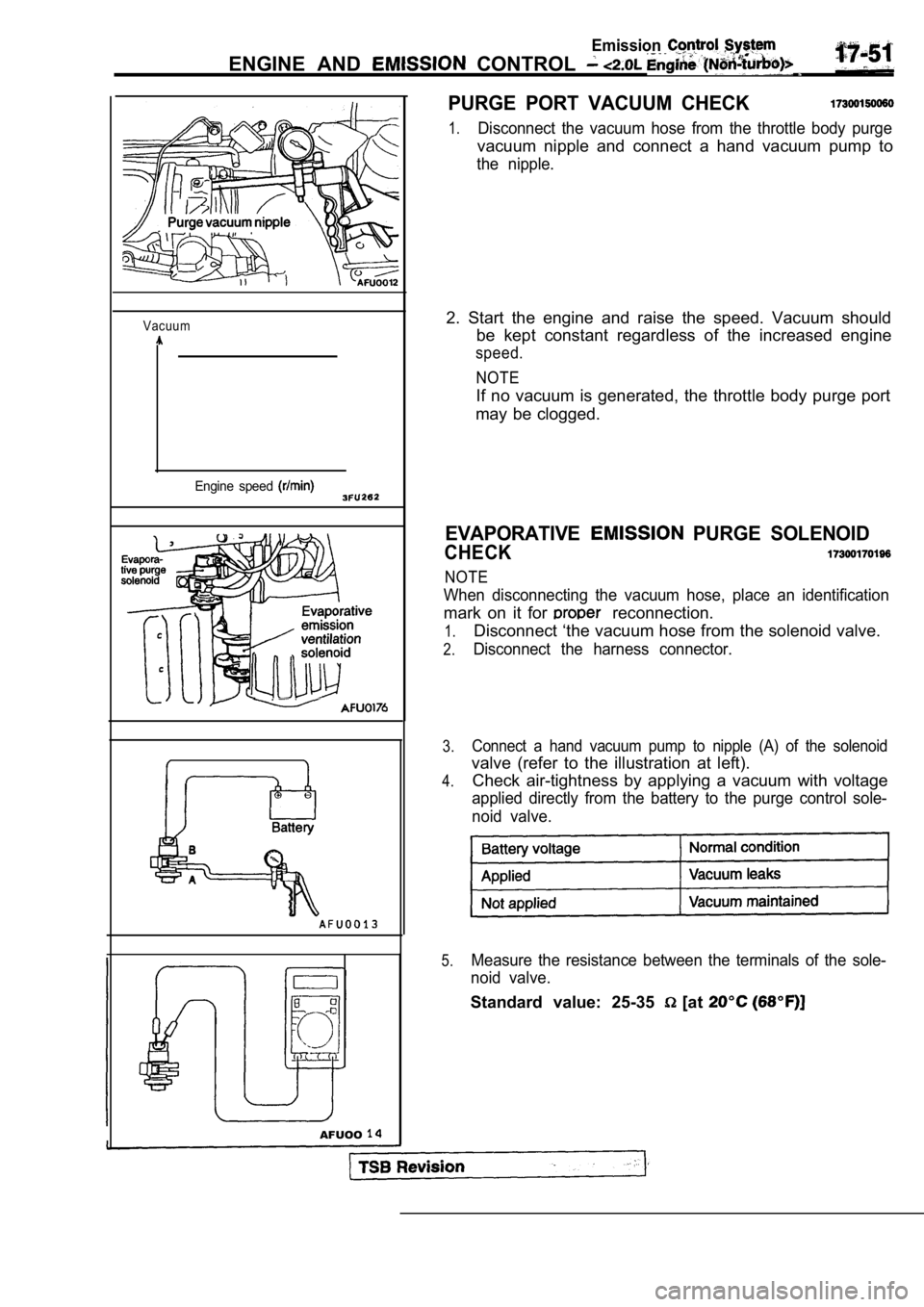
Vacuum
Engine speed
AFUOO
PURGE PORT VACUUM CHECK
1.Disconnect the vacuum hose from the throttle body purge
vacuum nipple and connect a hand vacuum pump to
the nipple.
2. Start the engine and raise the speed. Vacuum sho uld
be kept constant regardless of the increased engine
speed.
NOTE
If no vacuum is generated, the throttle body purge port
may be clogged.
EVAPORATIVE PURGE SOLENOID
CHECK
NOTE
When disconnecting the vacuum hose, place an identi fication
mark on it for reconnection.
1.
2.
3.
4.
5.
Disconnect ‘the vacuum hose from the solenoid valve .
Disconnect the harness connector.
Connect a hand vacuum pump to nipple (A) of the sol enoid
valve (refer to the illustration at left).
Check air-tightness by applying a vacuum with volta ge
applied directly from the battery to the purge control sole-
noid valve.
Measure the resistance between the terminals of the sole-
noid valve.
Standard value: 25-35 [at
Page 792 of 2103

ENGINE AND EMISSION CONTROL
ENGINE COOLANT TEMPERATURE SENSOR
AND INTAKE AIR TEMPERATURE SENSOR
To check these parts, refer to GROUP Troubleshooting.
AIR CONDITIONING SWITCH17300200031
To check the air conditioning switch, refer to GROU P 55
Air Conditioning Switch.
TSB Revision
Page 793 of 2103
Emission
ENGINE AND EMISSION CONTROL
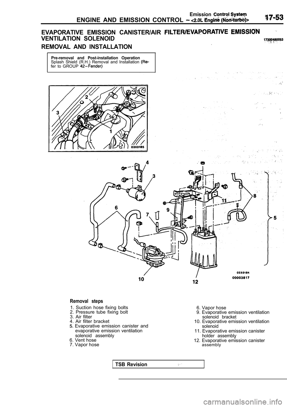
EVAPORATIVE EMISSION CANISTER/AIR
VENTILATION SOLENOID
REMOVAL AND INSTALLATION
Pre-removal and Post-installation OperationSplash Shield (R.H.) Removal and Installation fer to GROUP
Removal steps
1. Suction hose fixing bolts
2. Pressure tube fixing bolt
3. Air filter
4. Air filter bracket
Evaporative emission canister and
evaporative emission ventilation
solenoid assembly6. Vent hose7. Vapor hose 6. Vapor hose
9. Evaporative emission ventilation
solenoid bracket10. Evaporative emission ventilationsolenoid11. Evaporative emission canisterholder assemblv12. Evaporative emission canister assembly
TSB Revision
Page 794 of 2103
ENGINE AND EMISSION CONTROL
EXHAUST GAS
GENERAL INFORMATION
The EGR system reduces oxides in engine
exhaust and helps prevent detonation (engine
knock). The system allows a predetermined amount
of hot exhaust gas to recirculate and dilute theincoming air/fuel mixture. The diluted air/fuel mix -
ture reduces peak flame
during com-
bustion.
OPERATION
The electronic EGR transducer an electri-
cally operated solenoid and a back-pressure trans-
ducer. The
Control Module (PCM) con-
trols operation of the solenoid. Exhaust system
back-pressure controls the transducer.
When the PCM de-energizes the
vacuum
does not reach the transducer.
Vacuum only flows to the transducer when the PCM
energizes the solenoid.
When exhaust system back-pressure becomes high
enough, a bleed valve in the transducer closes.
The PCM energizes the solenoid and back-pressure
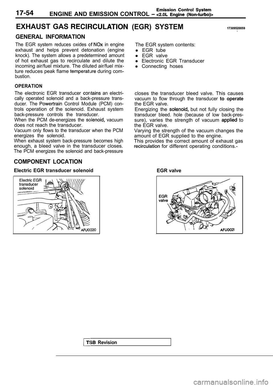
COMPONENT LOCATION
Electric EGR transducer solenoid
(EGR) SYSTEM17309520059
The EGR system contents:
l EGR tube
l EGR valve
l Electronic EGR Transducer
l Connecting hoses
closes the transducer bleed valve. This causes
vacuum to flow through the transducer to operate
the EGR valve. Energizing the
but not fully closing the
transducer bleed. hole (because of low back-pres-
sure), varies the strength of vacuum to
the EGR valve.
Varying the strength of the vacuum changes the
amount of EGR supplied to the engine.
This provides the correct amount of exhaust gas
for different operating conditions.-
EGR valve
Revision
Page 795 of 2103
Emission Control
Engine
C H E C K . .
To ensure proper operation of system, all
and moving parts must be free of
plugging or sticking.
Ensure that the system’ hoses do not leak.
Replace leaking components.
1.Check the EGR and valve with
engine fully warmed up and running coolant
perature over
2.With the transaxle in neutral and the allow.
the engine to idle seconds.
3. Abruptly accelerate the engine
approximately
but not over 3000
4, The valve ‘stem should move when accelerating
the engine. Repeat the test several- times-to
movement.
5.If the EGR valve stem moves, the control system is
ing normally.
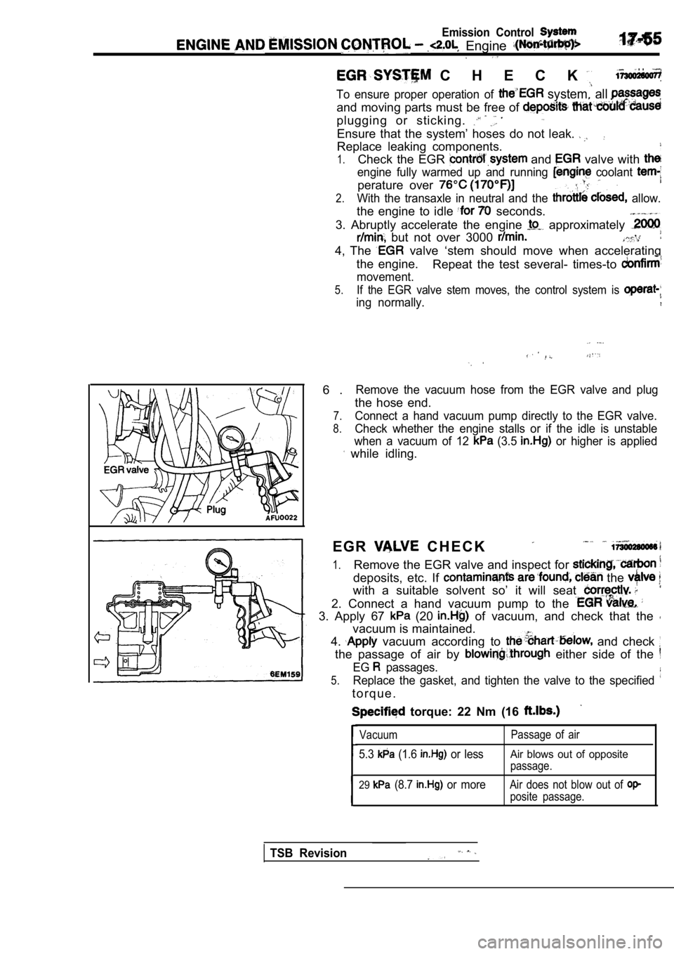
6 .Remove the vacuum hose from the EGR valve and plug
the hose end.
7.Connect a hand vacuum pump directly to the EGR valv e.
8.Check whether the engine stalls or if the idle is unstable
when a vacuum of 12
(3.5 or higher is applied
while idling.
E G R
C H E C K
1.Remove the EGR valve and inspect for
deposits, etc. If the
with a suitable solvent so’ it will seat
2. Connect a hand vacuum pump to the
3. Apply 67 (20 of vacuum, and check that the
vacuum is maintained.
4.
vacuum according to and check
the passage of air by either side of the
EG passages.
5.Replace the gasket, and tighten the valve to the sp ecified
t o r q u e .
torque: 22 Nm (16
Vacuum
5.3 (1.6 or less
Passage of air
Air blows out of opposite
passage.
29 (8.7 or moreAir does not blow out of
posite passage.
TSB Revision
Page 796 of 2103
ENGINE AND
Emission Control System
Vacuum
Engine speed
TSB Revision
4I
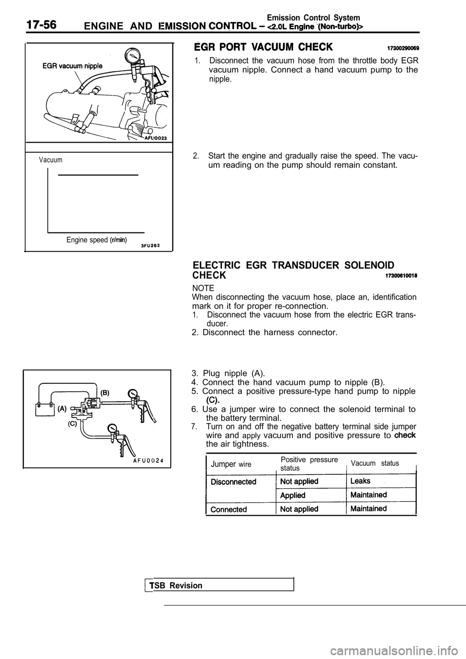
1.Disconnect the vacuum hose from the throttle body EGR
vacuum nipple. Connect a hand vacuum pump to the
nipple.
2.Start the engine and gradually raise the speed. The vacu-
um reading on the pump should remain constant.
ELECTRIC EGR TRANSDUCER SOLENOID
CHECK
NOTE
When disconnecting the vacuum hose, place an, ident ification
mark on it for proper re-connection.
1.Disconnect the vacuum hose from the electric EGR trans-
ducer.
2. Disconnect the harness connector.
3. Plug nipple (A).
4. Connect the hand vacuum pump to nipple (B).
5. Connect a positive pressure-type hand pump to ni pple
6. Use a jumper wire to connect the solenoid terminal to
the battery terminal.
7.Turn on and off the negative battery terminal side jumper
wire and applyvacuum and positive pressure to
the air tightness.
JumperwirePositive pressure
status
IVacuum statusI
Page 797 of 2103
Emission Control
AND EMISSION CONTROL
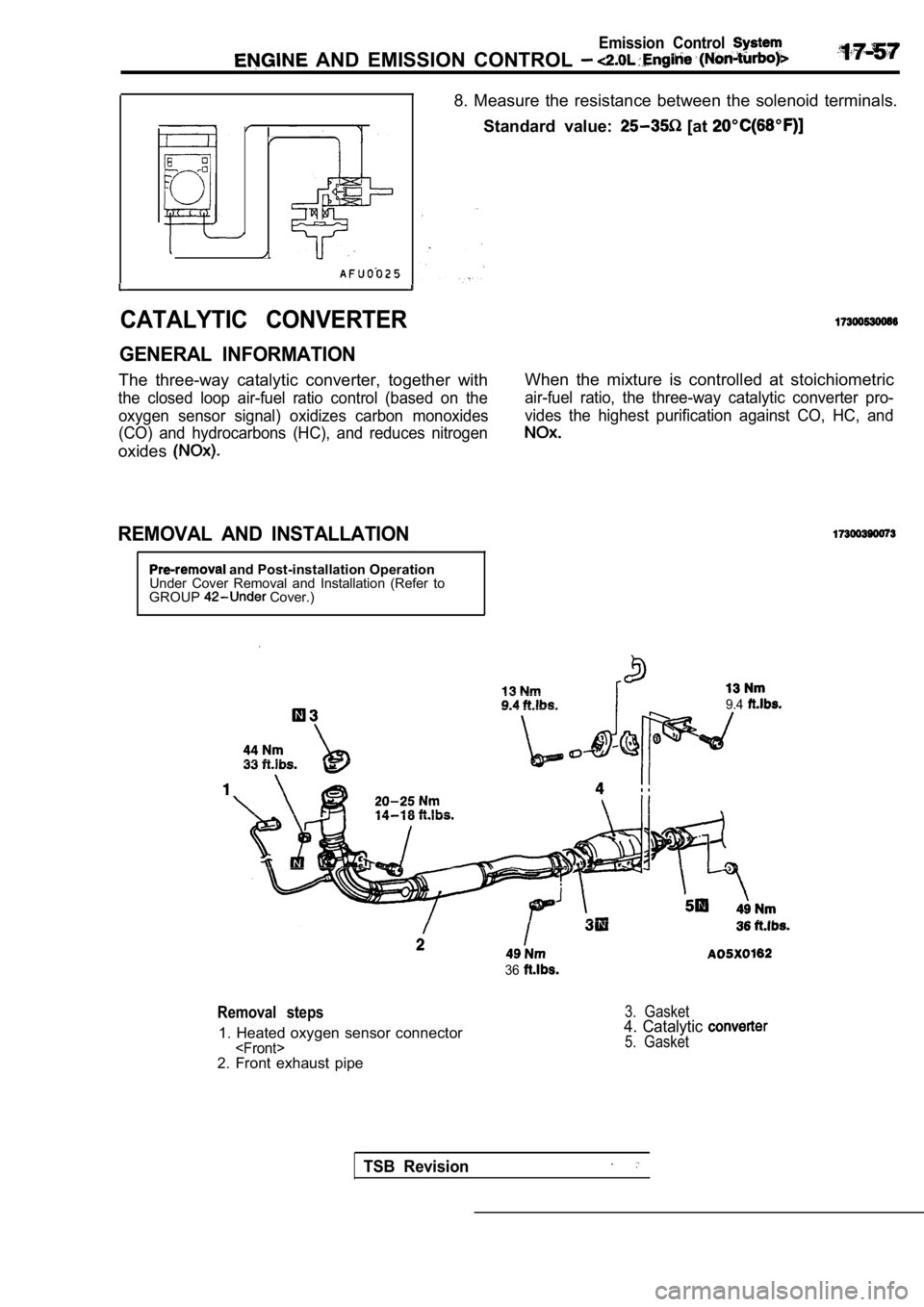
8. Measure the resistance between the solenoid terminals.
Standard value:
[at
CATALYTIC CONVERTER
GENERAL INFORMATION
The three-way catalytic converter, together with
the closed loop air-fuel ratio control (based on th e
oxygen sensor signal) oxidizes carbon monoxides
(CO) and hydrocarbons (HC), and reduces nitrogen
oxides
REMOVAL AND INSTALLATION
and Post-installation Operation
Under Cover Removal and Installation (Refer to
GROUP
Cover.) When the mixture is controlled at stoichiometric
air-fuel ratio, the three-way catalytic converter p
ro-
vides the highest purification against CO, HC, and
9.4
36
Removal steps
1. Heated oxygen sensor connector
3. Gasket4. Catalytic 5. Gasket
TSB Revision
Page 798 of 2103

ENGINE AND EMISSION CONTROL
INSPECTION
Check for damage, cracking or deterioration. Replace if faulty.
Caution
1. Stop the engine immediately if engine misfiring
occurs, otherwise an abnormally hot exhaust system
will damage the catalytic converter or other underb ody
parts.
2.
Correct and repair the ignition or fuel system if t here
are malfunctions, otherwise engine misfiring may
occur which will damage the catalytic converter.
3. Observe manufacturer’s specifications when doing
service work.
TSB Revision
Page 799 of 2103
(Turbo) 2.41 Engines
GENERAL INFORMATION
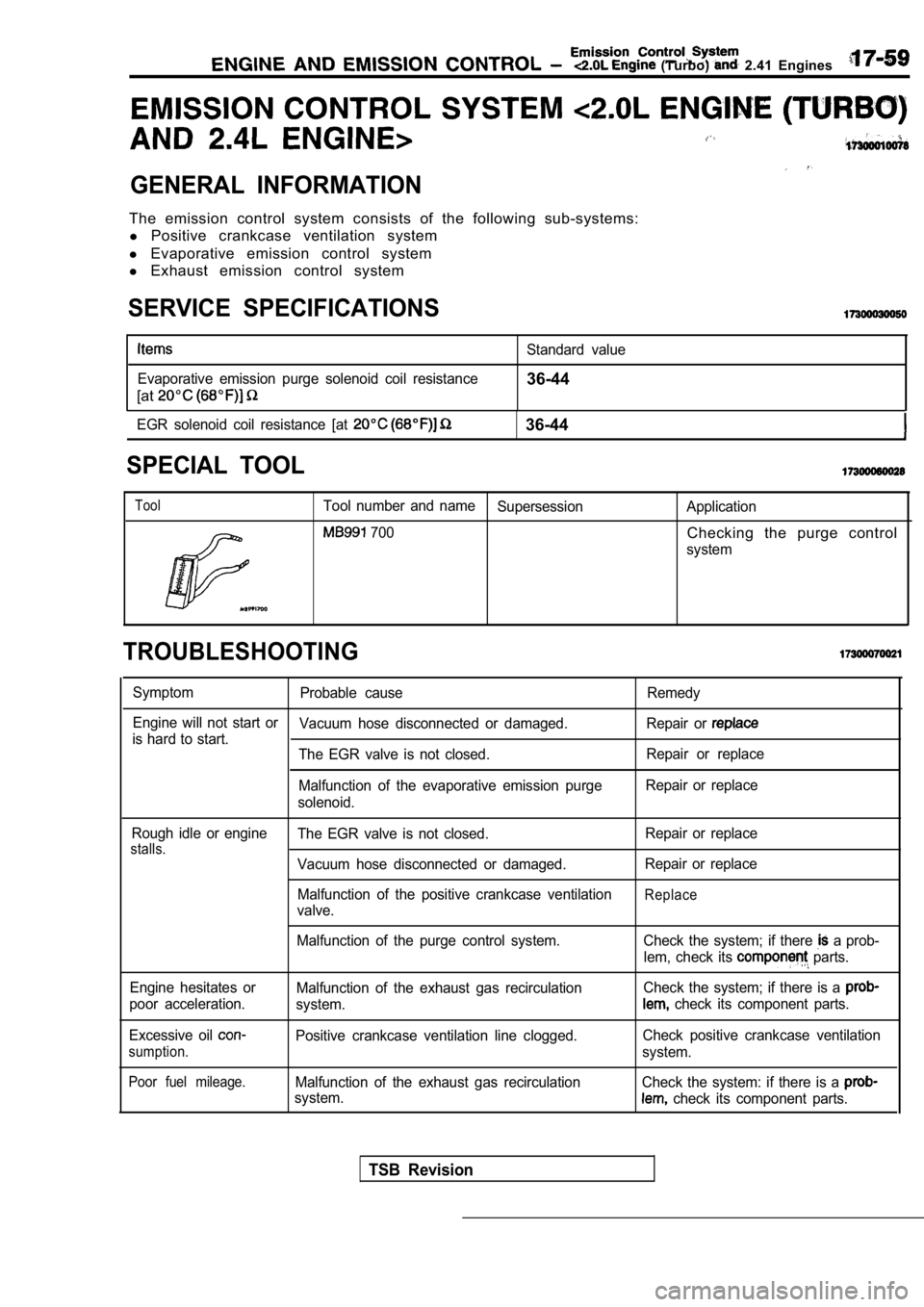
The emission control system consists of the following sub-systems:
l Positive crankcase ventilation system
l Evaporative emission control system
l Exhaust emission control system
SERVICE SPECIFICATIONS
Evaporative emission purge solenoid coil resistance
[at
Standard value
36-44
EGR solenoid coil resistance [at 36-44
SPECIAL TOOL
ToolTool number and name
Supersession Application
700Checking the purge control
system
TROUBLESHOOTING
SymptomProbable cause Remedy
Engine will not start or Vacuum hose disconnected or damaged. Repair or
is hard to start.
The EGR valve is not closed. Repair or replace
Malfunction of the evaporative emission purge Repair or replace
solenoid.
Rough idle or engine
stalls.The EGR valve is not closed.
Vacuum hose disconnected or damaged.
Malfunction of the positive crankcase ventilation
valve. Repair or replace
Repair or replace
Replace
Malfunction of the purge control system.
Engine hesitates or
poor acceleration.
Excessive oil
sumption.
Poor fuel mileage.
Malfunction of the exhaust gas recirculation
system.
Positive crankcase ventilation line clogged.
Malfunction of the exhaust gas recirculation
system. Check the system; if there
a prob-
lem, check its
parts.
Check the system; if there is a
check its component parts.
Check positive crankcase ventilation
system.
Check the system: if there is a
check its component parts.
TSB Revision
Page 800 of 2103
(Turbo) and Engine>
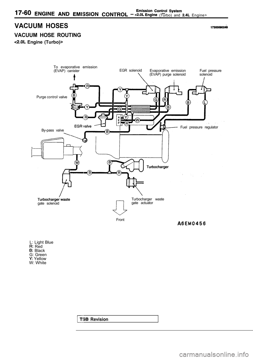
VACUUM HOSES
VACUUM HOSE ROUTING
Engine (Turbo)>To evaporative emission
(EVAP) canisterEGR solenoidEvaporative emissionFuel pressure(EVAP) purge solenoid solenoid
I
Purgecontrol valve
By-pass valveFuel pressure regulator
Revision
Turbocharger waste
gate solenoidgate actuator
Front
L: Light Blue Red Black
G: Green
Yellow
W: White