MITSUBISHI SPYDER 1990 Service Repair Manual
SPYDER 1990
MITSUBISHI
MITSUBISHI
https://www.carmanualsonline.info/img/19/57345/w960_57345-0.png
MITSUBISHI SPYDER 1990 Service Repair Manual
Trending: turn signal, seat memory, ABS, gas mileage, alarm, automatic transmission, length
Page 821 of 2103
ENGINE AND EMISSION CONTROL Engine (Turbo) end
Engine>
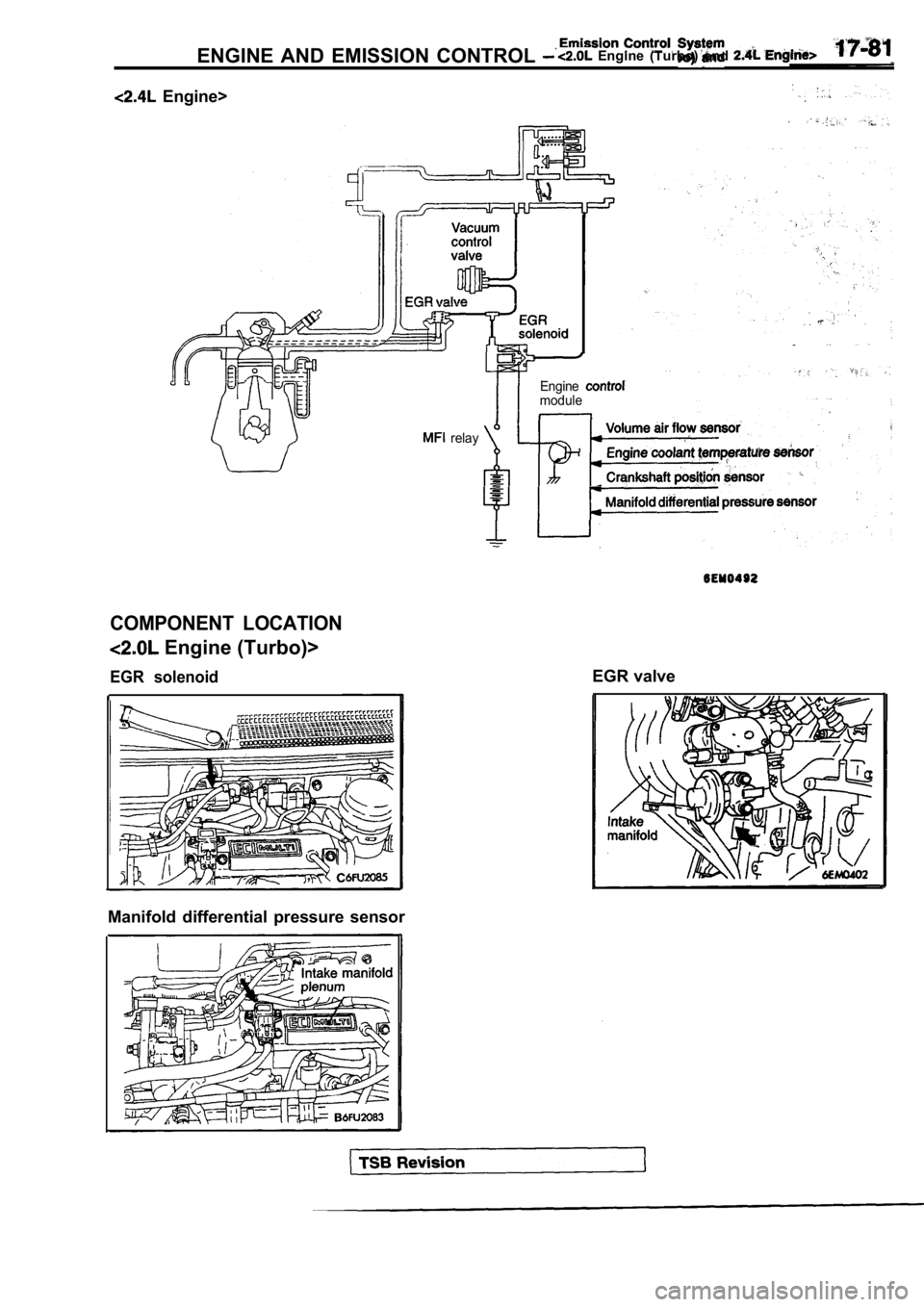
COMPONENT LOCATION
Engine (Turbo)>
EGR solenoid
Manifold differential pressure sensor
relayEngine
module
EGR valve
Page 822 of 2103
Engine (Turbo) and Engine>
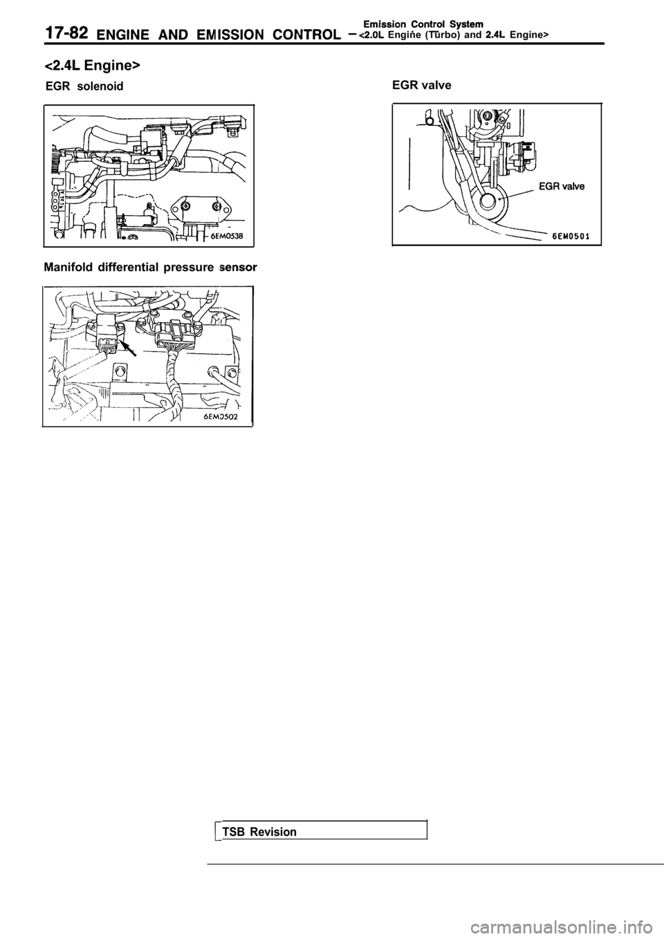
Engine>
EGR solenoidEGR valve
Manifold differential pressure
TSB Revision
Page 823 of 2103
Emission Control
ENGINE AND EMISSION CONTROL Engine
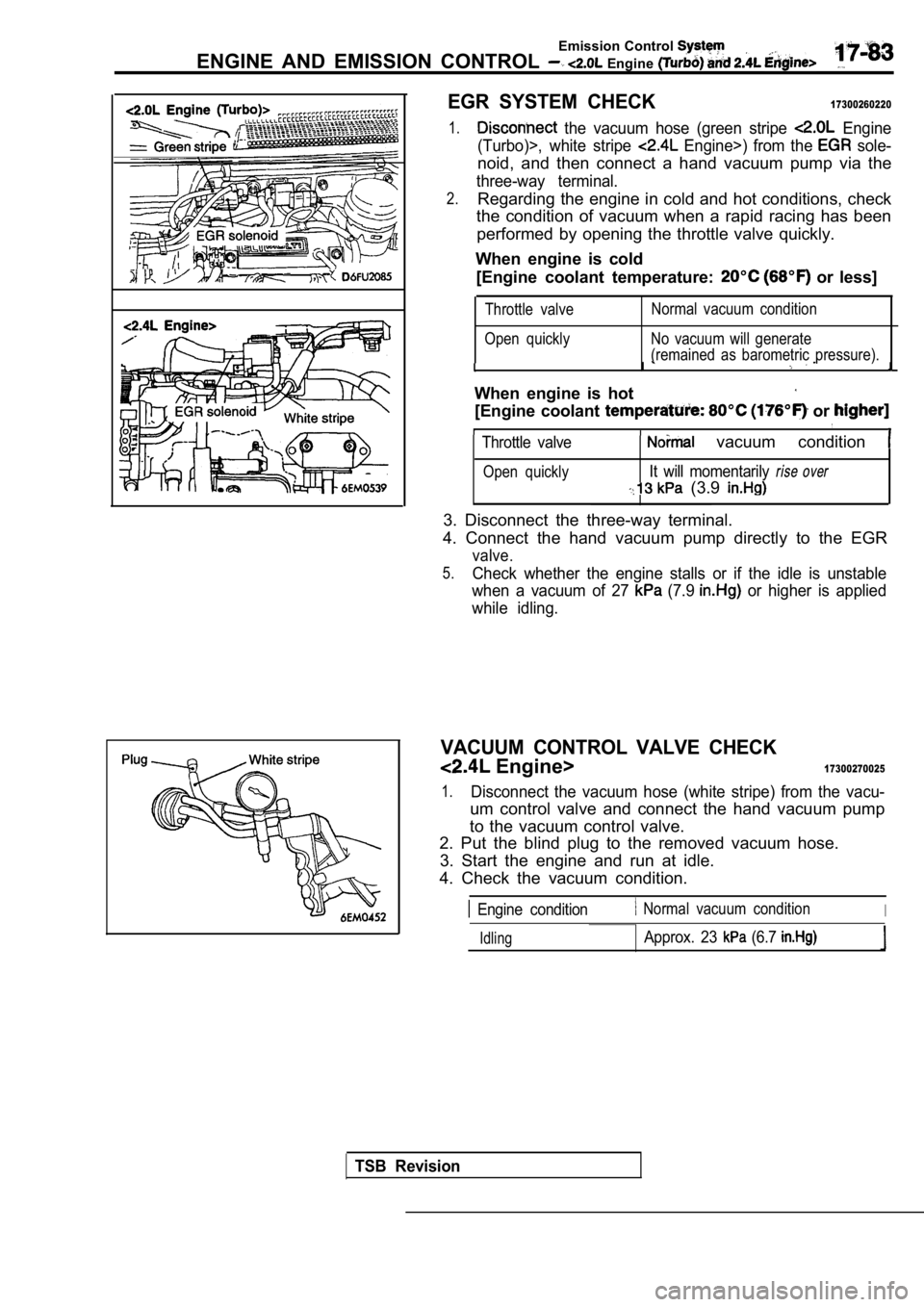
EGR SYSTEM CHECK17300260220
1. the vacuum hose (green stripe Engine
(Turbo)>, white stripe
Engine>) from the sole-
noid, and then connect a hand vacuum pump via the
three-way terminal.
2.Regarding the engine in cold and hot conditions, ch eck
the condition of vacuum when a rapid racing has bee n
performed by opening the throttle valve quickly.
When engine is cold [Engine coolant temperature:
or less]
Throttle valve
Open quickly Normal vacuum condition
No vacuum will generate
(remained as barometric pressure).
I
When engine is hot
[Engine coolant or
Throttle valve vacuum condition
Open quicklyIt will momentarily rise over
(3.9
3. Disconnect the three-way terminal.
4. Connect the hand vacuum pump directly to the EGR
valve.
5.Check whether the engine stalls or if the idle is u nstable
when a vacuum of 27
(7.9 or higher is applied
while idling.
VACUUM CONTROL VALVE CHECK
Engine>17300270025
1.Disconnect the vacuum hose (white stripe) from the vacu-
um control valve and connect the hand vacuum pump
to the vacuum control valve.
2. Put the blind plug to the removed vacuum hose.
3. Start the engine and run at idle.
4. Check the vacuum condition.
Engine condition Normal vacuum conditionI
IdlingApprox. 23 (6.7
TSB Revision
Page 824 of 2103
(Turbo) and Engine>
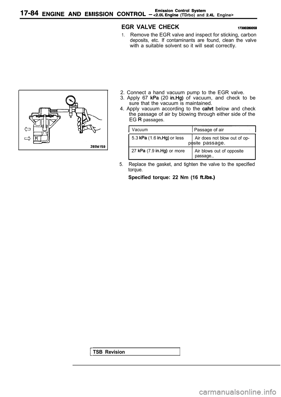
EGR VALVE CHECK
1.Remove the EGR valve and inspect for sticking, carbon
deposits, etc. If contaminants are found, clean the valve
with a suitable solvent so it will seat correctly.
2. Connect a hand vacuum pump to the EGR valve.
3. Apply 67
(20 of vacuum, and check to be
sure that the vacuum is maintained.
4. Apply vacuum according to the
below and check
the passage of air by blowing through either side o f the
EG
passages.
Vacuum Passage of air
5.3 (1.6 or lessAir does not blow out of op-
posite passage.
27 (7.9 or more
Air blows out of opposite
passage.,
5.Replace the gasket, and tighten the valve to the sp ecified
torque.
Specified torque: 22 Nm (16
TSB Revision
Page 825 of 2103
and
Engine
Engine>
Vacuum
Enginespeed
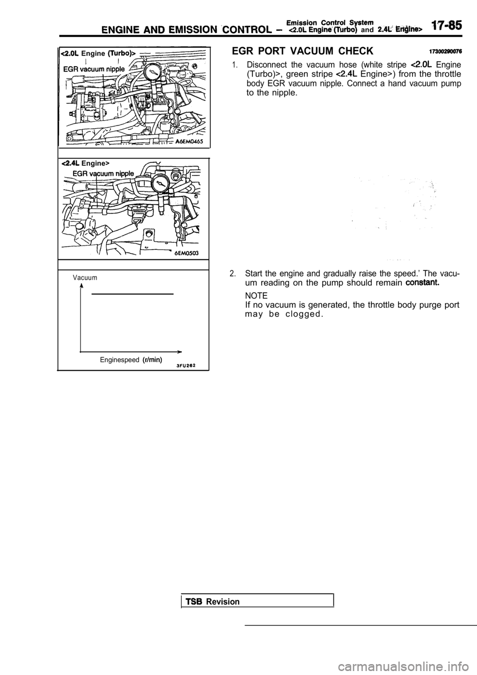
EGR PORT VACUUM CHECK
1.Disconnect the vacuum hose (white stripe Engine
(Turbo)>, green stripe Engine>) from the throttle
body EGR vacuum nipple. Connect a hand vacuum pump
to the nipple.
2.Start the engine and gradually raise the speed.’ The vacu-
um reading on the pump should remain
NOTE
If no vacuum is generated, the throttle body purge port
m a y b e c l o g g e d .
Revision
Page 826 of 2103
E N G I N E A N D E M I S S I O N C O N T R O L ( T u r b o )
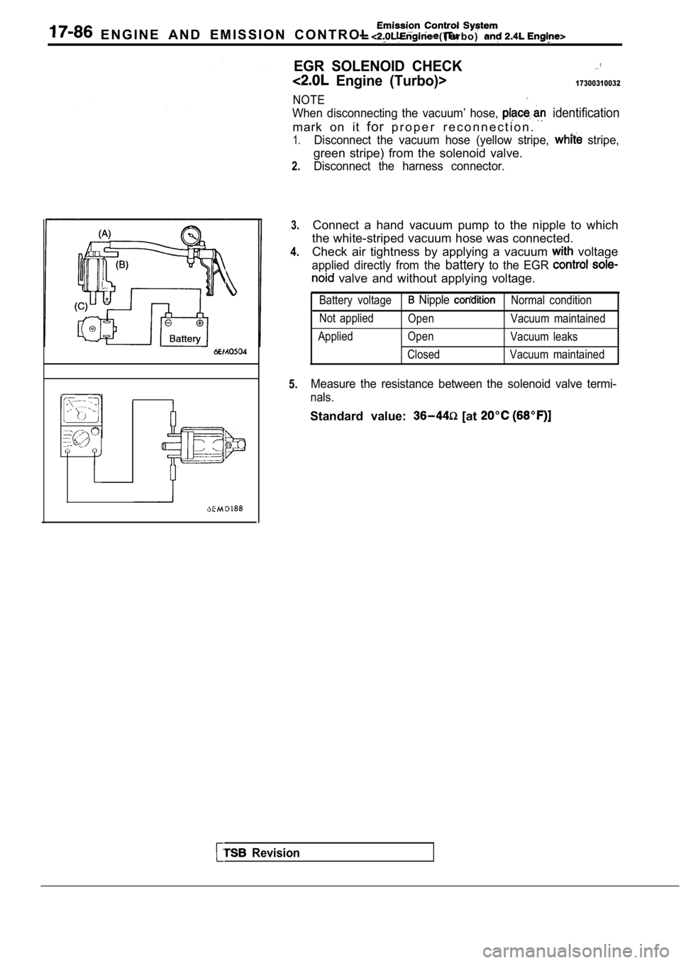
EGR SOLENOID CHECK
Engine (Turbo)>17300310032
NOTE
When disconnecting the vacuum’ hose, identification
mark on it forp r o p e r r e c o n n e c t i o n .
1.
2.
3.
4.
5.
Disconnect the vacuum hose (yellow stripe, stripe,
green stripe) from the solenoid valve.
Disconnect the harness connector.
Connect a hand vacuum pump to the nipple to which
the white-striped vacuum hose was connected.
Check air tightness by applying a vacuum
voltage
applied directly from the batteryto the EGR
valve and without applying voltage.
Battery voltage Nipple Normal condition
Not applied Open Vacuum maintained
Applied Open Vacuum leaks
Closed Vacuum maintained
Measure the resistance between the solenoid valve t ermi-
nals.
Standard value: [at
Revision
Page 827 of 2103
AND EMISSION CONTROL
Emission Engine
27
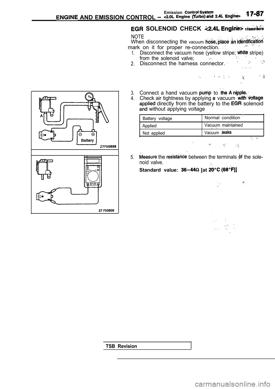
SOLENOID CHECK
NOTE,
When disconnecting the vacuum
mark on it for proper re-connection.
Disconnect the vacuum hose (yellow stripe; stripe)1.
2.
3.
4.
5.
from the solenoid valve;
Disconnect the harness connector.
Connect a hand vacuum to
Check air tightness by applying vacuum
directly from the battery to the solenoid
without applying voltage
Battery voltage
Applied Not appliedNormal condition
Vacuum maintained.
Vacuum
the between the terminals the sole-
noid valve.
Standard value: [at
.
,
TSB Revision
Page 828 of 2103
Emission Control System ENGINE AND EMISSION CONTROL Engine (Turbo) and
CATALYTIC CONVERTER17399939993
GENERAL INFORMATION
The three-way catalytic converter, together with
the closed loop air-fuel ratio control (based on the
oxygen sensor signal) oxidizes carbon monoxides
(CO) and hydrocarbons (HC), and reduces nitrogen
oxides
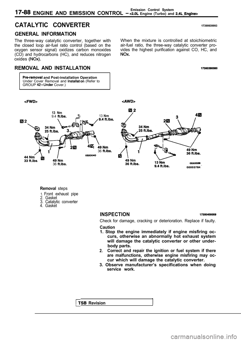
REMOVAL AND INSTALLATION
When the mixture is controlled at stoichiometric
air-fuel ratio, the three-way catalytic converter p ro-
vides the highest purification against CO, HC, and
and Post-installation Operation
Under Cover Removal and (Refer to
GROUP Cover.)
13 Nm9.413Nm
I36
. .
Revision
36
Removalsteps
1.Front exhaust pipe2. Gasket3. Catalytic converter4. Gasket
INSPECTION
Check for damage, cracking or deterioration. Replac e if faulty.
Caution
1. Stop the engine immediately if engine misfiring oc-
curs, otherwise an abnormally hot exhaust system
will damage the catalytic converter or other under- body parts.
2.Correct and repair the ignition or fuel system if t here
are malfunctions, otherwise engine misfiring may oc -
cur which will damage the catalytic converter.
3. Observe manufacturer’s specifications when doing
service work.
Page 829 of 2103
CLUTCH
CONTENTS
CLUTCH. . . . . . . . . . . . . . . . . . . . . . . . . . . . . . . . . . . . . . . . . . . . . . . . . . .. . .
CLUTCHOVERHAUL . . . . . . . . . . . . . . . . . . . . . . . . . . . . . . . . . . . . . . . . . .
Page 830 of 2103
Trending: jump cable, wheel bolts, change key battery, engine coolant, spark plugs replace, steering wheel adjustment, turn signal
