NISSAN ALMERA N15 1995 Service Manual
Manufacturer: NISSAN, Model Year: 1995, Model line: ALMERA N15, Model: NISSAN ALMERA N15 1995Pages: 1701, PDF Size: 82.27 MB
Page 1021 of 1701

EC-IGN/SG-01
G
m
30A
OJ
Refer
toEL-POWER.
-:Detectable line
for OTC
-: Non-detectable
line forDTC
n
BIY BB
t.J
!
m m
DISTRIBUTOR
m")
TROUBLEDIAGNOSIS FORDTC21
Ignition Signal
(Cont'd)
EC-IGN/SG-01
G
m
30A
OJ
Refer
toEL-POWER.
-:Detectable line
for OTC
-: Non-detectable
line forDTC
n
BIY BB
t.J
!
m m
DISTRIBUTOR
m
@
~~
W/B B/W
t
I'
ToEC"
.- BIY
+
(EGGS contra 1
~ module)
CONDENSER
POWER TRANSISTOR
~
G
I'
G
W
RESISTOR
~
2
GY/R W/B
m m
IGN IGN
CK
ECM
(EGCS
CONTROL
MODULE)
L- ---l
CED
IGNITION
COIL
BIR
w+fl
t
SPARK PLUG
ST
IGNITION
SWITCH
'
....
ACG
~
BIR
db~
I~ICMID
BIR
IUJI@
=r
BIR
OFF
~ (E114)
tmIID
W
fill
I
lfi]
Cffi
3456 W
r--------------------~
I I
I I
I
I:XI
m~@1
: (11213141516)
GY
CZIID
GY:
I I
L
~
Refer
tolast page
(Foldout page).
(IT)
L
HEC006
EC-302
Page 1022 of 1701

•
Check
thefollowing.
• Harness connectors
QD,@
• Harness connectors
@,@D
• Harness foropen or
short between ignition
coil and ignition switch
If NG, repair harness or
connectors.
Yes
NG
INSPECTION
START
OK
Turn
ignition switch"OFF". andrestart
engine.
Is engine running?
CHECK POWER SUPPLY.
1. Turn ignition switch"OFF".
2. Disconnect ignitioncoilharness con-
nector.
3. Turn ignition switch"ON".
4. Check voltage between terminal
(J)
and ground withCONSULT or
tester.
Voltage: Batteryvoltage
SEF010P
TROUBLE
DIAGNOSIS FORDTe21
Ignition Signal(Cont'd)
DIAGNOSTIC PROCEDURE
CHECK GROUND CIRCUIT.
AEC69a
1.Turn ignition switch"OFF".
2. Disconnect powertransistor harness
connector.
3. Check harness continuity between
terminal
@
and engine ground.
Continuity shouldexist.
If
OK. check harness forshort.
~i5
@a
~ SEF4690
~iv
~i5
II
ECM
'gCONNECTORII
(1!2IffllsI6) CHECK
INPUTSIGNAL CIRCUIT.
1. Disconnect ECMharness connector.
2. Check harness continuity between
ECM terminal
G)
and power transis-
tor terminal
G).
Continuity shouldexist.
If OK. check harness forshort.
OK
CHECK COMPONENTS
(Ignition coil,power transistor).
Refer to"COMPONENT INSPECTION".
EC-305. NG
NG
NG
Repair
harness orcon-
nectors.
Repair harness orcon-
nectors.
Replace malfunctioning
component(s).
OK
SEF4700
Disconnect andreconnect harnesscon-
nectors inthe circuit. Thenretest.
Trouble isnot fixed.
Check ECMpinterminals fordamage
and check theconnection ofECM har-
ness connector. ReconnectECMhar-
ness connector andretest.
INSPECTION END
EC-303
Page 1023 of 1701
.
Refer to\"COMPONENT INSPECTION\"
on next page.
CHECK
INPUTSIGNAL CIRCUIT.
1. Stop engine.
2. Disconnect ign")
Repairharness orcon-
nectors.
Replace resistor.
NG
NG
CHECK COMPONENT
(Resistor).
Refer to"COMPONENT INSPECTION"
on next page.
CHECK
INPUTSIGNAL CIRCUIT.
1. Stop engine.
2. Disconnect ignitioncoilharness con-
nector.
3. Strip tapecovering resistor.
4. Disconnect ECMharness connector.
5. Check harness continuity between
ignition coilterminal
CID
and resistor
terminal
(!).
resistor terminal
@
and ECM terminal
@.
Continuity shouldexist.
If OK, check harness forshort.
OK
TROUBLE
DIAGNOSIS FORDTC21
Ignition Signal(Cont'd)
@
SEF471Q
(;J~i5
~i5
1
~~Q~
'Cf~OONNlliOR~
LllJ
~i5
cffu
[ill
Disconnectandreconnect harnesscon-
nectors inthe circuit. Thenretest.
Trouble isnot fixed.
Check ECMpinterminals fordamage
and check theconnection ofECM har-
ness connector. Reconnect ECMhar-
ness connector andretest.
INSPECTION END
EC-304
Page 1024 of 1701
![NISSAN ALMERA N15 1995 Service Manual
•
Approximately
25kQ
Resistance
[at25'C (77'F)]
0.5 -1.0Q
Terminal
(J) -@
(Primary coil)
(J) -
@
(Secondary coil)
For checking secondary coil,remove distributor capand
measure resis](/img/5/57349/w960_57349-1023.png "NISSAN ALMERA N15 1995 Service Manual
•
Approximately
25kQ
Resistance
[at25'C (77'F)]
0.5 -1.0Q
Terminal
(J) -@
(Primary coil)
(J) -
@
(Secondary coil)
For checking secondary coil,remove distributor capand
measure resis")
•
Approximately
25kQ
Resistance
[at25'C (77'F)]
0.5 -1.0Q
Terminal
(J) -@
(Primary coil)
(J) -
@
(Secondary coil)
For checking secondary coil,remove distributor capand
measure resistance betweencoiltower metaltip
@
and
terminal
(f).
If NG, replace distributor assemblyasaunit.
Ignition
coil
1. Disconnect ignitioncoilharness connector.
2. Check resistance asshown inthe figure.
AEC902
MEC719B
TROUBLE
DIAGNOSIS FORDTC21
Ignition Signal(Cont'd)
COMPONENT INSPECTION
LCoiltower meta/tip
Powertransistor
1. Disconnect camshaftpositionsensor
&
power transistor
harness connector andignition coilharness connector.
2. Check power transistor resistance betweenterminals
CID
and
@.
Terminals Resistance
Result
NotOQ
OK
@
and
@
on
NG
If NG, replace distributor assembly.
Resistor
1. Disconnect resistorharness connector.
2. Check resistance betweenterminals
CD
and
CID
Resistance:
Approximately
2.2kQ
[at
25°C (77°F»
If NG, replace resistor.
EC-305
Page 1025 of 1701

The knock sensor isattached tothe cylinder block.Itsenses
engine knocking usingapiezoelectric element.Aknocking
vibr
ion
fromthecylinder blockissensed as")
TROUBLEDIAGNOSIS FORDTC34
Knock Sensor (KS)
The knock sensor isattached tothe cylinder block.Itsenses
engine knocking usingapiezoelectric element.Aknocking
vibr
ion
fromthecylinder blockissensed asvibrational pres-
sure. Thispressure is
converted
intoa
voltage
signalandsent
to the ECM.
PIEZO-ELEMENT SEF598K
Diagnostic
Trouble Code Malfunctionisdetected when....
No.
34 •An excessively loworhigh voltage fromtheknock
sensor issent toECM. Check
Items
(Possible Cause)
• Harness orconnectors
(The knock sensor circuitisopen orshorted.)
• Knock sensor
DIAGNOSTIC TROUBLECODECONFIRMATION
PROCEDURE
fiii\
1)Turn ignition switch"ON"andselect "DATA
\J!}
MONITOR" modewithCONSULT.
2) Start engine andrunitfor atleast 5seconds atidle
speed.
----------OR -----------
1) Start engine andrunitfor atleast 5seconds atidle
speed.
2) Turn ignition switch"OFF", waitatleast 7seconds
and then turn"ON".
3) Perform "Diagnostic TestMode II"(Self-diagnostic
results) withECM.
EC-306
Page 1026 of 1701
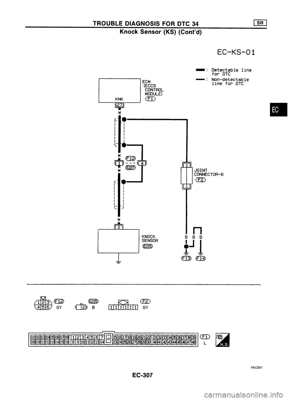
TROUBLEDIAGNOSIS FORDTC34
Knock Sensor (KS)(Cont'd)
EC-KS-01
rn
JOINT
CONNECTOR-6
@
1
ECM
(ECCS
CONTROL
MOOULE)
(IT)
KNK
1
2';
I
W
f .--------.
I I
I I
I I
I I
I I
I I
,,:"
.
w~
w
@Z)
f •
I I
I I
I I
I I
I I
I I
I:: )
-:
Detectable line
for DTC
-: Non-detectable
line forDTC
•
KNOCK
SENSOR
~
~m>
~GY
~@
I.IIIIIIII1lII
GY
em
L
HEC007
EC-307
Page 1027 of 1701

Repairharness orcon-
nectors.
Repair harness orcon-
nectors.
Replace knocksensor.
NG
~
INSPECTION
START
Loosen andretighten engineground
screws.
OK
Disconnect andreconnect harnesscon-
nectors inthe circuit. Thenretest.
OK
CHECK COMPONENT
(Knock sensor).
Refer to"COMPONENT INSPECTION"
below.
Troubleisnot fixed.
Check ECMpinterminals fordamage
and check theconnection ofECM har-
ness connector. ReconnectECMhar-
ness connector andretest,
OK
m
CHECK SUB.HARNESS CIRCUIT.
1. Disconnect knocksensor harness
connector.
2. Check harness continuity between
knock sensor harness connector ter-
minal
@
and knock sensor sub-har-
ness connector terminal
CD.
Continuity shouldexist.
If
OK, check harness forshorl.
fa
CHECK INPUTSIGNAL CIRCUIT.
1. Turn ignition switch"OFF".
2. Disconnect ECMharness connector
and knock sensor harness connector.
3. Disconnect sub-harness connectors
@,@D.
4. Check harness continuity between
terminal
CD
and ECM terminal
@.
Continuity shouldexist.
If OK, check harness forshorl.
MEC757B
MEC7568
TROUBLE
DIAGNOSIS FORDTC34
Knock Sensor (KS)(Cont'd)
DIAGNOSTIC PROCEDURE
~15
..
~
\ili:tV
~~
\tiiliJ
~15
ECM
BCONNECTORII
27
,,~n~(
r\r~\//\ \
AY
..("'~Inlake manifold
~
\
fa
II
INSPECTIONEND
COMPONENT INSPECTION
Knock sensor
• Use anohmmeter whichcanmeasure morethan10MO.
1. Disconnect knocksensor harness connector.
2. Check resistance betweenterminal
@
and ground.
Resistance: 500-620 kO[at25°C (77°F))
CAUTION:
Do not use any knock sensors thathave been dropped orphys-
ically damaged. Useonly newones.
AEC719
EC-308
Page 1028 of 1701

TROUBLEDIAGNOSIS FORDTC43
SEF089K Throttle
Position Sensor
The throttle position sensorresponds tothe accelerator pedal
movement. Thissensor isakind ofpotentiometer whichtrans-
forms thethrottle position intooutput voltage, andemits the
voltage signaltothe ECM. Inaddition, thesensor detects the
opening andclosing speedofthe throttle valveandfeeds the
voltage signaltothe ECM.
Idle position ofthe throttle valveisdetermined
by
the ECM
receiving thesignal fromthethrottle position sensor.Thisone
controls engineoperation suchasfuel cut.
•
SEF520Q
VI
Supplyvoltage:
~ 4.55V (Applied be~VoIee~_terminals NO.1and3)
.~
2
[f~.. ~
L
L
1
&c
~ ~M
Throttle position sensor g
-g
:; ~ 0.5
0.
8 ~
00 -~---_. 90
Throttle valveopening angle(deg.)
Diagnostic Trouble
Code No. Malfunction
isdetected when... Check
Items
(Possible Cause)
43
•
An excessively loworhigh voltage fromthesensor •Harness orconnectors
is sent toECM. (Thesensor circuitisopen orshorted.)
• Throttle position sensor
EC-309
Page 1029 of 1701

OVERALL FUNCTION CHECK
\"*
MONITOR *NO FAIL
0
THRTL
pas
SEN 0.48V
I- I~-----..l
~-R-E-CO-R-D-~I
SEF477QUse
thisprocedure toche")
TROUBLEDIAGNOSIS FORDTC43
Throttle Position Sensor(Cont'd)
OVERALL FUNCTION CHECK
"*
MONITOR *NO FAIL
0
THRTL
pas
SEN 0.48V
I- I~-----..l
~-R-E-CO-R-D-~I
SEF477QUse
thisprocedure tocheck theoverall function ofthe throttle
position sensor.Duringthischeck, aDTC might notbecon-
firmed.
rij\
1)
~ 2)
Turn
ignition switch"ON".
Select "MANU TRIG"and"HISPEED" in"DATA
MONITOR" modewithCONSULT.
3) Select "THRTL POSSEN" in"DATA MONITOR" mode
with CONSULT.
4) Press RECORD onCONSULT SCREENatthe same
time accelerator pedalisdepressed.
5) Print outthe recorded dataandcheck thefollowing:
• The voltage whenaccelerator pedalfullyreleased
is approximately 0.35-0.65V .
• The voltage riseislinear inresponse toaccelera-
tor pedal depression .
• The voltage whenaccelerator pedalfullydepressed
is approximately 4V.
---------- OR----------
1) Turn ignition switch"ON",
2) Check thevoltage between ECMterminals
@J
and
@,
@
(ground) andcheck thefollOWing:
• The voltage whenaccelerator pedalfullyreleased
is approximately 0.35-0.65V.
• The voltage riseislinear inresponse toaccelera-
tor pedal depression.
• The voltage whenaccelerator pedalfullydepressed
is approximately 4V,
THRTL
15:38 ~~~
(V)
00"46 2.88
00"47 3.00
00"48 3.12
00"49 3.24
00"50 3.34
00"51 3.46
00"52 3.56
SEF267Q
OK
data
THRTL
pos
SEN
OO~
~~~'3. 1
'g;v :":'
................. 1
MEC7228
~i)
ECM
El'coNNEcTORII
LelJ
(9"oodl
II
THRTl
15:38 ~~~
(V)
00"36 214
00"37 2.20
00"38 2.26
00"39 2.32
00"41 2.26
00"42 2.20
00"43 2.58
NG
data
THFm.
pos
SEN 00"00
'~U. '3
~v ~:'
•
")
•...•..•..• 1
EC-310
Page 1030 of 1701

EC-TPS-01
THROTTLE
--
Detectable
line
POSITION for
DTC
SENSOR
-:
Non-detectable
@
line
forDTC
(
1
•
I
I
t")
~@
TROUBLE
DIAGNOSIS FORDTC43
Throttle Position Sensor(Cont'd)
EC-TPS-01
THROTTLE
--
Detectable
line
POSITION for
DTC
SENSOR
-:
Non-detectable
@
line
forDTC
(
1
•
I
I
t
I~
~
I
I
I
I
I
I
I
I
I
I
I
I
I
I
I
I
I
I
JOINT
I
I
CONNECTOR-6
I
I
@
I
I
I I
~~
'::::
.-
t
~
i~.
P/L
Y
B
B
n
13-71 12.01
~
12-91
B
B
B
AVCC TVOGNDGND
ECM
t
J
1
-A
-A
(ECCS
CONTROL
MODULE)
CED
0:13)
m
~@
IIIillIIIIIIl
GY
CED
L
HECOOB
EC-311