NISSAN ALMERA N15 1995 Service Manual
Manufacturer: NISSAN, Model Year: 1995, Model line: ALMERA N15, Model: NISSAN ALMERA N15 1995Pages: 1701, PDF Size: 82.27 MB
Page 1321 of 1701
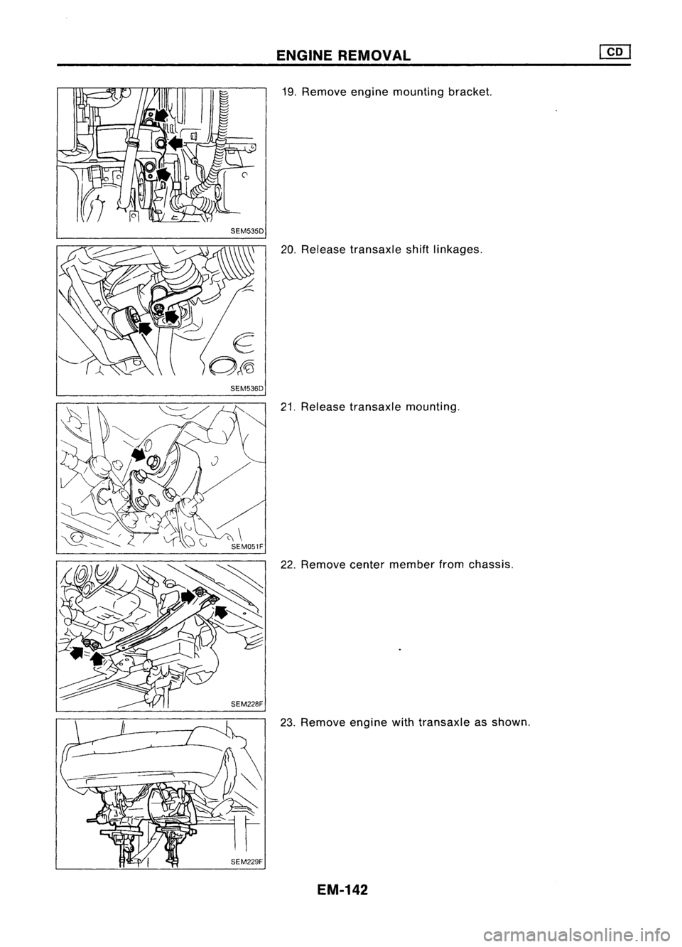
SEM535D
SEM536D ENGINE
REMOVAL
19. Remove enginemounting bracket.
20. Release transaxle shiftlinkages.
21. Release transaxle mounting.
22. Remove centermember fromchassis.
23. Remove enginewithtransaxle asshown.
EM-142
Page 1322 of 1701
![NISSAN ALMERA N15 1995 Service Manual CYLINDERBLOCK
•
l(]~
83-93
(8.5 -9.5
61 -
69)
~
~ :N.m (kg-m, ft-Ib)
f] :
Lubricate withnewengine oil.
(]
~76-78 (7.8 -8.0, 56-58)
@f]-
o
o
@~~ ~
! ~
l"J
R,t" I.
"A,~mbly& NISSAN ALMERA N15 1995 Service Manual CYLINDERBLOCK
•
l(]~
83-93
(8.5 -9.5
61 -
69)
~
~ :N.m (kg-m, ft-Ib)
f] :
Lubricate withnewengine oil.
(]
~76-78 (7.8 -8.0, 56-58)
@f]-
o
o
@~~ ~
! ~
l"J
R,t" I.
"A,~mbly&](/img/5/57349/w960_57349-1321.png)
CYLINDERBLOCK
•
l(]~
83-93
(8.5 -9.5
61 -
69)
~
~ :N.m (kg-m, ft-Ib)
f] :
Lubricate withnewengine oil.
(]
~76-78 (7.8 -8.0, 56-58)
@f]-
o
o
@~~ ~
! ~
l"J
R,t" I.
"A,~mbly".
SEC.
110-120
SEM227F
CD
Piston
ring
(J)
Rear
plate
@
Main
bearing
@
Piston
@
Flywheel
@
Crankshaft
@
Piston
pin
@
Rear
oilseal
@
Main bearing
@
Connecting
rodbearing
@)
Rear oilseal retainer
@
Gusset
@
Connecting
rod
@
Gusset
@
Drain plug
@
Main
bearing cap
@
Cylinder block
@
Pilot bushing
EM-143
Page 1323 of 1701
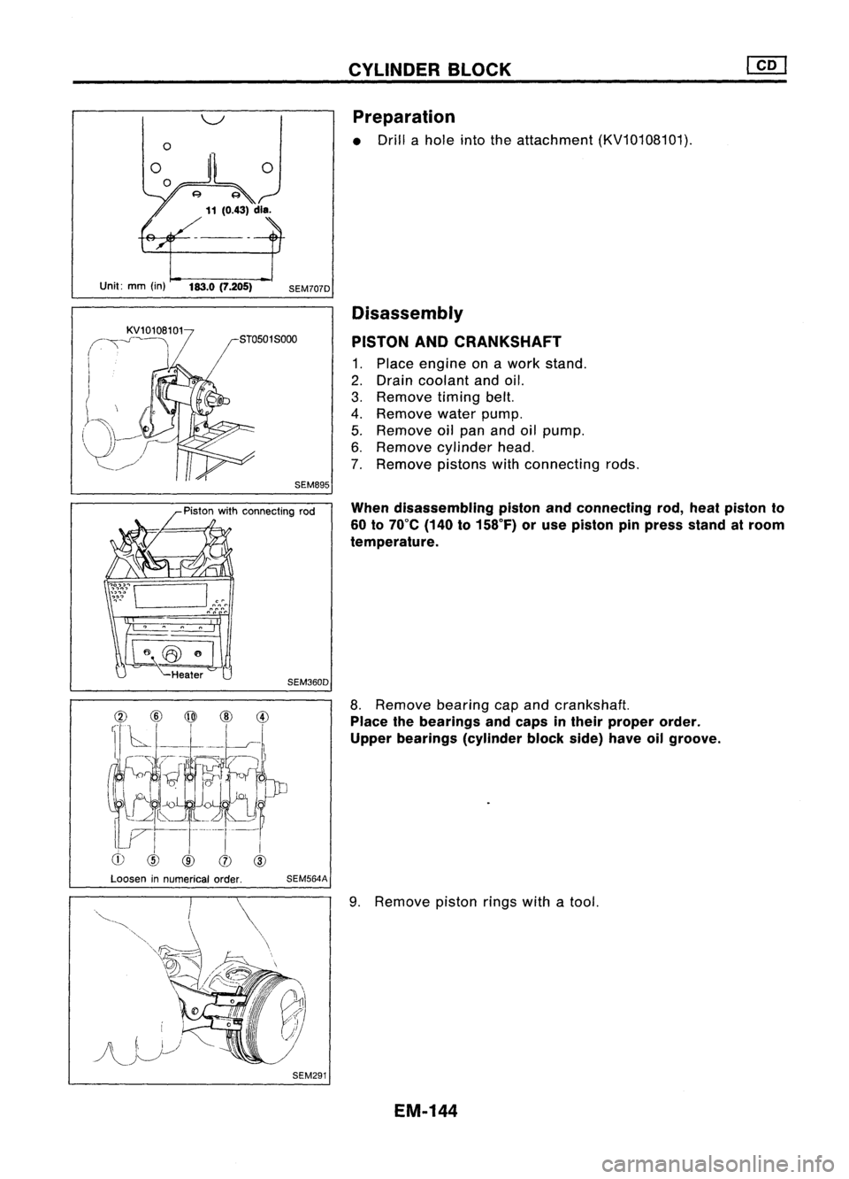
Unit:mm(in) 183.0(7.205)
SEM707DCYLINDER
BLOCK
Preparation
• Drill ahole intotheattachment (KV10108101).
Disassembly
PISTON ANDCRANKSHAFT
1. Place engine onawork stand.
2. Drain coolant andoil.
3. Remove timingbelt.
4. Remove waterpump.
5. Remove oilpan andoilpump.
6. Remove cylinder head.
7. Remove pistonswithconnecting rods.
When disassembling pistonandconnecting rod,heat piston to
60 to70°C (140to158°F) oruse piston pinpress standatroom
temperature.
Heater
SEM360D
8.Remove bearingcapand crankshaft.
Place thebearings andcaps intheir proper order.
Upper bearings (cylinderblockside)haveoilgroove.
Loosen innumerical order.
SEM564A
SEM291
9.
Remove pistonringswithatool.
EM-144
Page 1324 of 1701
CYLINDERBLOCK
Inspection
PISTON ANDPISTON PINCLEARANCE
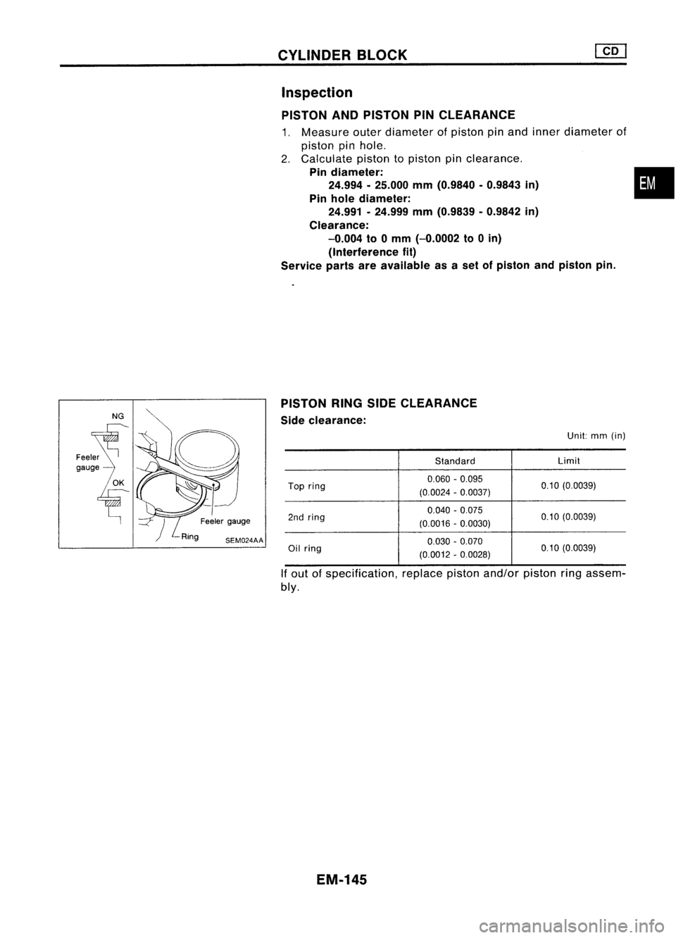
1. Measure outerdiameter ofpiston pinand inner diameter of
piston pinhole.
2. Calculate pistontopiston pinclearance.
Pin diameter: •
24.994 •25.000 mm(0.9840 -0.9843 in)
Pin hole diameter:
24.991 -24.999 mm(0.9839 -0.9842 in)
Clearance: -0.004 to0mm (-0.0002 to0in)
(Interference fit)
Service partsareavailable asaset ofpiston andpiston pin.
PISTON RINGSIDECLEARANCE
Side clearance:
Unit:mm(in)
Standard Limit
Top ring 0.060
-0.095
0.10(0.0039)
(0.0024 -0.0037)
0.040 -0.075
0.10(0.0039)
2nd ring
(0.0016-0.0030)
Oil ring 0.030
-0.070
0.10(0.0039)
(0.0012 -0.0028)
If out ofspecification, replacepistonand/or pistonringassem-
bly.
EM-145
Page 1325 of 1701
Feelergauge
SEM599A
SEM506A
Main jOUrnal~
Maintain morethan0.13mm(0.0051 In)
SEM566B CYLINDER
BLOCK
Inspection (Cont'd)
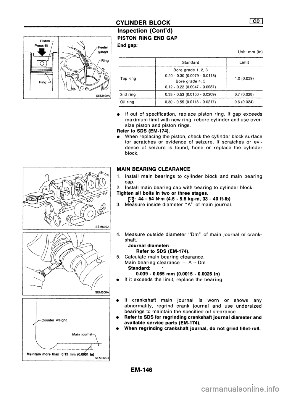
PISTON RINGENDGAP
End gap:
Unit:mm(in)
Standard Limit
Bore grade 1,2, 3
Top ring 0.20
-0.30 (0.0079 -0.0118)
1.0(0.039)
Bore grade 4,5
0.12 -0.22 (0.0047 -0.0087)
2nd ring 0.38-0.53 (0.0150 -0.0209) 0.7(0.028)
Oil ring 0.30
-0.55 (0.0118 -0.0217) 0.6(0.024)
• Ifout ofspecification, replacepistonring.Ifgap exceeds
maximum limitwithnewring, rebore cylinder anduseover-
size piston andpiston rings.
Refer toSOS (EM-174).
• When replacing thepiston, checkthecylinder blocksurface
for scratches orevidence ofseizure. Ifscratches orevi-
dence ofseizure isfound, honeorreplace thecylinder
block.
MAIN BEARING CLEARANCE
1. Install mainbearings tocylinder blockandmain bearing
cap.
2. Install mainbearing capwith bearing tocylinder block.
Tighten allbolts intwo orthree stages.
~: 44-54 N'm (4.5-5.5 kg-m, 33-40 ft-Ib)
3. Measure insidediameter" A"ofmain journal.
4. Measure outsidediameter "Om"ofmain journal ofcrank-
shaft.
Journal diameter:
Refer toSOS (EM-174).
5. Calculate mainbearing clearance.
Main bearing clearance
=
A-Om
Standard:
0.039 -0.065 mm(0.0015 -0.0026 in)
• Ifitexceeds thelimit, replace thebearing.
• Ifcrankshaft mainjournal isworn orshows any
abnormality, regrindcrankjournal anduseundersized
bearings tomaintain thespecified oilclearance.
• Refer toSOS forregrinding crankshaftjournaldiameter and
available serviceparts(EM-174).
• When regrinding crankshaftjournal,donot grind fillet-roll.
EM-146
Page 1326 of 1701
![NISSAN ALMERA N15 1995 Service Manual CYLINDERBLOCK
@[]
Inspection (Cont'd)
• Ifeither bearing, crankshaft orcylinder blockisreplaced
with anew one, select mainbearing according tothe fol-
lowing table.These numbers arepunched in NISSAN ALMERA N15 1995 Service Manual CYLINDERBLOCK
@[]
Inspection (Cont'd)
• Ifeither bearing, crankshaft orcylinder blockisreplaced
with anew one, select mainbearing according tothe fol-
lowing table.These numbers arepunched in](/img/5/57349/w960_57349-1325.png)
CYLINDERBLOCK
@[]
Inspection (Cont'd)
• Ifeither bearing, crankshaft orcylinder blockisreplaced
with anew one, select mainbearing according tothe fol-
lowing table.These numbers arepunched ineither Arabic
or Roman numerals.
Mainbearing housing gradenumber
0 1
2
Main bearing gradenumber
0 0 12
Crankshaft mainjour-
1
1
2
3
nal grade number
22
3
4
•
~NO'1 mainjournal gradenumber
NO.2 No.4
"" No. 3/ No.5
~'S"bci~
0000 "')N1
~ o.
- Counterweight
"\ /i
SEM706DAIdentification
color:
Grade 0
Grade 1
Grade 2
Grade 3
Grade 4 Yellow
Green
Brown
BlackBlue
No. 1journal gradenumber
~No.5
Q
Front
0
SEM706A
For
example:
Main journal gradenumber: 1
Crankshaft journalgradenumber: 2
Main bearing gradenumber
=
1
+
2
Main bearing thickness:
Refer toSOS (EM-175).
3
SEM507A CONNECTING
RODBEARING CLEARANCE (Bigend)
1. Install connecting rodbearing toconnecting rodand cap.
2. Install connecting rodcap with bearing toconnecting rod.
Apply oiltothe thread portion ofbolts andseating surface of
nuts.
toJ:
37-45 N'm (3.8-4.6 kg-m, 27-33 ft-Ib)
3. Measure insidediameter "C"ofbearing.
EM-147
Page 1327 of 1701
![NISSAN ALMERA N15 1995 Service Manual CYLINDERBLOCK [][]
Inspection (Cont'd)
4. Measure outsidediameter "Dp"ofcrankshaft pinjournal.
5. Calculate connecting rodbearing clearance.
Connecting rodbearing clearance
=
C-Op
Standa NISSAN ALMERA N15 1995 Service Manual CYLINDERBLOCK [][]
Inspection (Cont'd)
4. Measure outsidediameter "Dp"ofcrankshaft pinjournal.
5. Calculate connecting rodbearing clearance.
Connecting rodbearing clearance
=
C-Op
Standa](/img/5/57349/w960_57349-1326.png)
CYLINDERBLOCK [][]
Inspection (Cont'd)
4. Measure outsidediameter "Dp"ofcrankshaft pinjournal.
5. Calculate connecting rodbearing clearance.
Connecting rodbearing clearance
=
C-Op
Standard:
0.031 -0.055
mm
(0.0012 -0.0022
in)
• Ifitexceeds thelimit, replace thebearing.
• Ifcrankshaft pinjournal isworn orshows anyabnormality,
regrind crankpinand useundersized bearingstomaintain
the specified oilclearance.
• Refer toSOS forregrinding diameterofcrankshaft pinand
available serviceparts(EM-174).
• When regrinding crankshaft pin,donot grind fillet-roll.
Pin
jOUrnal~
Maintain morethan0.13mm(0.0051 in)
SEM361D
~NO' 1pin journal gradenumber
~NO' 2No.3
__ NO.4
,/
o
J
0 0 ~ NO.1
~ C,"'''ffl.;ghl
SEM705D
Selective
connecting rodbearing
• Ifeither bearings orcrankshaft arebeing replaced withnew
ones, select connecting rodbearings according tothe fol-
lowing table.Grade numbers arepunched ineither Arabic
or Roman numerals.
Crankshaftpinjournal gradenumber
0 1
2
Connecting rodbaring gradenum-
0 12
ber
Identification color
Grade 0:Black
Grade 1:Yellow
Grade 2:Blue
CONNECTING RODANDPISTON PINCLEARANCE
(Small end)
Clearance
(0-
d):
0.025 -0.044
mm
(0.0010 -0.0017
in)
• Ifclearance exceedsthespecifications, replacethebearing.
Clearance
=
0 -d
SEM575B
EM-148
Page 1328 of 1701
AB
Taper:A-B
Out-ot-round: X-y
y
SEM316A CYLINDER
BLOCK
Inspection (Cont'd)
Bearing replacement
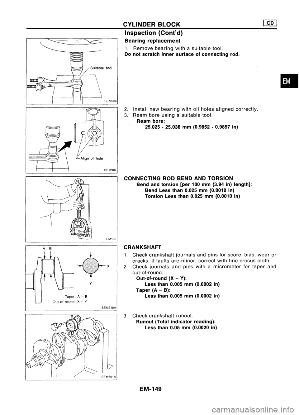
1. Remove bearingwithasuitable tool.
Do not scratch innersurface ofconnecting rod.
2. Install newbearing withoilholes aligned correctly.
3. Ream boreusing asuitable tool.
Ream bore:
25.025 -25.038 mm(0.9852 -0.9857 in)
CONNECTING RODBEND ANDTORSION
Bend andtorsion [per100mm (3.94 in)length]:
Bend Lessthan0.025 mm(0.0010 in)
Torsion Lessthan0.025 mm(0.0010 in)
CRANKSHAFT
1. Check crankshaft journalsandpins forscore, bias,wear or
cracks. Iffaults areminor, correct withfinecrocus cloth.
2. Check journals andpins withamicrometer fortaper and
out-of-round.
Out-of-round (X-V):
Less than0.005 mm(0.0002 in)
Taper (A-B):
Less than0.005 mm(0.0002 in)
•
3. Check crankshaft runout.
Runout (Totalindicator reading):
Less than0.05mm(0.0020 in)
EM-149
Page 1329 of 1701
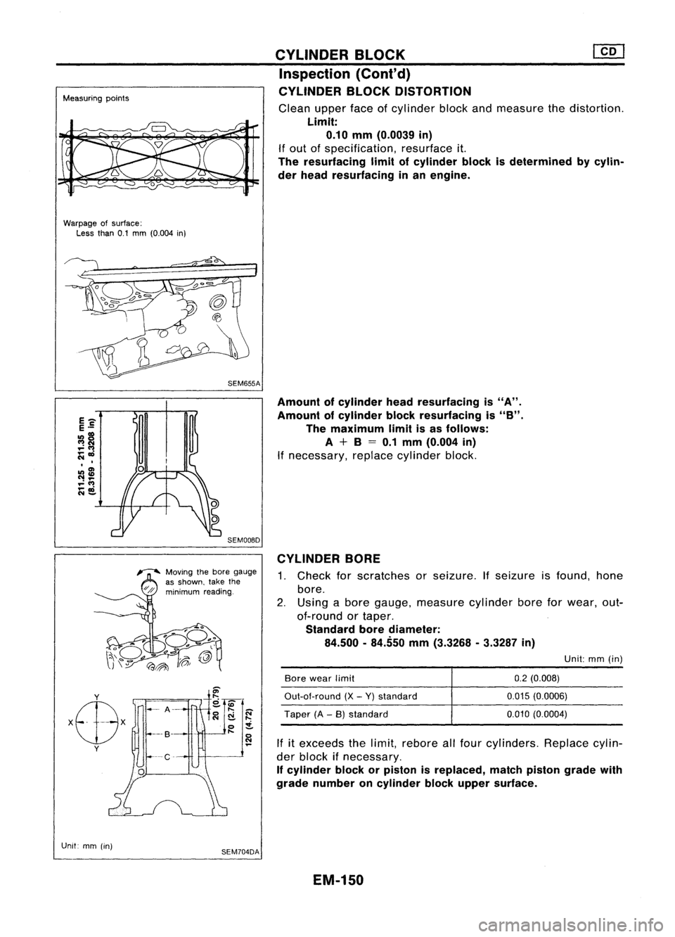
Measuringpoints
Warpage ofsurface:
Less than0.1mm (0.004 in)
SEM655ACYLINDER
BLOCK
Inspection (Cont'd)
CYLINDER BLOCKDISTORTION
Clean upperfaceofcylinder blockandmeasure thedistortion.
Limit:
0.10
mm
(0.0039
in)
If out ofspecification, resurfaceit.
The resurfacing limitofcylinder blockisdetermined bycylin-
der head resurfacing inan engine.
SEM008D
Amount
ofcylinder headresurfacing is"A".
Amount ofcylinder blockresurfacing is"B".
The maximum limitisas follows:
A + B=0.1
mm
(0.004
in)
If necessary, replacecylinder block.
~ Moving thebore gauge
as shown, takethe
//p'
minimum reading.
CYLINDER
BORE
1. Check forscratches orseizure. Ifseizure isfound, hone
bore.
2. Using abore gauge, measure cylinderboreforwear, out-
of-round ortaper.
Standard borediameter:
84.500 -84.550
mm
(3.3268 -3.3287
in)
Unit:mm(in)
If itexceeds thelimit, rebore allfour cylinders. Replacecylin-
der block ifnecessary.
If cylinder blockorpiston isreplaced, matchpiston gradewith
grade number oncylinder blockupper surface.
y
Unit mm(in)
SEM704DA
Bore
wear limit
Out-aI-round (X-Y) standard
Taper (A-B) standard
0.2
(0.008)
0.015 (0.0006)
0.010 (0.0004)
EM-150
Page 1330 of 1701
CYLINDERBLOCK
Inspection (Cont'd)
Front
0000
•
SEM1768
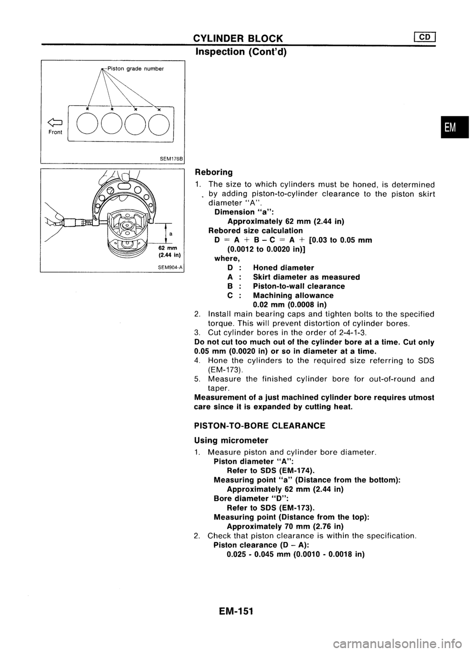
Reboring1. The size towhich cylinders mustbehoned, isdetermined
by adding piston-to-cylinder clearancetothe piston skirt
diameter" A".
Dimension "a":
Approximately 62mm (2.44 in)
Rebored sizecalculation
o
=
A
+
B-C
=
A
+
[0.03 to0.05 mm
(0.0012 to0.0020 in)]
where,
o
A B
C
Honed
diameter
Skirt diameter asmeasured
Piston-to-wall clearance
Machining allowance
0.02 mm(0.0008 in)
2. Install mainbearing capsandtighten boltstothe specified
torque. Thiswillprevent distortion ofcylinder bores.
3. Cut cylinder boresinthe order of2-4-1-3.
Do not cuttoo much outofthe cylinder boreatatime. Cutonly
0.05 mm(0.0020 in)orso indiameter atatime.
4. Hone thecylinders tothe required sizereferring toSOS
(EM-173).
5. Measure thefinished cylinder boreforout-of-round and
taper.
Measurement ofajust machined cylinderborerequires utmost
care since itis expanded bycutting heat.
62
mm
(2.44
in)
SEM904-A
PISTON-TO-BORE CLEARANCE
Using micrometer
1. Measure pistonandcylinder borediameter.
Piston diameter "A":
Refer toSDS (EM-174).
Measuring point"a"(Distance fromthebottom):
Approximately 62mm (2.44 in)
Bore diameter
"0":
Refer toSDS (EM-173).
Measuring point(Distance fromthetop):
Approximately 70mm (2.76 in)
2. Check thatpiston clearance iswithin thespecification.
Piston clearance
(0-
A):
0.025 -0.045 mm(0.0010 -0.0018 in)
EM-151