NISSAN ALMERA N15 1995 Service Manual
Manufacturer: NISSAN, Model Year: 1995, Model line: ALMERA N15, Model: NISSAN ALMERA N15 1995Pages: 1701, PDF Size: 82.27 MB
Page 1311 of 1701
![NISSAN ALMERA N15 1995 Service Manual
I
Recess
I
diameter
W: Refer toSOS.
I
SEM795A
SEMB76
SEM877
SEM635AA CYLINDER
HEAD
[£Q]
Inspection (Cont'd)
VALVE SEATREPLACEMENT
1. Bore outoldseat untilitcollapses.
Set machine depthst NISSAN ALMERA N15 1995 Service Manual
I
Recess
I
diameter
W: Refer toSOS.
I
SEM795A
SEMB76
SEM877
SEM635AA CYLINDER
HEAD
[£Q]
Inspection (Cont'd)
VALVE SEATREPLACEMENT
1. Bore outoldseat untilitcollapses.
Set machine depthst](/img/5/57349/w960_57349-1310.png)
I
Recess
I
diameter
W: Refer toSOS.
I
SEM795A
SEMB76
SEM877
SEM635AA CYLINDER
HEAD
[£Q]
Inspection (Cont'd)
VALVE SEATREPLACEMENT
1. Bore outoldseat untilitcollapses.
Set machine depthstopsothat boring cannot contact bot-
tom face ofseat recess incylinder head.
2. Ream thecylinder headrecess.
Reaming boreforservice valveseat
[Oversize 0.5mm (0.020 in)]:
Intake 41.432 -41.454 mm(1.6312 -1.6320 in)
Exhaust 35.432-35.454 mm(1.3950 -1.3958 in)
Use thevalve gUide center forreaming toensure valveseatwill
have thecorrect fit.
3. Heat cylinder headtoatemperature of150 to160°C (302to
320°F) andpress fitseat untilitseats onthe bottom.
4. Install valveseats.
When replacing valveseat,valve should bereplaced aswell.
5. Cut orgrind valve seatusing asuitable toolatthe specified
dimensions asshown inSOS (EM-172).
The cutting shouldbedone withboth hands toobtain auniform
and concentric finish.
6. Apply asmall amount offine grinding compound tothe
valve's contacting faceandputthe valve intoitsguide.
Lap valve against itsseat untilproper valveseating is
obtained.
7. Check valveseating condition.
EM-132
Page 1312 of 1701
![NISSAN ALMERA N15 1995 Service Manual
T(Margin thickness)
II
~a
.
,
I
T(Th)
D
L
CYLINDER
HEAD @Q]
Inspection (Cont'd)
VALVE DIMENSIONS
1. Check dimensions ofeach valve. Fordimensions, referto
SDS (EM-171).
2. Correct orrepla NISSAN ALMERA N15 1995 Service Manual
T(Margin thickness)
II
~a
.
,
I
T(Th)
D
L
CYLINDER
HEAD @Q]
Inspection (Cont'd)
VALVE DIMENSIONS
1. Check dimensions ofeach valve. Fordimensions, referto
SDS (EM-171).
2. Correct orrepla](/img/5/57349/w960_57349-1311.png)
T(Margin thickness)
II
~a
.
,
I
T(Th)
D
L
CYLINDER
HEAD @Q]
Inspection (Cont'd)
VALVE DIMENSIONS
1. Check dimensions ofeach valve. Fordimensions, referto
SDS (EM-171).
2. Correct orreplace anyvalve thatisfaulty .
d •
L-~
SEM188A
3.Valve faceorvalve stemendsurface shouldberefaced by
using avalve grinder.
When valveheadhasbeen worn down to0.5 mm (0.020 in)in
margin thickness, replacethevalve.
Grinding allowance torvalve stemtipis0.5 mm (0.020 in)or
less.
VALVE SPRING SQUARENESS
Check valvespring forsquareness usingasteel square andflat
surface plate.
If
spring isout ofsquare "S"more thanspecified limit,replace
with newone.
Out-at-square: OuterLess than2.1mm (0.083 in)
Inner less than1.9mm (0.075 in)
•
SEM333
VALVE SPRING PRESSURE LOAD
Measure thefree length andthetension ofeach spring. Ifthe
measured valueexceeds thespecified limit,replace spring.
Refer toSDS (EM-172).
EM113 HYDRAULIC VALVELIFTER
1. Check contact andsliding surfaces forwear orscratches .
SEM7238 EM-133
Page 1313 of 1701
SEM724B
SEM720B
WKOO"'P;O
Notch
~~~ SEM721BCYLINDER
HEAD
Inspection (Cont'd)
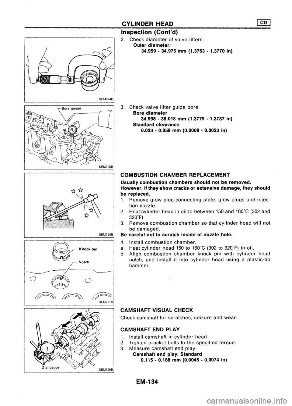
2. Check diameter ofvalve lifters.
Outer diameter:
34.959 -34.975 mm(1.3763 -1.3770 in)
3. Check valvelifterguide bore.
Bore diameter
34.998 -35.018 mm(1.3779 -1.3787 in)
Standard clearance
0.023 -0.059 mm(O.0009 -0.0023 in)
COMBUSTION CHAMBERREPLACEMENT
Usually combustion chambersshouldnotberemoved.
However, ifthey show cracks orextensive damage,theyshould
be replaced.
1. Remove glowplugconnecting plate,glowplugs andinjec-
tion nozzle.
2. Heat cylinder headinoil tobetween 150and 160°C (302and
320°F).
3. Remove combustion chambersothat cylinder headwillnot
be damaged.
Be careful nottoscratch insideofnozzle hole.
4. Install combustion chamber.
a. Heat cylinder head150to160°C (302to320°F) inoil.
b. Align combustion chamberknockpinwith cylinder head
notch, andinstall itinto cylinder headusing aplastic-tip
hammer.
CAMSHAFT VISUALCHECK
Check camshaft forscratches, seizureandwear.
CAMSHAFT ENDPLAY
1. Install camshaft incylinder head.
2. Tighten bracketboltstothe specified torque.
3. Measure camshaft endplay.
Camshaft endplay: Standard
0.115 -0.188 mm(O.0045 -0.0074 in)
EM-134
Page 1314 of 1701
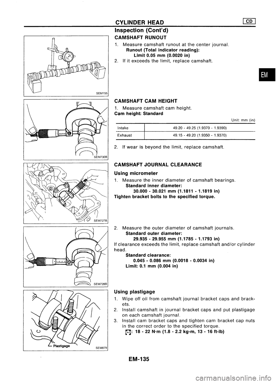
CAMSHAFTCAMHEIGHT
1. Measure camshaft camheight.
Cam height: Standard
Using micrometer
1. Measure theinner diameter ofcamshaft bearings.
Standard innerdiameter:
30.000 -30.021 mm(1.1811 -1.1819 in)
Tighten bracketboltstothe specified torque.
2. Measure theouter diameter ofcamshaft journals.
Standard outerdiameter:
29.935 -29.955 mm(1.1785 -1.1793 in)
If clearance exceedsthelimit, replace camshaft and/orcylinder
head.
Standard clearance:
0.045 -0.086 mm(0.0018 -0.0034 in)
Limit: 0.1mm (0.004 in)
•
Unit: mm(in)
49.20 -4925 (1.9370 -1.9390)
49.15 -49.20 (1.9350 -1.9370)
Intake
Exhaust
2. Ifwear isbeyond thelimit, replace camshaft.
CYLINDER
HEAD
Inspection (Cont'd)
CAMSHAFT RUNOUT
1. Measure camshaft runoutatthe center journal.
Runout (Totalindicator reading):
Limit 0.05mm(0.0020 in)
2. Ifitexceeds thelimit, replace camshaft.
CAMSHAFT JOURNALCLEARANCE
Using plastigage
1. Wipe offoilfrom camshaft journalbracket capsandbrack-
ets.
2. Install camshaft injournal bracket capsandputplastigage
on each camshaft journal.
3. Install cambracket capsandtighten cambracket capnuts
in the correct ordertothe specified torque.
~: 18-22 N'm (1.8-2.2 kg-m, 13-16 ft-Ib)
EM-135
Page 1315 of 1701
![NISSAN ALMERA N15 1995 Service Manual SEM202
SEM731BA
Grade number
Tightening sequence
r
1
@@
~.~.~
o
,..0
W
@
@ @
Facing frontofengine
(position 2)
SEM528DCYLINDER
HEAD
[£Q]
Inspection {Cont'd)
4. Remove cambracket capsan NISSAN ALMERA N15 1995 Service Manual SEM202
SEM731BA
Grade number
Tightening sequence
r
1
@@
~.~.~
o
,..0
W
@
@ @
Facing frontofengine
(position 2)
SEM528DCYLINDER
HEAD
[£Q]
Inspection {Cont'd)
4. Remove cambracket capsan](/img/5/57349/w960_57349-1314.png)
SEM202
SEM731BA
Grade number
Tightening sequence
r
1
@@
~.~.~
o
,..0
W
@
@ @
Facing frontofengine
(position 2)
SEM528DCYLINDER
HEAD
[£Q]
Inspection {Cont'd)
4. Remove cambracket capsandmeasure maximum widthof
plastigage. Camshaft bearingclearance:
Limit
0.1 mm (0.004 in)
5. Ifclearance appearstoexceed thelimit, replace camshaft
or cylinder head.
• Which partstobe replaced shouldbedecided uponafter
measuring thediameters ofthe parts concerned.
Assembly
1. Install valvecomponent parts.
Install valvespring withitsnarrow pitchsidetoward cylinder
head side.
• Always installnewvalve oilseals.
Refer tooil seal replacement.
• Before installing oilseal, install valve-spring seat.
• When installing valve,applyengine oilonthe valve stem
and lipofvalve oilseal.
• Check whether thevalve faceisfree from foreign matter.
• Install valvespring retainers onthe intake sideandvalve
rotators onthe exhaust side.
• Valve rotators cannotbedisassembled.
2. Install camshaft andbrackets andtighten bracket nutstothe
specified torqueintwo orthree stages.
Camshaft-bracket nuts:
~: 18-22 N'm (1.8-2.2 kg-m, 13-16 ft-Ib)
• Tighten bracketfromcenter tooutside.
• Apply sealant tobrackets No.1and No.5.
• When installing "brackets, setcamshaft sothat thepinof
camshaft fronthead isuppermost.
• Install newcamshaft oilseals.
Refer tooil seal replacement.
17.5 (0.689)
o
o
13.0
(0.512)
NO.1 journal bracket No.5journal bracket
Unit: mm(in)
SEM676D
EM-136
Page 1316 of 1701
Cylinderheadbolt
N.m (kg-m, ft-Ib)
83 -93
(8.5 -9.5,
(Iii(~)
61.2 -68.6)
39 (4.0, 29)
o
N.m (0kg-m, 0ft-Ib)
SEM673DA
SEM678D CYLINDER
HEAD
Installation
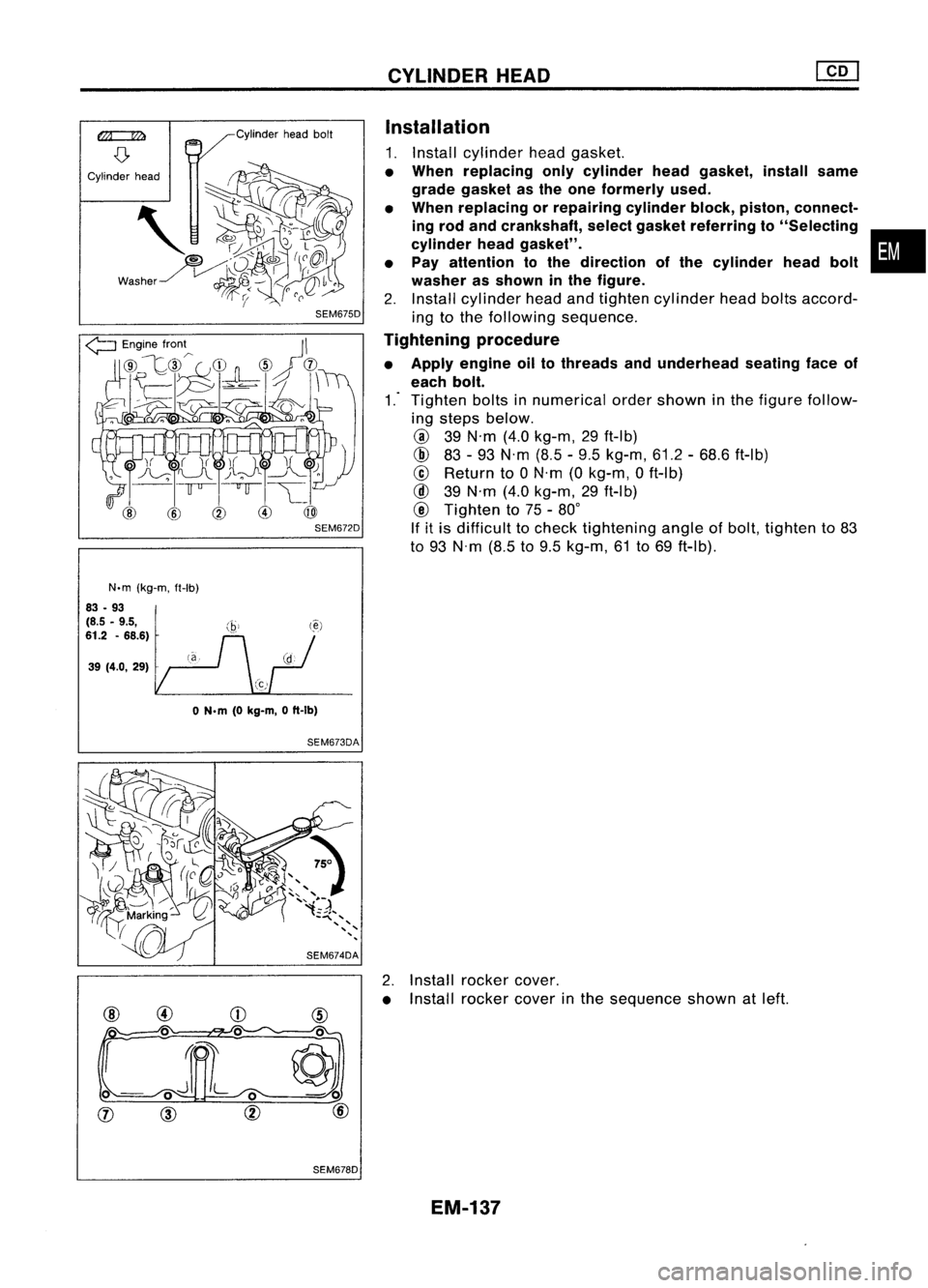
1. Install cylinder headgasket.
• When replacing onlycylinder headgasket, installsame
grade gasket asthe one formerly used.
• When replacing orrepairing cylinderblock,piston, connect-
ing rod and crankshaft, selectgasket referring to"Selecting •
cylinder headgasket".
• Pay attention tothe direction ofthe cylinder headbolt
washer asshown inthe figure.
2. Install cylinder headandtighten cylinder headboltsaccord-
ing tothe following sequence.
Tightening procedure
• Apply engine oiltothreads andunderhead seatingfaceof
each bolt.
1.-
Tighten boltsinnumerical ordershown inthe figure follow-
ing steps below.
@
39N'm (4.0kg-m, 29ft-Ib)
@
83-93 N'm (8.5-9.5 kg-m, 61.2-68.6 ft-Ib)
@
Return to0N'm (0kg-m, 0ft-Ib)
@
39N'm (4.0kg-m, 29ft-Ib)
@
Tighten to75 -80°
If itis difficult tocheck tightening angleofbolt, tighten to83
to 93 N'm (8.5to9.5 kg-m, 61to69 ft-Ib).
2. Install rocker cover.
• Install rocker coverinthe sequence shownatleft.
EM-137
Page 1317 of 1701
![NISSAN ALMERA N15 1995 Service Manual
Unit:mm(in)
SEM529DCYLINDER
HEAD
@[]
Installation (Cont'd)
• Apply sealing compound (THREE-BOND No.10or equiva-
lent) toboth ends ofbrackets No.1andNo.5.
Selecting cylinderheadgasket
When NISSAN ALMERA N15 1995 Service Manual
Unit:mm(in)
SEM529DCYLINDER
HEAD
@[]
Installation (Cont'd)
• Apply sealing compound (THREE-BOND No.10or equiva-
lent) toboth ends ofbrackets No.1andNo.5.
Selecting cylinderheadgasket
When](/img/5/57349/w960_57349-1316.png)
Unit:mm(in)
SEM529DCYLINDER
HEAD
@[]
Installation (Cont'd)
• Apply sealing compound (THREE-BOND No.10or equiva-
lent) toboth ends ofbrackets No.1andNo.5.
Selecting cylinderheadgasket
When replacing onlycylinder headgasket, installthesame
grade (Number ofnotches) gasketasthe one formerly used.
Step 1
Measure projection ofpiston tocylinder headsurface.
a) Set dial gauge andneedle oncylinder blockandadjust dial
gauge tozero.
b) Set dial gauge needle atmeasuring pointonpiston, taking
care nottodisturb itszero setting.
c) Rotate crankshaft aroundthetopdead center position.
d) Read andwrite down themaximum value.
e) Reset dialgauge oncylinder blockandconfirm thatzero
setting hasnotbeen disturbed duringmeasurement.
f) Repeat stepsbthrough dfor allmeasuring pointsasillus-
trated andforeach cylinder.
• Besure thatpiston whose projection isbeing measured is
at its TDC.
Step 2
Calculate theaverage valueofmeasurements takenforeach
piston.
Step 3
Calculate theaverage valueofmeasurements forallpistons
from thevalues obtained fromstep2.
Step 4
Round offthe value obtained.
Step 5
Determine requiredthickness ofgasket, referring tochart
A.
EM-138
Page 1318 of 1701
![NISSAN ALMERA N15 1995 Service Manual
SEM530D
CYLINDER
HEAD
[£[]
Installation (Cont'd)
Relation between pistonaverage projection andcylinder head
gasket (ChartA)
Average valueof
Gasketthickness Grade
piston projec-
mm(in) (Number NISSAN ALMERA N15 1995 Service Manual
SEM530D
CYLINDER
HEAD
[£[]
Installation (Cont'd)
Relation between pistonaverage projection andcylinder head
gasket (ChartA)
Average valueof
Gasketthickness Grade
piston projec-
mm(in) (Number](/img/5/57349/w960_57349-1317.png)
SEM530D
CYLINDER
HEAD
[£[]
Installation (Cont'd)
Relation between pistonaverage projection andcylinder head
gasket (ChartA)
Average valueof
Gasketthickness Grade
piston projec-
mm(in) (Number
of
tions notches)
mm (in)
Newparts
Inassembly
1.25 (0.0492) 1.1~gg~
0
Less than
0.505 (0.0433
~ggg;~)
(0.0199) 1.15_+gg~
1.30 (0.0512)
(0.0453~ggg~g) 1
0.505 -0.555
1.35(0.0931) 1.20_+gg~
(0.0199 -0.0219)
(0.0472~ggg~g ) 2
.
Over
0.555 1.25_+gg~
(0.0219) 1.40
(0.0551)
(0.0492~ggg~g ) 3
Step 6
Check ifthe average valueofeach projection obtainedfrom
step 2is larger thanthemax. value ofthe standard projection
(of selected gasket)incremented by0.05 mm(0.0020 in).
If so, use gasket thatis1grade thicker. Ifnot so,use gasket as
selected instep 4.
•
Example
Unit:mm(in)
Step Cylinder
No.
1 2 34
Item
M1M2M3 M4M1 M2M3 M4M1
M2M3
.
M4 M1
M2M3M4
1. Measured
value 0.53
0.560.53 0.560.59 0.55 0.59
0550.53 0.580.57
0.54
0.58 0.51052 0.57
(0.0209) (0.0220)(0.0209)(0.0220)
(0.0232)(0.0217)
(0.0232)(0.0217)(0.0209)(0.0228)(0.0224)(0.0213)(0.0228) (0.0201)(0.0205) (0.0224)
Average 0.545 0.57
0.555 0.545
2 value
ofeach
(0.0215) (0.0224)-(0.0219)
(0.0215)
piston
Average
3 value
ofall 055375(0.02180)
pistons
4. Round
off
0.554(0.0218)'1
value
Determined
5. gasket
thick-
120(0.0472) (Grade8)
ness (Tempo-
rarily)
X: Maximum valueofstandard projection ofselected gasket...0.555 (0.0219) (inchart A)
+
0.05 (0.0020)
=
0.605 (0.0238)
6. Y:Maximum valueinstep 2
=
0.57 (0.0224)
The relationship betweenXand Yis "X
>
Y.... 2
Determined
7. gasket thick- 1.20(0.0472) (Grade8)'2
ness (Finally)
*1: IIthe average value
01
projections lorallpistons is,lor example, 0.553(7)5,as shown inthe table above, itshould berounded oilasfol-
lows:
II the digit inthe forth decimal place(which isenclosed byacircle inthis case) issmaller than5,the average valueshould beregarded
as 0.553 mm(0.0218 in);ilitis larger than5,the average valueshould beregarded as0.554 mm(0.0218 in).
*2: IIX
<
Y, then thethicker gradeCgasket mustbeused.
EM-139
Page 1319 of 1701
SEC.112 ENGINE
REMOVAL
~~ 44.54(4.5.5.5,33 -40)
~44 .54 (4.5 .5.5, 33.40) ~~
~ 44•54 (4.5 .5.5, 33•40)"\ ~
-~1J.
~1
~~' ~64.74,
_' 2
(6.5.7.5, / \
~ 47.54),/'
rJ44. 54(4.5.5.5,33 -40) ~\
'" ~~~44.54 \....
.- ,9
(4.5.5.5,
ttJJ 44-54 (4.5 •5.5, 33-40)
7
ttJJ64.75 ------~
@--."
('.5•7.5, 4~' \
y~
~~.~~ ~~f;fi\
~~~'~i':-l~"
k(j' --.
II!~o' ~
/'Oolk..,
ttJJ64.75 (6.5•7.5, 47•54) ~
~'o
@\
8,.'~
~- I
2
rJ64. 75(6.5 .7.5,47.54)..1"""-../
~2ft -."~
°
>
~44. 54
~@
ttJJ44.54(4.5 -5.5, 33. 40)
j~~~1 ~-/.~/
(4.5 -5.5, 33•40)
ti ~~
44•54
~'@
A
5~'
!-'~
~35'-4~.)5'~ ~/
,0
7
~ I~. '
.Vi
rJ44.54(4.5.5.5,33.40)
~ ~l
ttJJ44•54 (4.5 •5.5, 33•40)
~ 'l
o.o~
I...",;S'"
1.
..J'-;:7o
6
ttJJ44.54 (4.5 •5.5, 33•40)
~l \
'LrJ 44•54 (4.5 -5.5, 33•40)
ttJJ 44.54 (4.5 .5_5, 33.40)
rJ
N.m(kg-m. ft-Ibl
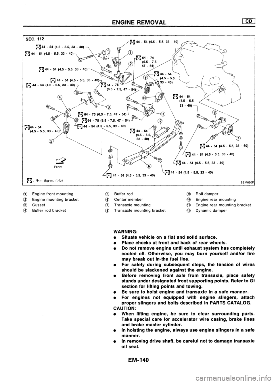
G)
Engine frontmounting
@
Engine mounting bracket
@
Gusset
@
Buffer rodbracket
@
Buffer rod
@
Center member
(J)
Transaxle mounting
@
Transaxle mountingbracket
SEM050F
@
Rolldamper
@)
Engine rearmounting
@
Engine rearmounting bracket
@
Dynamic damper
WARNING:
• Situate vehicle onaflat and solid surface.
• Place chocks atfront andback ofrear wheels.
• Donot remove engineuntilexhaust systemhascompletely
cooled off.Otherwise, youmay burn yourself and/orfire
may break outin.the fuel line.
• For safety during subsequent steps,thetension ofwires
should beslackened againsttheengine.
• Before removing frontaxlefrom transaxle, placesafety
stands underdesignated frontsupporting points.RefertoGI
section forlifting points andtowing.
• Besure tohoist engine andtransaxle inasafe manner.
• For engines notequipped withengine slingers, attach
proper slingers andbolts described inPARTS CATALOG.
CAUTION:
• When liftingengine, besure toclear surrounding parts.
Take special careforaccelerator wirecasing, brakelines
and brake master cylinder.
• Inhoisting theengine, alwaysuseengine slingers inasafe
manner.
• Inremoving driveshaft, becareful nottodamage transaxle
oil seal.
EM-140
Page 1320 of 1701
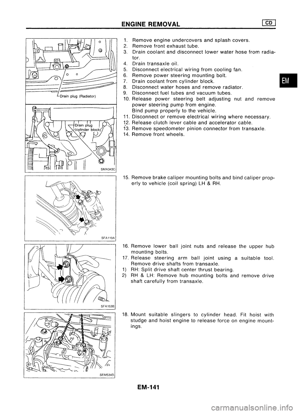
Drainplug(Radiator)
SFA110A
SFA 1538
SEM534D ENGINE
REMOVAL
1. Remove engineundercovers andsplash covers.
2. Remove frontexhaust tube.
3. Drain coolant anddisconnect lowerwater hosefromradia-
tor.
4. Drain transaxle oil.
5. Disconnect electricalwiringfromcooling fan.
6. Remove powersteering mounting bolt. •
7. Drain coolant fromcylinder block.
8. Disconnect waterhoses andremove radiator.
9. Disconnect fueltubes andvacuum tubes.
10. Release powersteering beltadjusting nutand remove
power steering pumpfromengine.
Bind pump properly tothe vehicle.
11. Disconnect orremove electrical wiringwhere necessary.
12. Release clutchlevercable andaccelerator cable.
13. Remove speedometer pinionconnector fromtransaxle.
14. Remove frontwheels.
15. Remove brakecaliper mounting boltsandbind caliper prop-
erly tovehicle (coilspring) LH
&
RH.
16. Remove lowerballjoint nutsandrelease theupper hub
mounting bolts.
17. Release steering armballjoint using asuitable tool.
Remove driveshafts fromtransaxle.
1) RH: Split drive shaftcenter thrustbearing.
2) RH
&
LH: Remove hubmounting boltsandremove drive
shaft carefully fromtransaxle.
18. Mount suitable slingers tocylinder head.Fithoist with
studge andhoist engine torelease forceonengine mount-
ings.
EM-141