NISSAN ALMERA N15 1995 Service Manual
Manufacturer: NISSAN, Model Year: 1995, Model line: ALMERA N15, Model: NISSAN ALMERA N15 1995Pages: 1701, PDF Size: 82.27 MB
Page 1281 of 1701
SEM141FA
jPiSIOn healer
SEM877S CYLINDER
BLOCK
CAUTION:
• When installing slidingparts(bearings, pistons,etc.),apply
new engine oiltothe sliding surfaces.
• Place removed partssuchasbearings andbearing capsin
their proper orderanddirection.
• Apply newengine oiltobolt thread andseat surfaces when
tightening thefollowing: Connecting rodbolts andmain
bearing capbolts.
• Donot allow anymagnetic materials tocontact thering gear
teeth offlywheel/drive plate.
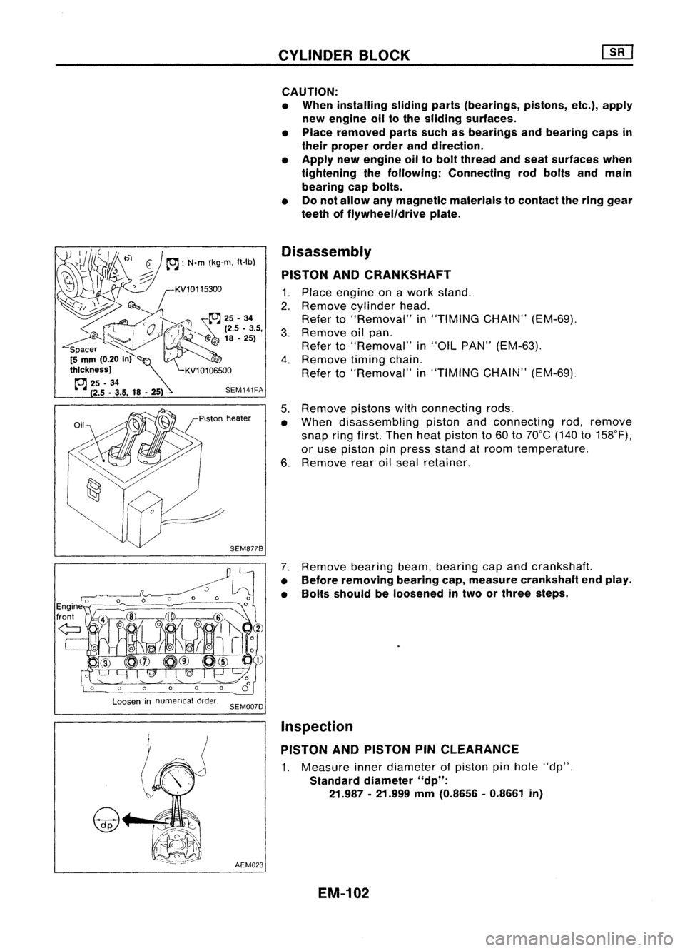
Disassembly
PISTON ANDCRANKSHAFT
1. Place engine onawork stand.
2. Remove cylinder head.
Refer to"Removal" in"TIMING CHAIN"(EM-69).
3. Remove oilpan.
Refer to"Removal" in"OIL PAN" (EM-63).
4. Remove timingchain.
Refer to"Removal" in"TIMING CHAIN"(EM-69).
5. Remove pistonswithconnecting rods.
• When disassembling pistonandconnecting rod,remove
snap ringfirst. Then heatpiston to60 to70°C (140to158°F),
or use piston pinpress stand atroom temperature.
6. Remove rearoilseal retainer.
7. Remove bearingbeam,bearing capand crankshaft.
• Before removing bearingcap,measure crankshaft endplay.
• Bolts should beloosened intwo orthree steps.
Loosen innumerical order.
SEM007D
AEM023
Inspection
PISTON ANDPISTON PINCLEARANCE
1. Measure innerdiameter ofpiston pinhole "dp".
Standard diameter"dp":
21.987 -21.999
mm
(0.8656 -0.8661
in)
EM-102
Page 1282 of 1701
![NISSAN ALMERA N15 1995 Service Manual
Micrometer
AEM024
NG
F •• ~K
gauge
OK
~-
Feelergauge
SEM024AA
P;""A
pre.it
Feeler
~
gauge
Ring
Measuring point
SEM822B
Bend
SEM003FCYLINDER
BLOCK [][]
Inspection (Cont'd)
NISSAN ALMERA N15 1995 Service Manual
Micrometer
AEM024
NG
F •• ~K
gauge
OK
~-
Feelergauge
SEM024AA
P;""A
pre.it
Feeler
~
gauge
Ring
Measuring point
SEM822B
Bend
SEM003FCYLINDER
BLOCK [][]
Inspection (Cont'd)](/img/5/57349/w960_57349-1281.png)
Micrometer
AEM024
NG
F •• ~K
gauge
OK
~-
Feelergauge
SEM024AA
P;""A
pre.it
Feeler
~
gauge
Ring
Measuring point
SEM822B
Bend
SEM003FCYLINDER
BLOCK [][]
Inspection (Cont'd)
2. Measure outerdiameter ofpiston pin"Dp".
Standard diameter "Op":
21.989 -22.001 mm(0.8657 -0.8662 in)
3. Calculate pistonpinclearance.
dp -Op
=
-0.004 to0mm (-0.0002 to0in)
If itexceeds theabove value, replace pistonassembly with
pin.
PISTON RINGSIDECLEARANCE
Side clearance:
Top ring 0.045-0.080 mm(0.0018 -0.0031 in)
2nd ring 0.030-0.065 (0.0012 -0.0026 in)
Max. limitofside clearance:
0.2 mm (0.008 in)
If out ofspecification, replacepistonand/or pistonringassem-
bly.
PISTON RINGENDGAP
End gap:
Top ring 0.20-0.30 mm(0.0079 -0.0118 in)
2nd ring 0.35-0.50 mm(0.0138 -0.0197 in)
Oil ring 0.20-0.60 mm(0.0079 -0.0236 in)
Max. limitofring gap:
1.0 mm (0.039 in)
If out ofspecification, replacepistonring.Ifgap stillexceeds
the limit even withanew ring, dothe following. Reborecylin-
der and useover-sized pistonandpiston rings.
Refer to50S (EM-168).
• When replacing thepiston, inspect cylinder blocksurface
for scratches orseizure. Ifscratches orseizure arefound,
hone orreplace thecylinder block.
CONNECTING RODBEND ANDTORSION
Bend:
Limit 0.15mm(0.0059 in)
per 100 mm (3.94 in)length
Torsion: Limit 0.30mm(0.0118 in)
per 100 mm (3.94 in)length
If itexceeds thelimit, replace connecting rodassembly.
EM-103
•
Page 1283 of 1701
SEM123CCYLINDER
BLOCK ~
Inspection (Cont'd)
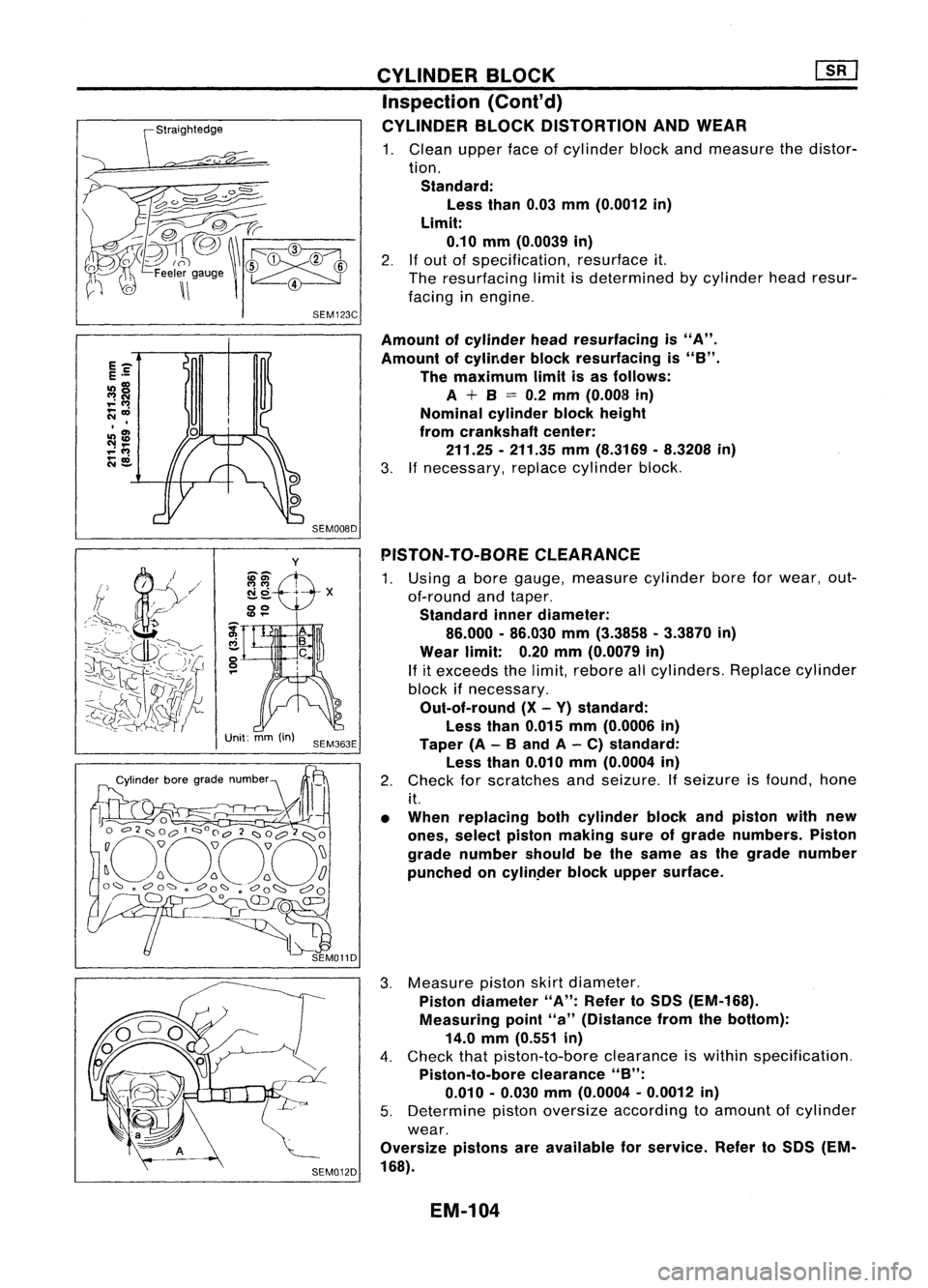
CYLINDER BLOCKDISTORTION ANDWEAR
1. Clean upperfaceofcylinder blockandmeasure thedistor-
tion. Standard: Less than0.03mm(0.0012 in)
Limit: 0.10 mm(0.0039 in)
2.
If
out ofspecification, resurfaceit.
The resurfacing limitisdetermined bycylinder headresur-
facing inengine.
SEM008D
Amount
ofcylinder headresurfacing is"A".
Amount ofcylinder blockresurfacing is
"8".
The maximum limitisas follows:
A
+
8
=
0.2 mm (0.008 in)
Nominal cylinderblockheight
from crankshaft center:
211.25 -211.35 mm(8.3169 -8.3208 in)
3. Ifnecessary, replacecylinder block.
y
ii-El)'
N 0+ -X
--
00
Unit: mm(in)
SEM363E PISTON-
TO-BORE CLEARANCE
1. Using abore gauge, measure cylinderboreforwear, out-
of-round andtaper.
Standard innerdiameter:
86.000 -86.030 mm(3.3858 -3.3870 in)
Wear limit: 0.20mm(0.0079 in)
If
itexceeds thelimit, rebore allcylinders. Replacecylinder
block ifnecessary.
Out-of-round (X-Y) standard:
Less than0.015 mm(0.0006 in)
Taper (A-
8
and A-C) standard:
Less than0.010 mm(0.0004 in)
2. Check forscratches andseizure. Ifseizure isfound. hone
it.
• When replacing bothcylinder blockandpiston withnew
ones, select piston making sureofgrade numbers. Piston
grade number shouldbethe same asthe grade number
punched oncylinper blockupper surface.
3. Measure pistonskirtdiameter.
Piston diameter "A":Refer toSDS (EM-168).
Measuring point"a"(Distance fromthebottom):
14.0 mm(0.551 in)
4. Check thatpiston-to-bore clearanceiswithin specification.
Piston-to-bore clearance"B":
0.010 -0.030 mm(0.0004 -0.0012 in)
5. Determine pistonoversize according toamount ofcylinder
wear.
Oversize pistonsareavailable forservice. RefertoSDS (EM-
168).
EM-104
Page 1284 of 1701
AB
Taper:A-B
Out-at-round: X-
y
y
SEM316A CYLINDER
BLOCK ~
Inspection (Cont'd)
6. Cylinder boresizeisdetermined byadding piston-to-bore
clearance topiston diameter "A".
Rebored sizecalculation:
D=A+B-C where,
D: Bored diameter
A: Piston diameter asmeasured •
B: Piston-to-bore clearance
C: Honing allowance 0.02mm(0.0008 in)
7. Install mainbearing caps,andtighten tothe specified
torque.
• Otherwise, cylinderboresmaybedistorted infinal assem-
bly.
8. Cut cylinder bores.
• When anycylinder needsboring, allother cylinders must
also bebored.
• Donot cuttoo much outofcylinder boreatatime. Cutonly
0.05 mm(0.0020 in)orso indiameter atatime.
9. Hone cylinders toobtain specified piston-to-bore clearance.
10. Measure finishedcylinder boreforout-of-round andtaper.
• Measurement shouldbedone aftercylinder borecools
down.
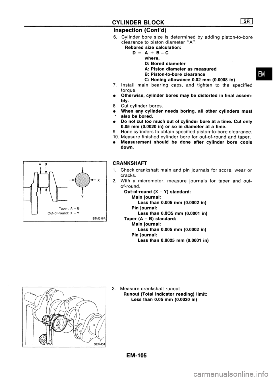
CRANKSHAFT
1. Check crankshaft mainandpinjournals forscore, wearor
cracks.
2. With amicrometer, measurejournalsfortaper andout-
of-round.
Out-of-round (X-Y) standard:
Main journal:
Less than0.005 mm(0.0002 in)
Pin journal:
Less than0.005 mm(0.0001 in)
Taper (A-B) standard:
Main journal:
Less than0.005 mm(0.0002 in)
Pin journal:
Less than0.0025 mm(0.0001 in)
3. Measure crankshaft runout.
Runout (Totalindicator reading)limit:
Less than0.05mm(0.0020 in)
EM-105
Page 1285 of 1701
#5
#4 ~
~i1
hole #3~~ \)
#2 ~~,
#1~~~ ~~
12 ~~
Engine front~
SEM685D
SEM964
SEM313D CYLINDER
BLOCK
Inspection (Cont'd)
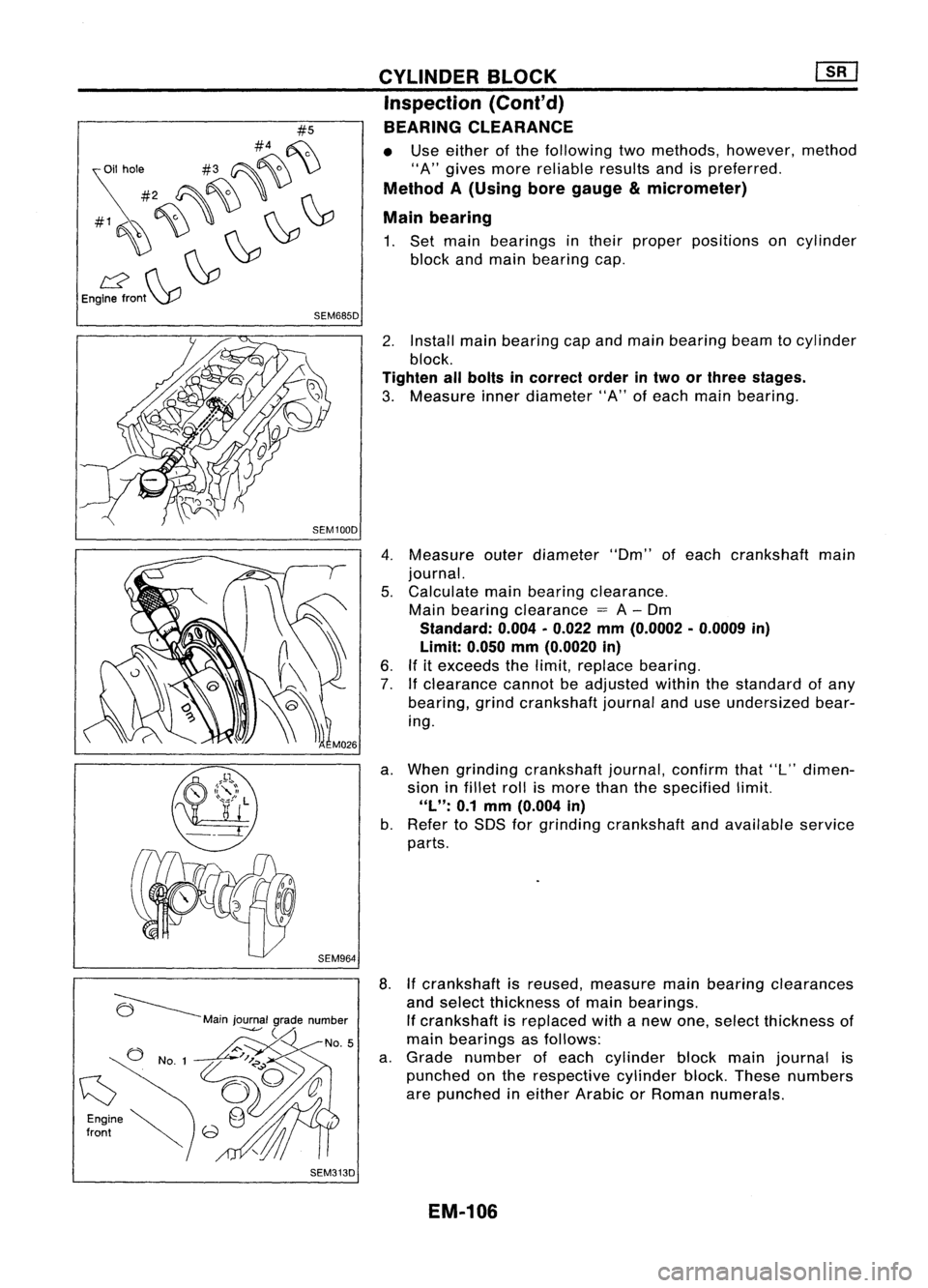
BEARING CLEARANCE
• Use either ofthe following twomethods, however, method
"A" gives morereliable resultsandispreferred.
Method A(Using boregauge
&
micrometer)
Main bearing
1. Set main bearings intheir proper positions oncylinder
block andmain bearing cap.
2. Install mainbearing capand main bearing beamtocylinder
block.
Tighten allbolts incorrect orderintwo orthree stages.
3. Measure innerdiameter "A"ofeach main bearing.
4. Measure outerdiameter "Om"ofeach crankshaft main
journal.
5. Calculate mainbearing clearance.
Main bearing clearance
=
A-Om
Standard: 0.004•0.022 mm(0.0002 •0.0009 in)
Limit: 0.050mm(0.0020 in)
6. Ifitexceeds thelimit, replace bearing.
7. Ifclearance cannotbeadjusted withinthestandard ofany
bearing, grindcrankshaft journalanduseundersized bear-
ing.
a. When grinding crankshaft journal,confirmthat"L"dimen-
sion infillet rollismore thanthespecified limit.
"L":
0.1mm (0.004 in)
b. Refer toSOS forgrinding crankshaft andavailable service
parts.
8. Ifcrankshaft isreused, measure mainbearing clearances
and select thickness ofmain bearings.
If crankshaft isreplaced withanew one, select thickness of
main bearings asfollows:
a. Grade number ofeach cylinder blockmainjournal is
punched onthe respective cylinderblock.These numbers
are punched ineither Arabic orRoman numerals.
EM-106
Page 1286 of 1701
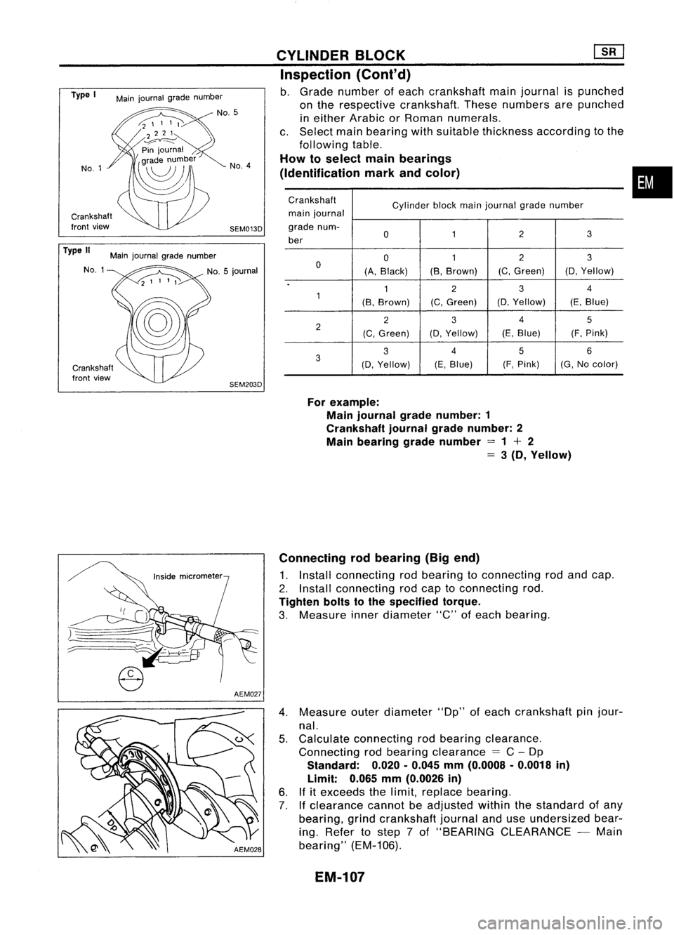
Crankshaft
front view
Crankshaft
front view
•
Crankshaft
Cylinderblockmainjournal gradenumber
main journal
grade num-
0 12
3
ber
012
3
0
(A,Black) (B,
Brown) (C,
Green) (0,Yellow)
.
12
3
4
1
(B,Brown) (C,Green) (0,
Yellow) (E,Blue)
2
3
4
5
2
(C,Green) (0,
Yellow) (E,Blue) (F,Pink)
3
4
5
6
3
(0,Yellow) (E,
Blue) (F,
Pink) (G,Nocolor)
For example:
Main journal gradenumber: 1
Crankshaft journalgradenumber: 2
Main bearing gradenumber =1+ 2
=
3(D, Yellow)
CYLINDER
BLOCK ~
Inspection (Conl'd)
b. Grade number ofeach crankshaft mainjournal ispunched
on the respective crankshaft. Thesenumbers arepunched
in either Arabic orRoman numerals.
c. Select mainbearing withsuitable thickness according tothe
following table.
How toselect mainbearings
(Identification markandcolor)
SEM013D No.
4
SEM203D
Main
journal gradenumber
No.5
Main journal gradenumber
NO.1
Type
I
No.1
Type II
Connectingrodbearing (Bigend)
1. Install connecting rodbearing toconnecting rodand cap.
2. Install connecting rodcap toconnecting rod.
Tighten boltstothe specified torque.
3. Measure innerdiameter "C"ofeach bearing.
4. Measure outerdiameter "Dp"ofeach crankshaft pinjour-
nal.
5. Calculate connecting rodbearing clearance.
Connecting rodbearing clearance
=
C-Dp
Standard:
0.020.0.045
mm
(0.0008 .0.0018
in)
Limit:
0.065
mm
(0.0026
in)
6. Ifitexceeds thelimit, replace bearing.
7.
If
clearance cannotbeadjusted withinthestandard ofany
bearing, grindcrankshaft journalanduseundersized bear-
ing. Refer tostep 7of "BEARING CLEARANCE -Main
bearing" (EM-106).
EM-107
Page 1287 of 1701
Connectingrodbearing grade
number
o
1
2
o
1
2
Crank
pingrade number
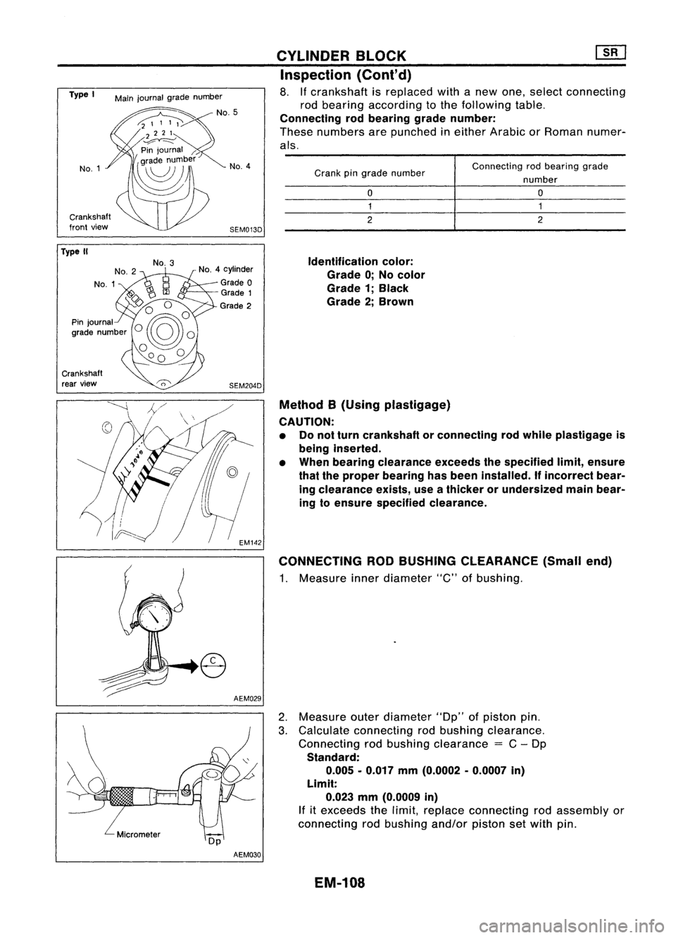
Identification color:
Grade 0;No color
Grade 1;Black
Grade 2;Brown
Method B(Using plastigage)
CAUTION: • Donot turn crankshaft orconnecting rodwhile plastigage is
being inserted.
• When bearing clearance exceedsthespecified limit,ensure
that theproper bearing hasbeen installed.
If
incorrect bear-
ing clearance exists,useathicker orundersized mainbear-
ing toensure specified clearance.
CONNECTING RODBUSHING CLEARANCE (Smallend)
1. Measure innerdiameter "C"ofbushing.
CYLINDER
BLOCK ~
Inspection (Cont'd)
8. Ifcrankshaft isreplaced withanew one, select connecting
rod bearing according tothe following table.
Connecting rodbearing gradenumber:
These numbers arepunched ineither Arabic orRoman numer-
als.
AEM029
SEM013D
No.
4
SEM204D
No.
4cylinder
Grade 0
Grade 1
Grade 2
No.
3
Main
journal gradenumber
No.1
Crankshaft
front view
Type
I
Crankshaft rear view
Type
II
2.Measure outerdiameter "Dp"ofpiston pin.
3. Calculate connecting rodbushing clearance.
Connecting rodbushing clearance
=
C-Dp
Standard: 0.005 -0.017 mm(0.0002 -0.0007 in)
Limit: 0.023 mm(0.0009 in)
If
itexceeds thelimit, replace connecting rodassembly or
connecting rodbushing and/orpistonsetwith pin.
AEM030
EM-108
Page 1288 of 1701
![NISSAN ALMERA N15 1995 Service Manual
M/T
Crankshaft
side
AIT
SEM062A
SEM163B CYLINDER
BLOCK [][]
Inspection (Conl'd)
REPLACEMENT OFCONNECTING RODBUSHING (Small
end)
1. Drive insmall endbushing untilitis flush withendsurface
of r NISSAN ALMERA N15 1995 Service Manual
M/T
Crankshaft
side
AIT
SEM062A
SEM163B CYLINDER
BLOCK [][]
Inspection (Conl'd)
REPLACEMENT OFCONNECTING RODBUSHING (Small
end)
1. Drive insmall endbushing untilitis flush withendsurface
of r](/img/5/57349/w960_57349-1287.png)
M/T
Crankshaft
side
AIT
SEM062A
SEM163B CYLINDER
BLOCK [][]
Inspection (Conl'd)
REPLACEMENT OFCONNECTING RODBUSHING (Small
end)
1. Drive insmall endbushing untilitis flush withendsurface
of rod.
Be sure toalign theoilholes.
2. After driving insmall endbushing, reamthebushing. This
is to ensure theclearance betweenconnecting rodbushing
and piston pinisthe specified value.
Clearance betweenconnecting rodbushing andpiston
pin: 0.005 -0.017 mm(0.0002 -0.0007 in)
REPLACEMENT OFPILOT BUSHING
(M/T)
ORPILOT
CONVERTER
(A/T)
1. Remove pilotbushing orpilot converter usingToolorsuit-
. able tool.
2. Install pilotbushing orpilot converter asshown.
•
FLYWHEEL/DRIVE PLATERUNOUT
Runout (Totalindicator reading):
Flywheel (MfTmodel)
Less than0.15mm(0.0059 in)
Drive plate(AfTmodel)
Less than0.20mm(0.0079 in)
CAUTION: Do not allow anymagnetic materials tocontact thering gear
teeth.
AssemblyPISTON
1. Install newsnap ringonone side ofpiston pinhole.
EM-109
Page 1289 of 1701
![NISSAN ALMERA N15 1995 Service Manual Frontmark
Oil hole
Engine
front Piston
grade
number
Cylindernumber
SEM946C
Top
Oil
SEM199F CYLINDER
BLOCK []:[J
Assembly (Conl'd)
2. Heat piston to60 to70°C (140to158°F) andassemble piston,
p NISSAN ALMERA N15 1995 Service Manual Frontmark
Oil hole
Engine
front Piston
grade
number
Cylindernumber
SEM946C
Top
Oil
SEM199F CYLINDER
BLOCK []:[J
Assembly (Conl'd)
2. Heat piston to60 to70°C (140to158°F) andassemble piston,
p](/img/5/57349/w960_57349-1288.png)
Frontmark
Oil hole
Engine
front Piston
grade
number
Cylindernumber
SEM946C
Top
Oil
SEM199F CYLINDER
BLOCK []:[J
Assembly (Conl'd)
2. Heat piston to60 to70°C (140to158°F) andassemble piston,
piston pin,connecting rodand new snap ring.
• Align thedirection ofpiston andconnecting rod.
• Numbers stampedonconnecting rodand capcorrespond to
each cylinder.
• After assembly, makesureconnecting rodswings
smoothly.
3. Set piston ringsasshown.
CAUTION:
• When piston ringsarenotreplaced, makesurethatpiston
rings aremounted intheir original positions.
• When replacing pistonrings,thosewithout punchmarks can
be mounted witheither sideup.
Oil ring
expander
*v
Engine!/
front
(:J
#5
#4 ~
~il hole #3~~ \)
#2 ~~ ,
#1~~~ ~~
12 ~~
Engine front~
SEM685DCRANKSHAFT
1. Set main bearings intheir proper positions oncylinder
block andmain bearing cap.
• Confirm thatcorrect mainbearings areused. Referto
"Inspection" ofthis section.
• Apply newengine oiltobearing surfaces.
EM-110
Page 1290 of 1701
![NISSAN ALMERA N15 1995 Service Manual Tighteninnumerical order.
'::::::-.... Alignoilhole.
~~
'~~-
SEM015D
SEM159B CYLINDER
BLOCK [][]
Assembly (Cont'd)
2. Install crankshaft andmain bearing capsandtighten bolts
to the spec NISSAN ALMERA N15 1995 Service Manual Tighteninnumerical order.
'::::::-.... Alignoilhole.
~~
'~~-
SEM015D
SEM159B CYLINDER
BLOCK [][]
Assembly (Cont'd)
2. Install crankshaft andmain bearing capsandtighten bolts
to the spec](/img/5/57349/w960_57349-1289.png)
Tighteninnumerical order.
'::::::-.... Alignoilhole.
~~
'~~-
SEM015D
SEM159B CYLINDER
BLOCK [][]
Assembly (Cont'd)
2. Install crankshaft andmain bearing capsandtighten bolts
to the specified torque.
• Apply newengine oiltothread ofbearing capbolts.
• Prior totightening bearingcapbolts, shiftcrankshaft back
and forth toproperly seatthebearing cap.
• Tightening procedure
a. Tighten allbolts to26 to32 N'm (2.7to3.3 kg-m, 20to24 •
in-Ib).
b. Turn allbolts 75to80 degrees clockwise withTool orsuit-
able angle wrench.
c. Loosen allbolts completely.
d. Tighten allbolts to32 to38 N'm (3.3to3.9 kg-m, 24to28
ft-Ib).
e. Turn allbolts 45to50 degrees clockwise withTool orsuit-
able angle wrench.
• Ifan angle wrench isnot available, markallbearing cap
bolts onthe side facing engine rear.Then, turneach bolt
specified degreesclockwise. Confirmangleofdegrees with
a graduator, notbyeye-measurement.
• After securing bearingcapbolts, makesurecrankshaft
turns smoothly byhand.
3. Measure crankshaft endplay.
Crankshaft endplay:
Standard
0.10 -0.26 mm(0.0039 -0.0102 in)
Limit
0.30 mm(0.0118 in)
If beyond thelimit, replace thrustbearings withnewones.
4. Install connecting rodbearings inconnecting rodsandcon-
necting rodcaps.
• Confirm thatcorrect bearings areused. Referto
"I nspection" .
• Install bearings sothat oilhole inconnecting rodaligns with
oil hole ofbearing.
• Apply newengine oiltobolt threads andbearing surfaces.
5. Install pistons withconnecting rods.
a. Install themintocorresponding cylinderswithTool.
• Becareful nottoscratch cylinder wallbyconnecting rod.
• Arrange sothat front mark onpiston headfaces toward
front ofengine.
• Apply newengine oiltopiston ringsandsliding surface of
piston.
EM-111