NISSAN ALMERA N15 1995 Service Manual
Manufacturer: NISSAN, Model Year: 1995, Model line: ALMERA N15, Model: NISSAN ALMERA N15 1995Pages: 1701, PDF Size: 82.27 MB
Page 1331 of 1701
![NISSAN ALMERA N15 1995 Service Manual SEM550
SEM703D CYLINDER
BLOCK
@[]
Inspection (Cont'd)
Using feeler gauge
1. Set piston andfeeler gauge withspring scale.
2. Measure extracting forcewhile pulling upscale slowly.
Feeler gaugeuse NISSAN ALMERA N15 1995 Service Manual SEM550
SEM703D CYLINDER
BLOCK
@[]
Inspection (Cont'd)
Using feeler gauge
1. Set piston andfeeler gauge withspring scale.
2. Measure extracting forcewhile pulling upscale slowly.
Feeler gaugeuse](/img/5/57349/w960_57349-1330.png)
SEM550
SEM703D CYLINDER
BLOCK
@[]
Inspection (Cont'd)
Using feeler gauge
1. Set piston andfeeler gauge withspring scale.
2. Measure extracting forcewhile pulling upscale slowly.
Feeler gaugeused:
0.05 -0.07 mm(0.0020 -0.0028 in)
Extracting force:
7.8 -14.7 N(0.8 -1.5 kg, 1.8-3.3 Ib)
Assembly
PISTON
• Numbers stampedonconnecting rodand capcorrespond to
each cylinder. Careshould betaken toavoid awrong com-
bination including bearingandconnecting roddirection.
KV101070S0
EM156
•
Install newsnap ringonone side ofpiston pinhole.
• When assembling pistonandconnecting rodwith piston pin,
heat piston tobetween 60and 80°C (140and176°F) and
install piston pinwith asuitable tool.
• Install newsnap ring.
• After assembling, ascertainthatpiston swings smoothly.
• Install
piston
ringswithasuitable tool.
Selective topring; When installing newtopring orreplacing
cylinder block,selecttopring toadjust ringgap.
Punch
marksideup
~r~~
~ Tetl~ntubesetposition
~ ,0
Ql
0
SEM251D
Top
ring grade No. Cylinder
boregrade
1,2,3
No mark 4,
5
S
SEM617
CRANKSHAFT
1. Set main bearings inthe proper position oncylinder block
and main bearing caps.
• Ifeither crankshaft, cylinderblockormain bearing isreused
again, itis necessary tomeasure mainbearing clearance.
• Upper bearings (cylinderblockside)haveoilgroove.
• Apply newengine oiltobearing surfaces.
EM-152
Page 1332 of 1701
Enginefront1
t;J
SEM230F
~~~:::~"
IJ
~ 2ndring
SEM909 CYLINDER
BLOCK
[ill
Assembly (Cont'd)
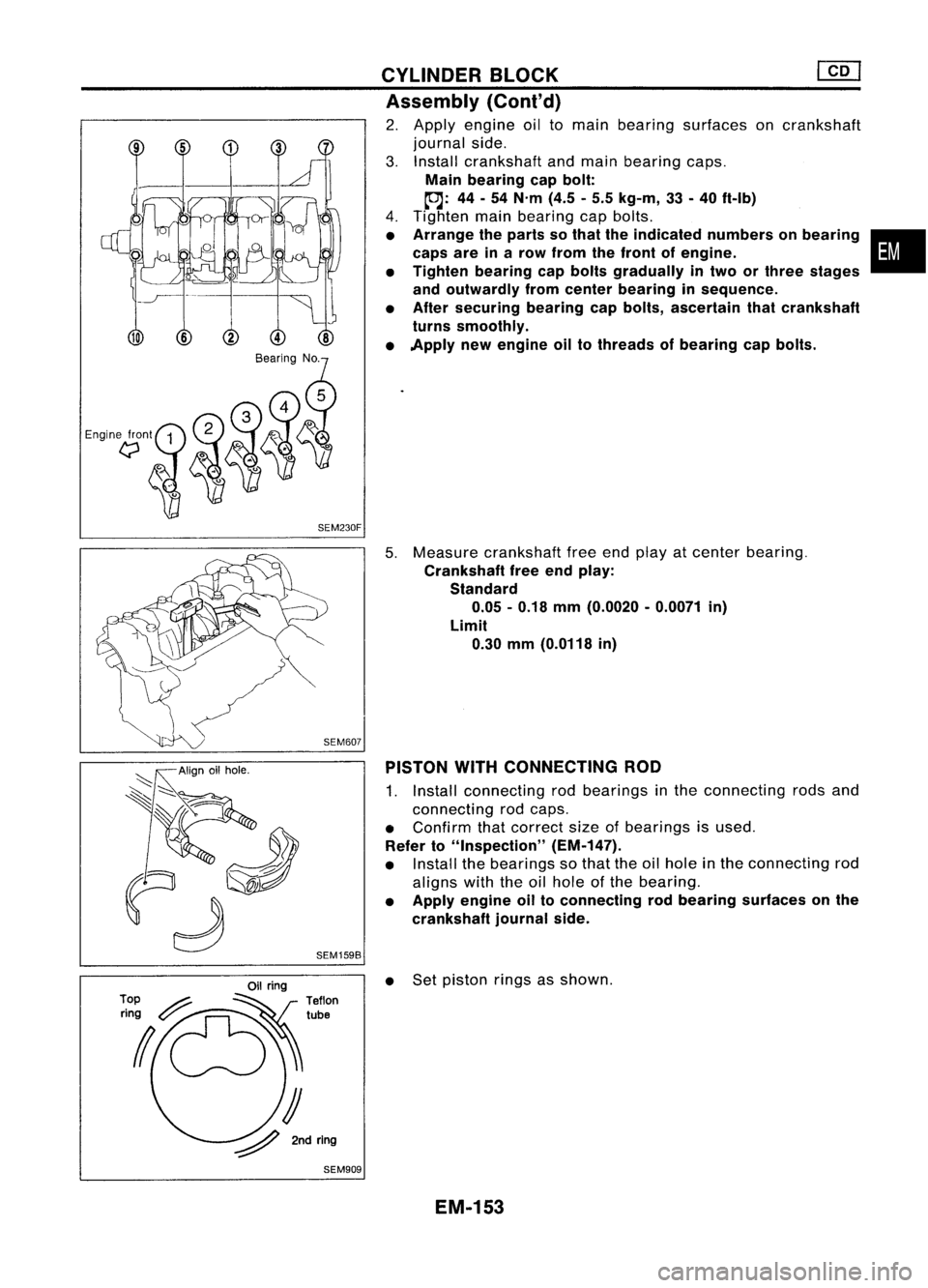
2. Apply engine oiltomain bearing surfaces oncrankshaft
journal side.
3. Install crankshaft andmain bearing caps.
Main bearing capbolt:
~: 44-54 N'm (4.5-5.5 kg-m, 33-40 ft-Ib)
4. Tighten mainbearing capbolts.
• Arrange theparts sothat theindicated numbersonbearing •
caps areinarow from thefront ofengine.
• Tighten bearing capbolts gradually intwo orthree stages
and outwardly fromcenter bearing insequence.
• After securing bearingcapbolts, ascertain thatcrankshaft
turns smoothly.
• Apply newengine oiltothreads ofbearing capbolts.
5. Measure crankshaft freeendplay atcenter bearing.
Crankshaft freeendplay:
Standard 0.05 -0.18 mm(0.0020 -0.0071 in)
Limit 0.30 mm(0.0118 in)
PISTON WITHCONNECTING ROD
1. Install connecting rodbearings inthe connecting rodsand
connecting rodcaps.
• Confirm thatcorrect sizeofbearings isused.
Refer to"Inspection" (EM-147).
• Install thebearings sothat theoilhole inthe connecting rod
aligns withtheoilhole ofthe bearing.
• Apply engine oiltoconnecting rodbearing surfaces onthe
crankshaft journalside.
• Set piston ringsasshown.
EM-153
Page 1333 of 1701
EM03470000orsuitable tool CYLINDER
BLOCK
lliJ
Assembly
(Conl'd)
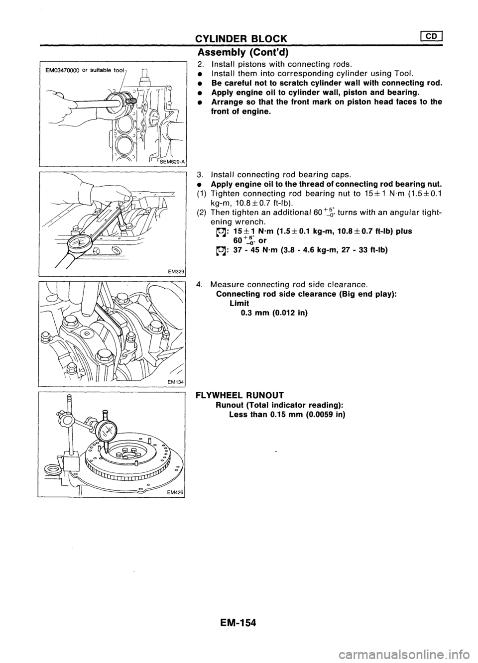
2. Install pistons withconnecting rods.
• Install themintocorresponding cylinderusingTool.
• Becareful nottoscratch cylinder wallwithconnecting rod.
• Apply engine oiltocylinder wall,piston andbearing.
• Arrange sothat thefront mark onpiston headfaces tothe
front ofengine.
3. Install connecting rodbearing caps.
• Apply engine oiltothe thread ofconnecting rodbearing nut.
(1) Tighten connecting rodbearing nutto15:1:1 N'm(1.5:1:0.1
kg-m, 10.8:1:0.7ft-Ib).
(2) Then tighten anadditional 60
+_~'.
turns withanangular tight-
ening wrench.
~: 15:1:1 N'm(1.5:1:0.1 kg-m,10.8:1:0.7 ft-Ib)plus
60+'::;.
or
~: 37-45 N'm (3.8-4.6 kg-m, 27-33 ft-Ib)
4. Measure connecting rodside clearance.
Connecting rodside clearance (Bigendplay):
Limit
0.3
mm (0.012 in)
FLYWHEEL RUNOUT
Runout (Totalindicator reading):
Less than0.15mm(0.0059 in)
EM-154
Page 1334 of 1701
SERVICEDATAANDSPECIFICATIONS (SOS)
General Specifications
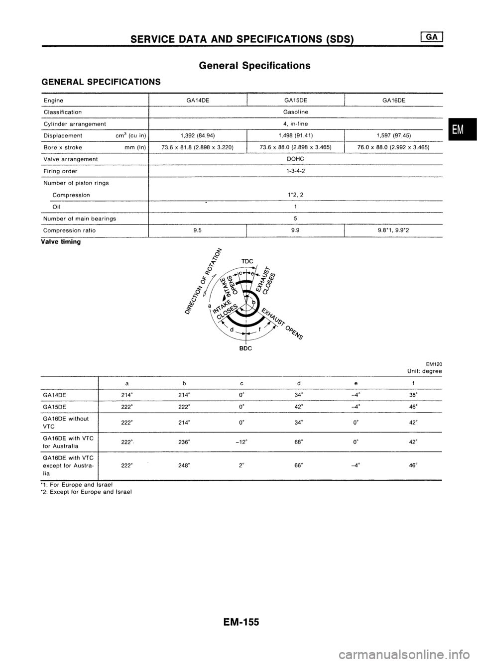
GENERAL SPECIFICATIONS
Engine GA14DE
GA15DE
GA16DE
Classification Gasoline
Cylinder arrangement 4,
in-line
Displacement cm
3
(cuin) 1,392(84.94) 1,498
(91.41)
1.597(97.45)
Bore xstroke mm(in) 73.6x81.8 (2.898 x3.220) 73.6
x88.0 (2.898 x3.465) 76.0x88.0 (2.992 x3.465)
Valve arrangement DOHC
Firing order 1-3-4-2
Number ofpiston rings
Compression 1'2,2
.
Oil 1
Number ofmain bearings 5
Compression ratio 959.9
9.8'1,9.9'2
Valve timing
~-r-y'
~U&l'
f
0,0
~J}&
BOC
EM120
Unit: degree
a b
cde
GA14DE 214"214° 0°
34° _4°
38°
GA15DE 222°
222° 0"
42°
-40
46°
GA16DE without
222° 214° 0°
34° 0°
VTC 42°
GA16DE withVTC
222" 236°_12°
68°0°42"
for Australia
GA16DE withVTC
except forAustra- 222°
248° 2"
66°
-4"
46"
lia
'1: For Europe andIsrael
'2: Except forEurope andIsrael
EM-155
•
Page 1335 of 1701
SERVICEDATAANDSPECIFICATIONS (50S)
Inspection andAdjustment
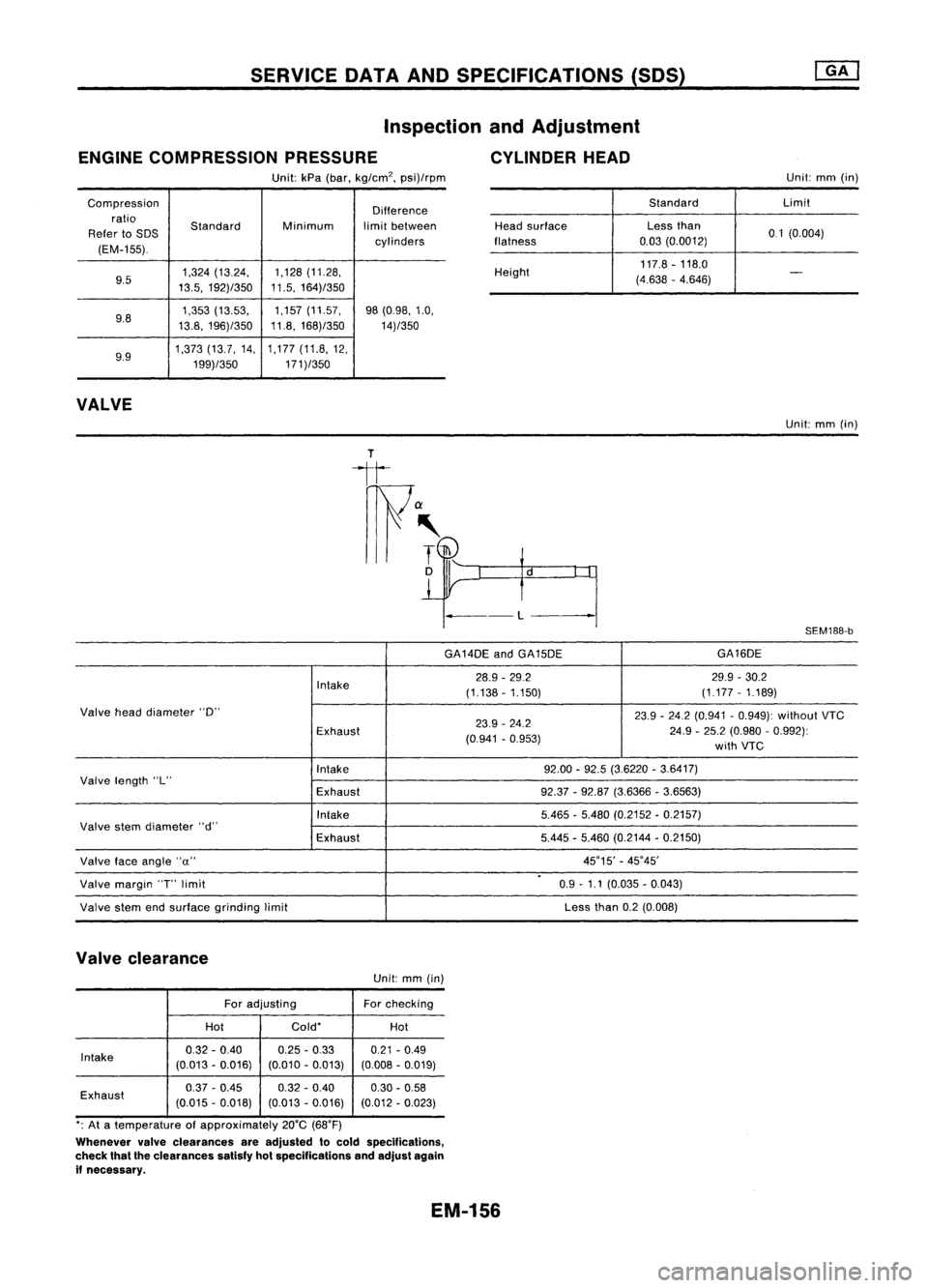
ENGINE COMPRESSION PRESSURE CYLINDERHEAD
Unit: kPa(bar, kg/cm
2,
psi)/rpm Unit:
mm(in)
Compression Difference
ratio Standard Minimumlimitbetween
Refer toSDS
cylinders
(EM-155).
9.5 1,324
(13.24, 1,128
(11.28,
13.5, 192)/350 11.5,
164)/350
9.8 1,353
(13.53, 1,157
(11.57,
98(0.98, 1.0,
13.8, 196)/350 11.8,
168)/350
14)/350
9.9 1,373
(13.7,14, 1,177
(11.8,12,
199)/350 171)/350
VALVE
Standard
Limit
Head surface Lessthan
0.1(0.004)
flatness 0.03
(0.0012)
Height 117.8
-118.0
(4.638 -4.646)
-
Unit: mm(in)
---L
SEM188-b
GA14DE andGA15DE GA16DE
Intake 28.9
-29.2 29.9-30.2
(1.138 -1.150) (1.177
-1.189)
Valve headdiameter "0"
23.9-24.2 (0.941 -0.949): without VTC
Exhaust 23.9
-24.2
24.9-25.2 (0.980 -0.992):
(0.941 -0.953)
withVTC
Intake 92.00
-92.5 (3.6220 -3.6417)
Valve length "L"
Exhaust 92.37-92.87 (3.6366 -3.6563)
Intake 5.465-5.480 (0.2152 -0.2157)
Valve stemdiameter "d"
Exhaust 5.445
-5.460 (0.2144 -0.2150)
Valve faceangle "u" 45°15'
-45°45'
.
Valve margin
'T'
limit 0.9-1.1 (0.035 -0.043)
Valve stemendsurface grinding limit Less
than0.2(0.008)
Valve clearance
Unit:mm(in)
For adjusting Forchecking
Hot Cold*
Hot
Intake 0.32
-0.40 0.25
-0.33
0.21-0.49
(0.013 -0.016) (0.010-0.013) (0.008-0.019)
Exhaust 0.37
-0.45 0.32-0.40
0.30-0.58
(0.015 -0.018) (0.013-0.016) (0.012-0.023)
*: At atemperature ofapproximately 20°C(68°F)
Whenever valveclearances areadjusted tocold specifications,
check thattheclearances satisfyhotspecifications andadjust again
if necessary.
EM-156
Page 1336 of 1701
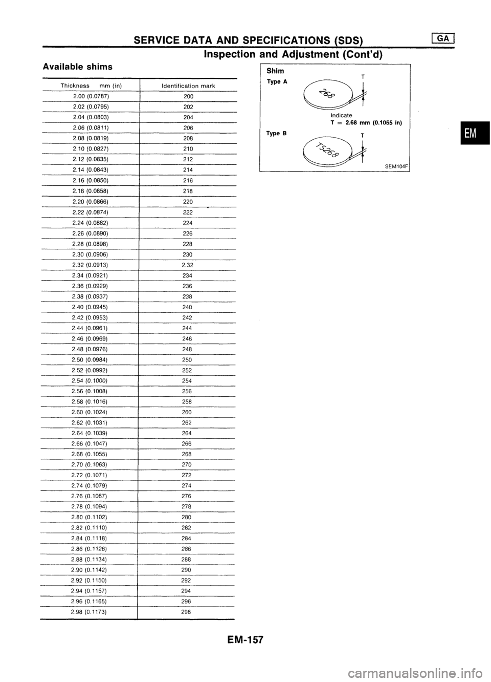
SERVICEOATAAND SPECIFICATIONS (SOS)
Inspection andAdjustment (Cont'd)
Indicate
T
=
2.68
mm
(0.1055 In)
Available
shims
Thickness mm(in)
Identificationmark
2.00 (0.0787)
200
2.02 (0.0795)
202
2.04 (0.0803)
204
2.06 (0.0811)
206
2.08 (0.0819)
208
210 (0.0827)
210
2.12 (00835)
212
2.14 (0.0843)
214
216 (0.0850)
216
2.18 (0.0858) 218
2.20 (0.0866) 220
2.22 (00874) 222
224 (00882)
224
2.26 (0.0890)
226
2.28 (0.0898) 228
2.30 (0.0906)
230
2.32 (0.0913) 2.32
2.34 (0.0921)
234
2.36 (0.0929)
236
2.38 (0.0937)
238
240 (0.0945)
240
2.42 (0.0953) 242
2.44 (0.0961) 244
2.46 (0.0969)
246
2.48 (0.0976) 248
2.50 (00984)
250
2.52 (0.0992) 252
2.54 (0.1000)
254
2.56 (01008) 256
2.58 (0.1016) 258
2.60 (0.1024)
260
262 (0.1031) 262
2.64 (0.1039) 264
2.66 (0.1047)
266
2.68 (0.1055) 268
2.70 (0.1063) 270
2.72 (0.1071) 272
2.74 (0.1079) 274
2.76 (0.1087) 276
278 (0.1094)
278
2.80 (01102) 280
282 (01110) 282
284 (0.1118)
284
286 (0.1126) 286
2.88 (01134)
288
290 (0.1142) 290
2.92 (0.1150) 292
294 (0.1157)
294
296 (0.1165) 296
2.98 (0.1173) 298Shim
Type A
Type B
SEM104F
•
EM-157
Page 1337 of 1701
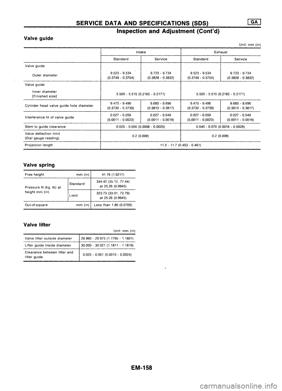
Valveguide SERVICE
DATAANDSPECIFICATIONS (50S)
Inspection andAdjustment (Cont'd)
Unit:mm(in)
Intake Exhaust
Standard ServiceStandard
Service
Valve gUide
Outer diameter 9.523
-9.534 9.723-9.734 9523-9.534
9.723-9.734
(0.3749 -0.3754) (0.3828-03832)
(0.3749-0.3754) (0.3828-0.3832)
Valve guide
Inner diameter
5500-5.515 (0.2165 -0.2171) 5.500-5.515 (0.2165 -0.2171)
[Finished size]
Cylinder headvalve guide holediameter 9.475
-9.496
9.685-9.696 9.475-9.496 9.685-9.696
(0.3730 -0.3739) (0.3813-0.3817)
(0.3730-0.3739) (0.3813-0.3817)
Interference fit
01
valve guide 0.027
-0.059 0.027-0.049 0.027-0.059 0.027-0.049
(0.0011 -0.0023)
(0.0011-0.0019) (0.0011
-0.0023) (0.0011-0.0019)
Stem toguide clearance
0.020-0.050 (0.0008 -0.0020) 0.040-0.070 (0.0016 -0.0028)
Valve deflection limit
0.2(0.008) 0.2(0.008)
(Dial gauge reading)
Projection length
11.5-11.7 (0.453 -0.461)
Valve spring
Free height
mm(in) 41.19
(1.6217)
Standard 344.42
(35.12, 77.44)
Pressure N(kg, Ib)at at
25.26 (0.9945)
height mm(in)
32373(33.01. 72.79)
Limit
at25.26 (0.9945)
Out-aI-square mm(in) Lessthan1.80(0.0709)
Valve lifter
Unit:mm(in)
Valve lifteroutside diameter
Lifter guide inside diameter
Clearance betweenlifterand
lifter guide 29.960
-29.975 (1.1795 -1.1801)
30000 -30.021 (1.1811 -1.1819)
0.025 -0.061 (0.0010 -0.0024)
EM-158
Page 1338 of 1701
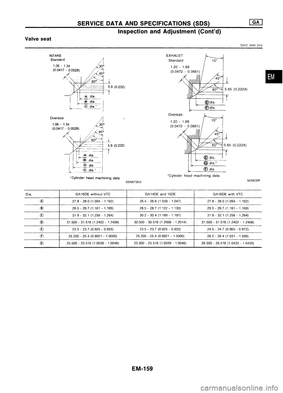
SERVICEDATAANDSPECIFICATIONS (50S)
Inspection andAdjustment (Cont'd)
Valve seat
Unit:mm(in)
•
SEM239F
5.65
(0.2224)
5.65 (0.2224)
Oversize.
@dia.
~dia~.-'--
'Cylinder headmachining data
EXHAUST
Standard
SEM573DA
•
Cylinder headmachining data
INTAKE
Standard
Dia. GA16DE
withoutVTe GA14DE
and15DE
GA16DEwithVTe
@ 27.8-28.0 (1094 -1 102) 26.4-26.6 (1.039 -1.047) 27.8-28.0 (1.094 -1.102)
@ 29.5-29.7 (1.161 -1.169) 285
-28.7 (1.122 -1.130)
29.5-29.7 (1.161 -1.169)
@ 319-32.1 (1.256 -1.264) 302-30.4 (1.189 -1.197) 31.9-32.1 (1.256 -1.264)
@ 31.500-31.516 (1.2402 -1.2408) 30.500
-30.516 (1.2008 -1.2014) 31.500-31.516 (1.2402 -1.2408)
(f)
23.5-23.7 (0.925 -0.933) 235
-23.7 (0.925 -0.933) 24.5-247 (0.965 -0.972)
CD
25.200
-25.4 (0.9921 -1.0000) 25.200-25.4 (0.9921 -1.0000) 26.2-26.4 (1.031 -1.039)
@ 25.500-25516 (1.0039 -1.0046) 25.500-25.516 (1.0039 -1.0046) 26.500-26.516 (1.0433 -1.0439)
EM-159
Page 1339 of 1701
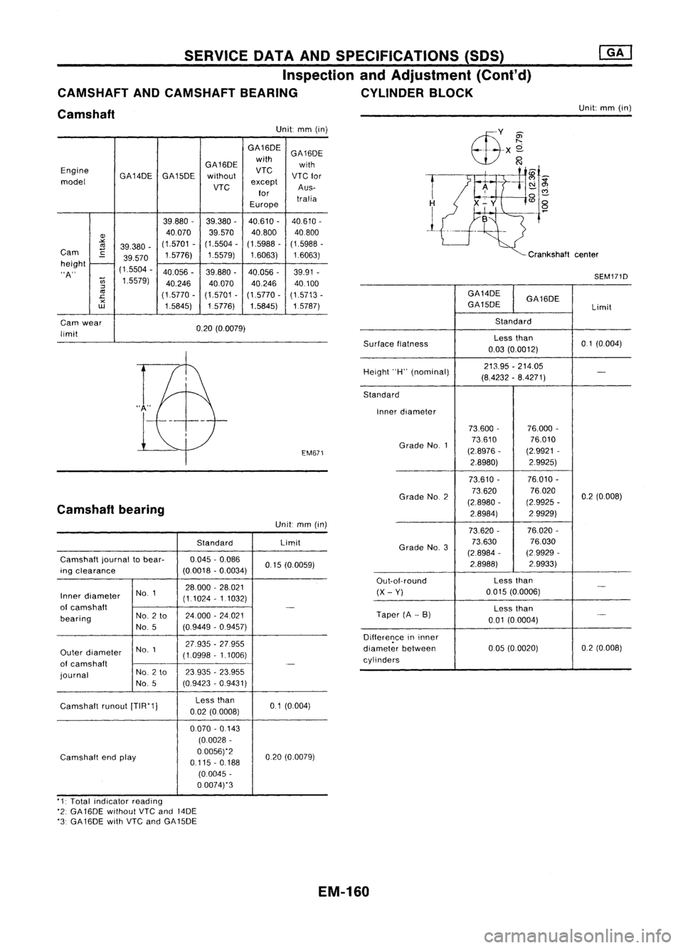
SERVICEOATAAND SPECIFICATIONS (SOS)
Inspection andAdjustment (Cont'd)
CAMSHAFT ANDCAMSHAFT BEARING CYLINDERBLOCK
Camshaft
Unit:
mm(in)
Unit: mm(in)
GA16DE GA16DE
GA16DE with
with
Engine GA14DEGA15DE without
VTC
VTC
for
model
VTC
except
Aus-
for tralia
Europe
39,880 -
39,380 -40,610
-
40,610 -
Q)
40070
39,570
40,800
40800
""
(1.5701
-(1.5504 -(1.5988 -(1.5988 -
<1l
39,380 -
Cam
C
1.5776)1.5579)1.6063) 1.6063)
39.570
height
-
"A" (1,5504
-
40.056 -39.880 -
40.056 -39.91
-
U;
1.5579)
40.24640,07040.246 40.100
:::l
<1l
(1.5770-(1.5701-(1.5770 -(1.5713 -
.c
x
1,5845)1,5776)
1.5845) 1,5787)
w
Cam wear
0.20(0.0079)
limit
EM671
Camshaft bearing
Unit:mm(in)
Standard Limit
Camshaft journaltobear- 0,045
-0.086
0,15(0.0059)
ing clearance (00018-0.0034)
NO.1 28.000
-28,021
Inner diameter
(1.1024-1 1032)
of camshaft
-
bearing No.
2to 24,000
-24021
No, 5 (0.9449
-0.9457)
NO.1 27.935
-27.955
Outer diameter
(1,0998-1.1006)
of camshaft
.-
journal No.
2to 23935
-23.955
No, 5 (0,9423
-0,9431)
Camshaft runout[TIR'1] Less
than
01(0,004)
0.02 (0.0008)
0070 -0 143
(0,0028 -
Camshaft endplay 0.0056)'2
020(0,0079)
0,115 -0,188
(0.0045 -
0.0074)'3
T
1
Crankshaftcenter
SEM171D
GA14DE GA16DE
GA15DE Limit
Standard
Surface flatness Less
than
0,1(0,004)
0,03 (0.0012)
Height "H"(nominal) 213.95
-214.05
-
(8.4232 -8.4271)
Standard Inner diameter
73.600- 76.000-
Grade No.1 73,610
76,010
(2.8976 -(2,9921
-
2.8980) 2.9925)
73.610 - 76.010
-
Grade NO.2 73,620
76020
0.2(0,008)
(2.8980 -(2.9925
-
2.8984) 2.9929)
73,620 - 76.020-
Grade No.3 73.630
76.030
(2,8984 -(2.9929 -
2.8988) 2,9933)
Out-ot-round Less
than
-
(X -Yi
0,015
(0.0006)
Less than
Taper (A-B)
._-
0.01 (0.0004)
Difference ininner
diameter between 005
(0,0020) 0,2
(0.008)
cylinders
'1: Total indicator reading
'2: GA 16DE without
VTC
and 14DE
'3: GA16DE withVTC andGA15DE
EM-160
Page 1340 of 1701
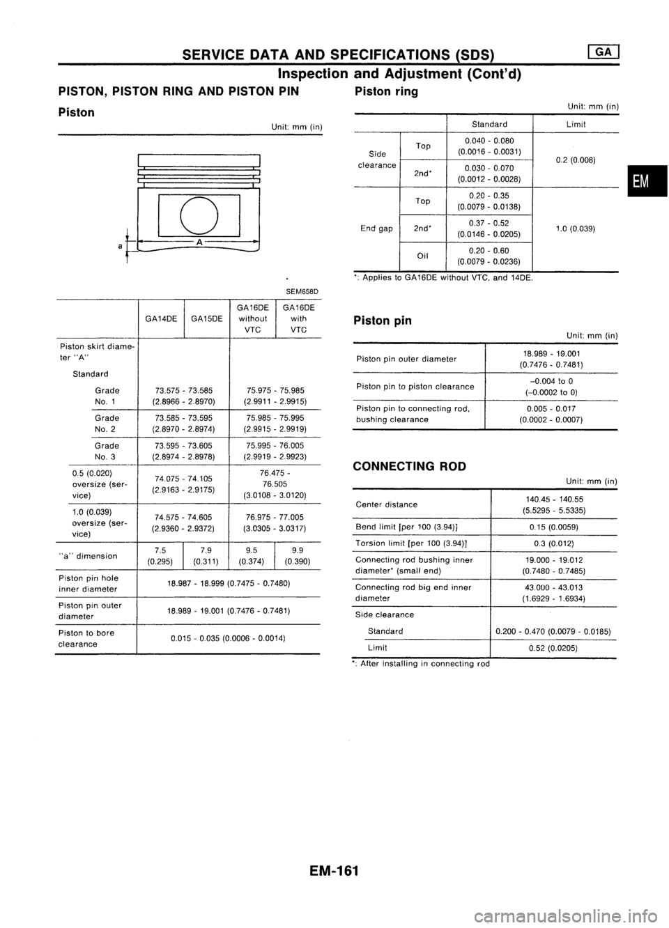
•
Unit:
mm(in)
Standard Limit
Top 0.040
-0.080
Side (0.0016
-0.0031)
clearance 0.2
(0.008)
2nd' 0.030
-0.070
(0.0012 -0.0028)
Top 0.20
-0.35
(0.0079 -0.0138)
End gap 2nd' 0.37
-0.52
1.0(0.039)
(0.0146 -0.0205)
Oil 0.20
-0.60
(0.0079 -0.0236)
Unit:
mm(in)
SERVICE
OATAAND SPECIFICATIONS (SDS)
Inspection andAdjustment (Cont'd)
PISTON, PISTONRINGANDPISTON PIN Pistonring
Piston
':Applies toGA16DE withoutVTC,and14DE.
SEM658D
Centerdistance 140.45
-140.55
(5.5295 -5.5335)
Bend limit[per100(3.94)]
0.15(0.0059)
Torsion limit[per100(3.94)]
0.3(0.012)
Connecting rodbushing inner
19.000-19.012
diameter' (smallend)
(0.7480-0.7485)
Connecting rodbigend inner
43.000-43.013
diameter (1.6929-1.6934)
Side clearance
Standard 0.200-0.470 (0.0079 -0.0185)
Limit 0.52(0.0205)
Piston
pin
GA16DE
GA16DE
GA14DE GA15DE without with
VTC VTC
Piston skirtdiame-
ter "A"
Standard
Grade 73.575-73.585 75.975-75.985
NO.1 (2.8966-2.8970) (29911
-2.9915)
Grade 73.585-73.595 75.985
-75.995
No. 2 (2.8970
-2.8974) (2.9915-2.9919)
Grade 73.595-73.605 75.995-76.005
No. 3 (2.8974-2.8978) (2.9919
-2.9923)
05 (0.020)
74.075-74105 76.475
-
oversize (ser-
(2.9163-2.9175) 76.505
vice) (3.0108
-3.0120)
1.0 (0.039)
74.575-74.605 76.975-77.005
oversize (ser-
(2.9360-2.9372) (3.0305
-3.0317)
vice)
"a" dimension 7.5
7.99.5 9.9
(0.295) (0.311)
(0.374) (0.390)
Piston pinhole
18.987-18.999 (0.7475 -0.7480)
inner diameter
Piston pinouter
18.989-19.001 (0.7476 -0.7481)
diameter
Piston tobore
0.015-0035 (0.0006 -0.0014)
clearance Piston
pinouter diameter
Piston pintopiston clearance
Piston pintoconnecting rod,
bushing clearance
CONNECTING ROD Unit:
mm(in)
18.989 -19.001
(0.7476 -0.7481)
-0.004 to0
(-0.0002 to0)
0.005 -0.017
(0.0002 -0.0007)
Unit: mm(in)
': After installing inconnecting rod
EM-161