NISSAN ALMERA N15 1995 Service Manual
Manufacturer: NISSAN, Model Year: 1995, Model line: ALMERA N15, Model: NISSAN ALMERA N15 1995Pages: 1701, PDF Size: 82.27 MB
Page 1341 of 1701
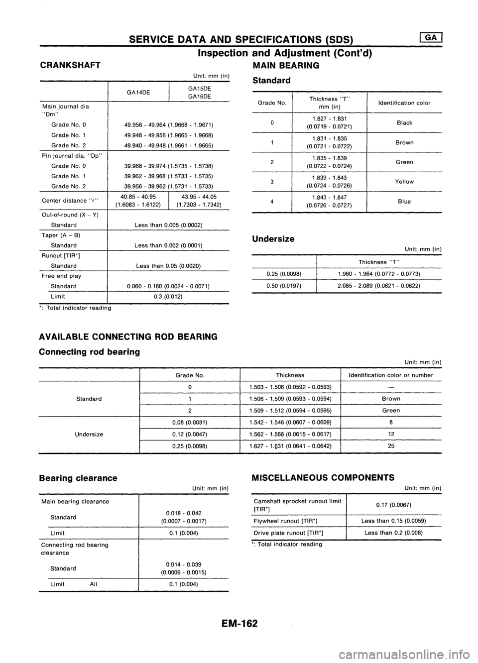
CRANKSHAFT SERVICE
DATAANDSPECIFICATIONS (SOS)
Inspection andAdjustment (Cont'd)
MAIN BEARING
Grade No. Thickness
"T"
Identificationcolor
mm (in)
0 1.827
-1.831
Black
(0.0719 -0.0721)
1 1.831
-1.835
Brown
(0.0721 -0.0722)
2 1.835
-1.839
Green
(0.0722 -0.0724)
3 1.839
-1.843
Yellow
(0.0724 -0.0726)
4 1.843
-1.847
Blue
(0.0726 -0.0727)
Unit:
mm(in)
GA14DE
I
GA15DE
GA16DE
Main journal dia.
"Dm"
Grade No.0 49.956-49.964 (1.9668 -1.9671)
Grade NO.1 49.948-49.956 (1.9665 -1.9668)
Grade NO.2
49.940-49.948 (1.9661 -1.9665)
Pin journal dia."Dp"
Grade No.0 39.968-39.974 (1.5735 -1.5738)
Grade NO.1
39.962-39.968 (1.5733 -1.5735)
Grade No.2 39.956-39.962 (1.5731 -1.5733)
Center distance "r" 40.85
-40.95
I
43.95
-44.05
(1.6083 -1.6122) (1.7303-1.7342)
Out-ot-round (X-Y)
Standard Lessthan0.005 (0.0002)
Taper (A-B)
Standard Lessthan0.002 (0.0001)
Runout [TIW]
Standard Lessthan0.05(0.0020)
Free endplay
Standard 0.060-0.180 (0.0024 -0.0071)
Limit 0.3(0.012)
': Total indicator reading Standard
Undersize 0.25(0.0098)
0.50 (0.0197) Unit:
mm(in)
Thickness "T"
1.960 -1.964 (0.0772 -0.0773)
2.085 -2.089 (0.0821 -0.0822)
AVAILABLE CONNECTING RODBEARING
Connecting rodbearing
Unit:mm(in)
Grade No. Thickness
Identificationcolorornumber
0 1.503
-1.506 (0.0592 -0.0593)
-
Standard 11.506-1.509 (0.0593 -0.0594) Brown
2 1.509
-1.512 (0.0594 -0.0595) Green
0.08 (0.0031) 1.542
-1.546 (0.0607 -0.0609)
8
Undersize 0.12(0.0047) 1.562
-1.566 (0.0615 -0.0617) 12
0.25 (0.0098) 1.627
-1.931 (0.0641 -0.0642) 25
Bearing clearance
Unit:mm(in) MISCELLANEOUS
COMPONENTS
Unit:mm(in)
Main bearing clearance
Standard Limit
Connecting rodbearing
clearance 0.018
-0.042
(0.0007 -0.0017)
0.1 (0.004) Camshaft
sprocketrunoutlimit
[TIW]
Flywheel runout[TIW]
Drive platerunout [T1R']
': Total indicator reading 0.17
(0.0067)
Less than0.15(0.0059)
Less than0.2(0.008)
Standard Limit All 0.014
-0.039
(0.0006 -0.0015)
0.1 (0.004)
EM-162
Page 1342 of 1701
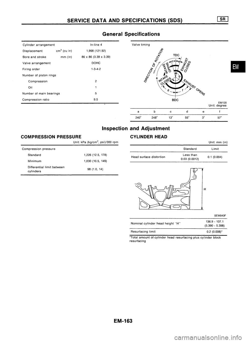
SERVICEDATAANDSPECIFICATIONS (50S)
General Specifications
Number ofmain bearings
Cylinder
arrangement
Displacement
Bore andstroke
Valve arrangement
Firing order
Number ofpiston rings
Compression
Oil
Compression ratiocm
3
(cuin)
mm (in) In-line
4
1,998 (121.92)
86 x86 (3.39 x3.39)
DOHC
1-3-4-2
2
5
9.5 Valve
timing
BOC EM120
Unit: degree
•
COMPRESSION PRESSURE a
Inspection andAdjustment
CYLINDER HEADc
e
Unit: kPa(kg/cm
2,
psi)/300rpm
Compression pressure StandardUnit:
mm(in)
Limit
Standard
Minimum 1,226
(12.5, 178)
1,030 (10.5, 149) Head
surface distortion Less
than
0.03 (0.0012) 0.1
(0.004)
Differential limitbetween
cylinders 98
(1.0, 14)
H
SEM043F
Nominal cylinder headheight "H"
Resurfacing limit 136.9
-137.1
(5.390 -5.398)
0.2 (0.008)"
'Total amount ofcylinder headresurfacing pluscylinder block
resurfacing
EM-163
Page 1343 of 1701
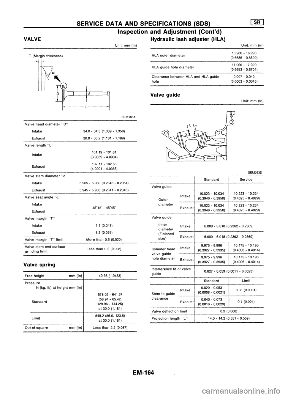
VALVE SERVICE
DATAANDSPECIFICATIONS (SOS)
Inspection andAdjustment (Cont'd)
Hydraulic lashadjuster (HLA)
Unit: mm(in) Unit:
mm(in)
T (Margin thickness)
1
r-
r1)1a
III' ~
o
L
HLA
outer diameter
HLA guide holediameter
Clearance betweenHLAandHLA guide
hole
Valve guide 16.980
-16.993
(0.6685 -0.6690)
17.000 -17.020
(0.6693 -0.6701)
0.007 -0.040
(0.0003 -0.0016)
Unit: mm(in)
Pressure N(kg, Ib)atheight mm(in)5965
-5.980 (0.2348 -0.2354)
5.945 -5.960 (0.2341 -0.2346) SEM083D
Standard Service
Valve gUide
Intake 10.023
-10.034 10.223
-10.234
Outer (0.3946
-0.3950) (0.4025-0.4029)
diameter 10.023-10.034 10.223
-10.234
Exhaust (0.3946-0.3950) (0.4025
-0.4029)
Valve gUide
Inner Intake 6.000-6018 (0.2362 -0.2369)
diameter
(Finished Exhaust 6.000
-6.018 (0.2362 -0.2369)
size)
Intake9.975
-9.996 10.175-10.196
Cylinder head
(0.3927-0.3935) (0.4006
-0.4014)
valve guide
hole diameter
Exhaust 9.975
-9.996 10.175-10.196
(0.3927 -0.3935) (0.4006
-0.4014)
Interference fitofvalve
0.027-0.059 (0.0011 -0.0023)
guide
StandardLimit
Intake 0.020
-0.053
0.08(0.0031)
Stem toguide (0.0008
-0.0021)
clearance 0.040-0.073
Exhaust (0.0016-0.0029) 0.1
(0.004)
Valve deflection limit 0.2
(0.008)
Projection length"L" 14.0
-14.2 (0.551 -0.559)
49.36
(1.9433)
578.02 -641.57
(58.94 -65.42,
129.96 -144.25)
at 30.0 (1.181)
549.2 (56.0, 123.5)
at 30.0 (1.181)
Less than2.2(0.087)SEM188A
101.19 -101.61
(3.9839 -4.0004)
102.11 -102.53
(4.0201 -4.0366)
Less than0.2(0.008)
1.1
(0.043)
1.3 (0.051)
More than0.5(0.020)
34.0
-34.3 (1.339 -1.350)
30.0 -30.2 (1.181 -1.189)
mm(in)
mm(in)
Limit
Standard Intake
Exhaust
Exhaust
Exhaust
Intake
Exhaust
Valve
length "L"
Intake
Valve stemdiameter "d"
Valve
headdiameter "0"
Intake
Exhaust
Valve margin "T"
Valve margin "T"limit
Valve stemendsurface
grinding limit
Valve
seatangle
"a"
Intake
Free height
Out-aI-square
Valve
spring
EM-164
Page 1344 of 1701
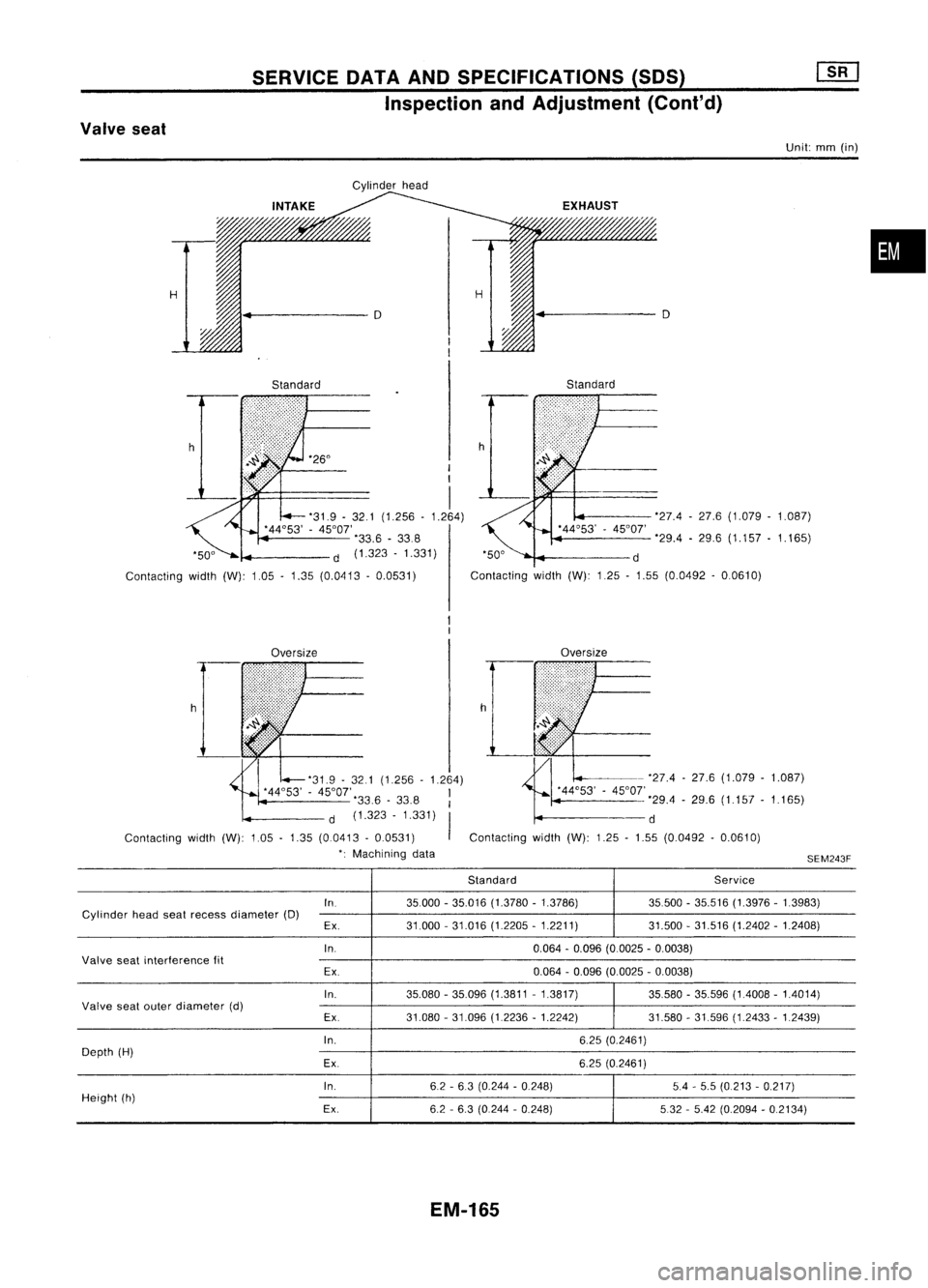
SERVICEDATAANDSPECIFICATIONS (SOS)
Inspection andAdjustment (Cont'd)
Valve seat
Unit:mm(in)
Cylinder head
•
H H
4
D D
Standard Standard
h '26°
I
I
I
'31.9 -32.1 (1.256 -1.264)
'44°53' -45°01'
'33.6-338
d (1.323 -1.331)
Contacting width(W):1.05-1.35 (0.0413 -0.0531) '27.4
-27.6 (1.079 -1.087)
'29.4 -29.6 (1.157 -1.165)
'50° d
Contacting width(W):125-1.55 (0.0492 -0.0610)
Oversize Oversize
'31.9 -321 (1.256 -1.264)
'44°53' -45°01', I
33.6 -33.8 I
d (1.323 -1.331)
I
Contacting width(W):1.05-1.35 (00413 -0.0531)
': Machining data h
-'27.4 -27.6 (1.079 -1.087)
'44°53' -45°01'
'29.4-29.6 (1.157 -1.165)
d
Contacting width(W):1.25-1.55 (0.0492 -0.0610)
SEM243F
Standard Service
In. 35000-35.016 (1.3780 -1.3786) 35500-35.516 (1.3976 -1.3983)
Cylinder headseatrecess diameter (D)
Ex. 31.000
-31.016 (1.2205 -1.2211) 31.500-31.516 (1.2402 -1.2408)
In. 0.064-0.096 (0.0025 -0.0038)
Valve seatinterference fit
Ex. 0.064
-0.096 (0.0025 -0.0038)
In. 35.080-35.096 (1.3811 -1.3817) 35.580-35.596 (1.4008 -1.4014)
Valve seatouter diameter (d)
Ex.31.080-31.096 (1.2236 -1.2242) 31.580-31.596 (1.2433 -1.2439)
In. 6.25(0.2461)
Depth (H)
Ex. 6.25(0.2461)
In. 62-63 (0.244 -0.248) 5.4-5.5 (0.213 -0.217)
Height (h)
Ex.6.2-6.3 (0.244 -0.248) 532-5.42 (0.2094 -0.2134)
EM-165
Page 1345 of 1701
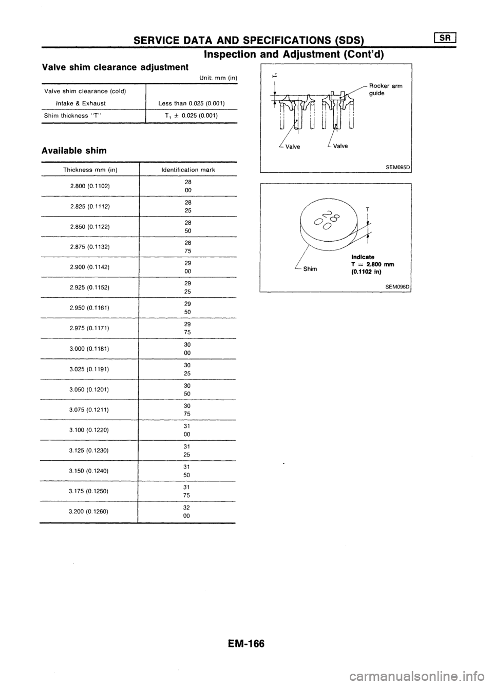
SERVICEDATAANDSPECIFICATIONS (SDS)
Inspection andAdjustment (Cont'd)
Valve shimclearance adjustment
Valve shimclearance (cold)
Intake &Exhaust
Shim thickness "T"
Available shim Unit:
mm(in)
Less than0.025 (0.001)
T, :l:0.025 (0.001) Rocker
arm
guide
Thickness mm(in) Identification
mark
2.800 (0.1102) 28
00
2.825 (0.1112) 28
25
2.850 (0.1122) 28
50
2.875 (0.1132) 28
75
2.900 (0.1142) 29
00
2.925 (0.1152) 29
25
2.950 (0.1161) 29
50
2.975 (0.1171) 29
75
3.000 (0.1181) 30
00
3.025 (0.1191) 30
25
3.050 (0.1201) 30
50
3.075 (0.1211) 30
75
3.100 (0.1220) 31
00
3.125 (0.1230) 31
25
3.150 (01240) 31
50
3.175 (0.1250) 31
75
3.200 (0.1260) 32
00
EM-166 SEM095D
T
Indicate
T
=
2.800
mm
(0.1102 In)
SEM096D
Page 1346 of 1701
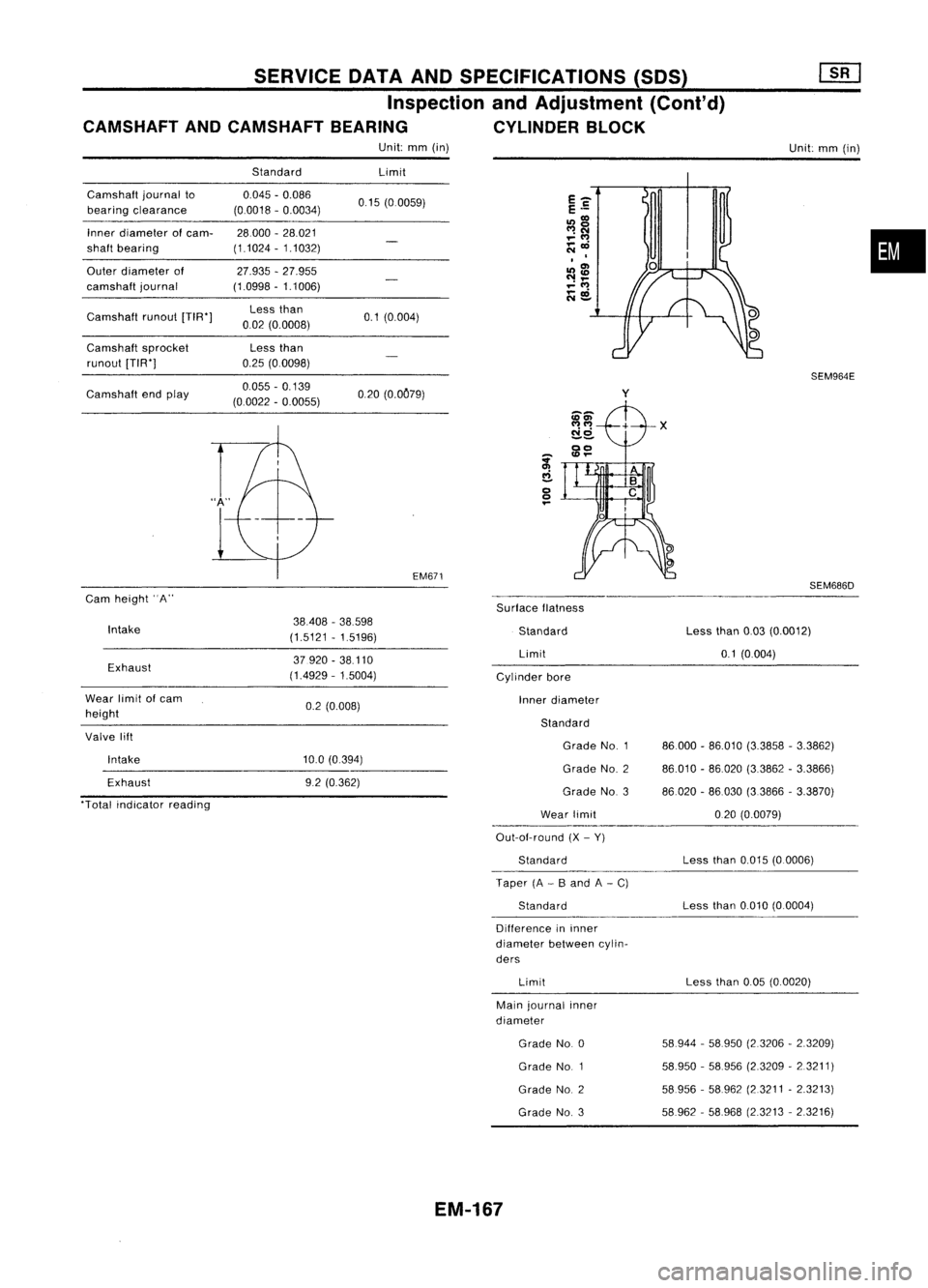
SERVICEDATAANDSPECIFICATIONS (SOS)
Inspection andAdjustment (Cont'd)
CAMSHAFT ANDCAMSHAFT BEARING CYLINDERBLOCK
Unit: mm(in)
Unit:mm(in)
Camshaft journalto
bearing clearance
Inner diameter
01
cam-
shaft bearing
Outer diameter of
camshaft journal
Camshaft runout[TIW]
Camshaft sprocket
runout [TIW]
Camshaft endplay
Cam height
"A"
Standard
0.045 -0.086
(0.0018 -0.0034)
28000 -28.021
(1.1024 -1.1032)
27.935 -27.955
(1.0998 -1.1006)
Less than
002 (0.0008)
Less than
0.25 (00098)
0.055 -0.139
(0.0022 -0.0055) Limit
0.15 (00059)
0.1 (0.004)
020 (0.OC79)
EM6?1
SurfaceIlatness
y
SEM964E
SEM686D
•
Intake
Exhaust
Wear limit
01
cam
height
Valve lift
Intake
Exhaust
"Total indicator reading 38408
-38.598
(1.5121 -1.5196)
37.920 -38.110
(14929 -1.5004)
0.2 (0.008)
10.0 (0.394)
9.2 (0.362) Standard
Limit
Cylinder bore
Inner diameter
Standard Grade No.1
Grade NO.2
Grade No.3
Wear limit
Out-aI-round (X-Y)
Standard
Taper (A-B and A-C)
Standard
Difference ininner
diameter betweencylin-
ders
Limit
Main journal inner
diameter
Grade No.0
Grade NO.1
Grade NO.2
Grade NO.3
EM-167
Less
than0.03(0.0012)
0.1 (0004)
86.000 -86.010 (3.3858 -3.3862)
86.010 -86020 (3.3862 -3.3866)
86020 -86.030 (33866 -3.3870)
020 (0.0079)
Less than0.015 (0.0006)
Less than0.010 (0.0004)
Less than0.05(0.0020)
58944 -58950 (2.3206 -2.3209)
58.950 -58.956 (2.3209 -2.3211)
58956 -58962 (2.3211 -2.3213)
58962 -58968 (23213 -2.3216)
Page 1347 of 1701
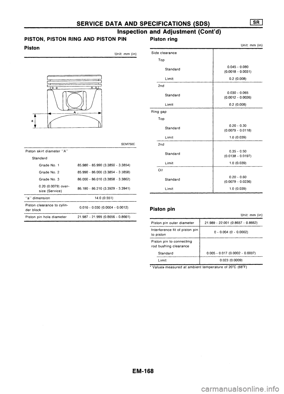
SERVICEDATAANDSPECIFICATIONS (SOS)
Inspection andAdjustment (Cont'd)
PISTON, PISTONRINGANDPISTON PIN Pistonring
Piston
Unit:
mm(in)
SEM750C
Piston skirtdiameter "A" Unit:
mm(in)
0.045-0.080
(0.0018 -0.0031)
0.2 (0.008)
020 -0.60
(0.0079 -0.0236)
1.0 (0.039)
0.030
-0.065
(0.0012 -0.0026)
0.2 (0.008)
0.20 -0.30
(0.0079 -0.0118)
1.0 (0.039)
0.35 -0.50
(0.0138 -0.0197)
1.0 (0.039)
Limit
Side
clearance
Top
Standard
Limit
2nd
Standard
Limit
Ring gap
Top
Standard
Limit
2nd
Standard
Limit
Oil
Standard
86.180 -86210 (3.3929 -3.3941)
85.980
-85.990 (3.3850 -3.3854)
85.990 -86.000 (3.3854 -3 3858)
86000 -86.010 (3.3858. 3.3862)
Grade NO.3
Grade
NO.1
Grade NO.2
020 (0.0079) over-
size (Service)
Standard
"a" dimension 14.0(0.551)
Piston clearance tocylin-
der block 0.010
-0.030 (0.0004 -0.0012)
Pistonpin
Piston pinhole diameter 21.987
-21.999 (0.8656 -0.8661) Unit:
mm(in)
Piston pinouter diameter
Interference fitofpiston pin
to piston 21.989
-22.001 (08657 -0,8662)
o -
0004 (0-0,0002)
Piston pintoconnecting
rod bushing clearance
Standard
Limit 0005
-0.017 (0,0002 -0,0007)
0,023 (0,0009)
• Values- measured atambient temperature of20°C (68°F)
EM-1G8
Page 1348 of 1701
![NISSAN ALMERA N15 1995 Service Manual SERVICEDATAANDSPECIFICATIONS (SDS)
Inspection andAdjustment (Cont'd)
CONNECTING ROD CRANKSHAFT
Unit:
mm
(in)
Unit:
mm
(in)
Center distance 136,30
(5,3661)
Bend [per100(3,94)]
Limit 0,15
(0,0059) NISSAN ALMERA N15 1995 Service Manual SERVICEDATAANDSPECIFICATIONS (SDS)
Inspection andAdjustment (Cont'd)
CONNECTING ROD CRANKSHAFT
Unit:
mm
(in)
Unit:
mm
(in)
Center distance 136,30
(5,3661)
Bend [per100(3,94)]
Limit 0,15
(0,0059)](/img/5/57349/w960_57349-1347.png)
SERVICEDATAANDSPECIFICATIONS (SDS)
Inspection andAdjustment (Cont'd)
CONNECTING ROD CRANKSHAFT
Unit:
mm
(in)
Unit:
mm
(in)
Center distance 136,30
(5,3661)
Bend [per100(3,94)]
Limit 0,15
(0,0059)
Torsion [per100(3,94)]
Limit 0,3
(0,012)
Connecting rodsmall end
24,980-25,000 (0,9835 -0,9843)
inner diameter
Piston pinbushing inner
22,000-22,012 (0,8661 -0,8666)
diameter'
Connecting rodbigend
51,000-51,013 (2,0079 -2,0084)
inner diameter
.
Side clearance
Standard 0,20
-0,35 (0,0079 -0,0138)
Limit 0,5
(0.020)
• After installing inconnecting rod Main
journal dia,"Om"
Grade No,0
Grade No,1
Grade No,2
Grade No,3
Pin journal dia,"Op"
Grade No,0
Grade No,
Grade No,2
Center distance "r"
Out-ot-round (X-Y)
Standard
Taper (A-B)
Standard
Runout
[TIR)
Standard
Limit
Free endplay
Standard
Limit 54.974
-54.980 (2,1643 -2,1646)
54.968 -54.974 (2.1641 -2,1643)
54.962 -54.968 (2,1639 -2,1641)
54,956 -54,962 (2,1636 -2,1639)
47968 -47,974 (1,8885 -1,8887)
47,962 -47.968 (1,8883 -1.8885)
47,956 -47,962 (1,8880 -1,8883)
42,96 -43,04 (1,6913 -1,6945)
Main journal Lessthan0,005 (0,0002)
Pin journal Lessthan0,0025 (0,0001)
Main journal Lessthan0,005 (0,0002)
Pin journal Lessthan0,0025 (0,0001)
Less than0.025 (0.0010)
Less than0.05(0,0020)
0,10 -0.26 (0,0039 -0,0102)
0.30 (0,0118)
Om
•
Op
Out-at-round
@-
(J)
Taper
@-@
LU
\JY
EM-169 @
@
SEM954C
Page 1349 of 1701
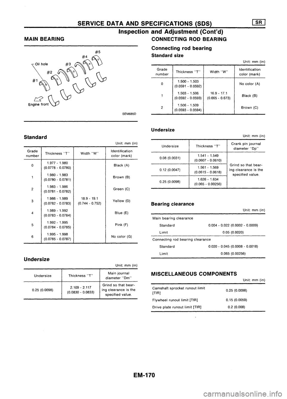
SEM685D
#5
#4 ~
~il hole #3~~ \)
#2 ~~'
#1~~~ ~~
L2 ~~
Engine front~
MAIN
BEARING SERVICE
DATAANDSPECIFICATIONS (SOS)
Inspection andAdjustment (Cont'd)
CONNECTING RODBEARING
Connecting rodbearing
Standard size
Unit:mm(in)
Grade Thickness"T"Width"W" Identification
number color(mark)
0 1.500
-1.503
Nocolor (A)
(0.0591 -0.0592)
1 1.503
-1.506 16.9-17.1
Black(B)
(0.0592 -0.0593) (0.665-0.673)
2 1.506
-1.509
Brown(C)
(0.0593 -0.0594)
Undersize
Standard
Unit:
mm(in)
Connecting rodbearing clearance
Undersize
Thickness
"T"
Crank
pinjournal
diameter "Op"
0.08 (0.0031) 1.541
-1.549
(0.0607 -0.0610)
1.561 -1.569
Grind
sothat bear-
0.12 (0.0047)
(0.0615-0.0618)
ing
clearance isthe
specified value.
0.25 (0.0098) 1.626
-1.634
(0.065 -0.00256)
Unit:
mm(in)
Grade Thickness "T"Width"W" Identification
number color
(mark)
0 1.977
-1.980
Black(A)
(0.0778 -0.0780)
1 1.980
-1.983
Brown(B)
(0.0780 -0.0781)
2 1.983
-1.986
Green(C)
(0.0781 -0.0782)
3 1.986-1.989
18.9-19.1
Yellow(D)
(0.0782 -0.0783) (0.744
-0.752)
4 1.989
-1.992
Blue(E)
(0.0783 -0.0784)
5 1.992
-1.995
Pink(F)
(0.0784 -0.0785)
6 1.995
-1.998
Nocolor (G)
(0.0785 -0.Q787)
Undersize
Unit:mm(in)
Bearing
clearance
Main bearing clearance
Standard
Limit
Standard
Limit Unit:
mm(in)
0.004 -0.022 (0.0002 -0.0009)
0.05 (0.0020)
0.020 -0.045 (0.0008 -0.0018)
0.065 (0.00256)
Undersize Thickness
"T" Main
journal
diameter "Om"
MISCELLANEOUS
COMPONENTS
Unit:mm(in)
0.25 (0.0098) 2.109
-2.117
(0.0830 -0.0833)
Grind
sothat bear-
ing clearance isthe
specified value. Camshaft
sprocketrunoutlimit
[TIR]
Flywheel runoutlimit[TIR]
Drive platerunout limit[TIA]
0.25
(0.0098)
0.15 (0.0059)
0.2 (0.008)
EM-170
Page 1350 of 1701
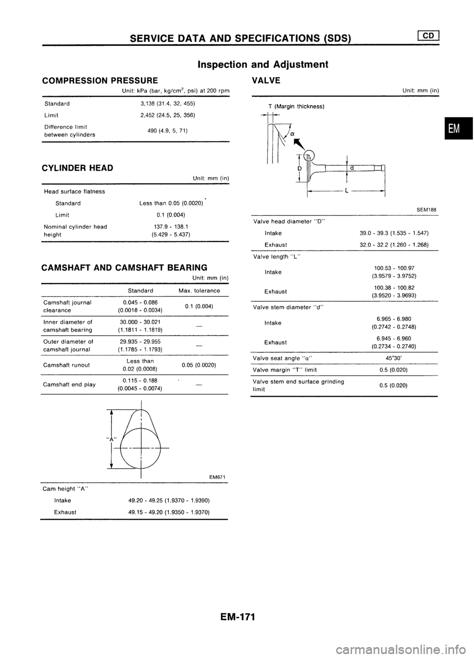
SERVICEDATAANDSPECIFICATIONS (SDS)
COMPRESSION PRESSURE Inspection
andAdjustment
VALVE
Standard
Limit
Difference limit
between cylinders
CYLINDER HEAD
Head surface flatness
Standard Limit
Nominal cylinderhead
height Unit:
kPa(bar, kg/cm
2,
psi)at
200
rpm
3,138 (31.4, 32,455)
2,452 (24.5, 25,356)
490 (4.9, 5,71)
Unit: mm(in)
Less than
0.05(0.0020)
0.1 (0,004)
137.9 -138.1
(5.429 -5.437)
T
(Margin thickness)
1t
f"~ if
Valve headdiameter "D"
Intake
Exhaust
Valve length "L" Unit:
mm(in)
SEM188
39.0 -39.3 (1.535 -1.547)
32.0 -32.2 (1,260 -1.268)
•
CAMSHAFT ANDCAMSHAFT BEARING
Camshaft journal
clearance
Inner diameter of
camshaft bearing
Outer diameter of
camshaft journal
Camshaft runout
Camshaft endplay Standard
0.045 -0.086
(0.0018 -0.0034)
30.000 -30.021
(1.1811 -1.1819)
29.935 -29.955
(1.1785 -11793)
Less than
0.02 (0.0008)
0.115 -0.188
(0.0045 -0.0074)
Unit:
mm(in)
Max. tolerance
0.1 (0.004)
0.05 (0.0020)
EM671
Intake
Exhaust
Valve stemdiameter "d"
Intake
Exhaust
Valve seatangle "u"
Valve margin
"r
limit
Valve stemendsurface grinding
limit
100.53
-100.97
(3.9579 -3.9752)
100.38 -100.82
(3.9520 -3.9693)
6.965 -6.980
(0.2742 -0.2748)
6.945 -6.960
(0.2734 -0.2740)
45°30'
0.5 (0.020)
0.5 (0.020)
Cam height "A"
Intake
Exhaust
49.20
-49.25 (1.9370 -1.9390)
49.15 -49.20 (1.9350 -1.9370)
EM-171