NISSAN ALMERA N15 1995 Service Manual
Manufacturer: NISSAN, Model Year: 1995, Model line: ALMERA N15, Model: NISSAN ALMERA N15 1995Pages: 1701, PDF Size: 82.27 MB
Page 1361 of 1701
HOWTOUSE THIS MANUAL
•
•
•
•
•
•
ALPHABETICAL
INDEXisprovided atthe end ofthis manual sothat youcan rapidly findtheitem •
and page youaresearching for.
A QUICK REFERENCE INDEX,ablack tab(e.g.
I=J;J)
is provided onthe first page. Youcanquickly
find thefirst page ofeach section bymating itto the section's blacktab.
THE CONTENTS arelisted onthe first page ofeach section .
THE TITLE isindicated onthe upper portion ofeach pageandshows thepart orsystem .
THE PAGE NUMBER ofeach section consists oftwo letters whichdesignate theparticular section
and anumber (e.g."BR-5").
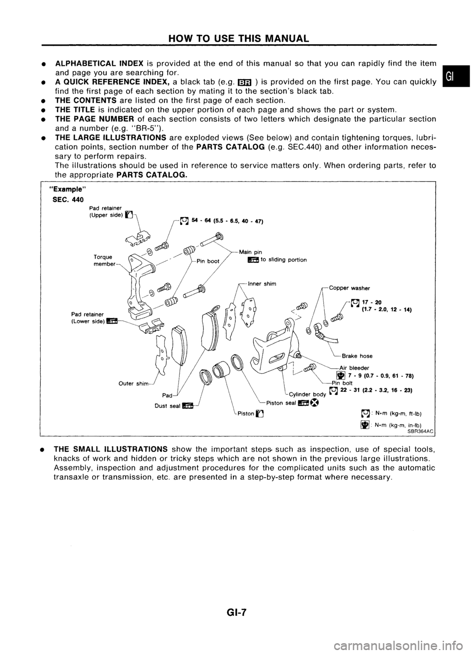
THE LARGE ILLUSTRATIONS areexploded views(Seebelow) andcontain tightening torques,lubri-
cation points, section number ofthe PARTS CATALOG (e.g.SEC.440) andother information neces-
sary toperform repairs.
The illustrations shouldbeused inreference toservice matters only.When ordering parts,referto
the appropriate PARTSCATALOG.
"Example"
SEC. 440
~~Copper washer
~ /~17-20
<~ ~~
(1.7-2.0, 12•14)
,~
'(~
,
i"::
I
cftJ ~
Brake hose
~ ~Air bleeder
V
1111
7•9 (0.7 -0.9, 61-78)
Pin bolt
~ 22-31 (2.2 -3.2, 16•23)
-Cylinder body~-~
Piston sealm~
Piston
I] ~:
N.m(kg-m, ft-Ib)
It].
N'm(kg-m, in-Ib)
SBR364AC
Outer
shim
Torque
member
Pad
retainer
(Upper side)
1]\
~ jL"J
54... 1'5•'.5, 40•
'71
/~ ~D Mainpin
/ mtosliding portion
o ~
D
~ ~
----------
Pad retainer ~
(Lower Side)m~
• THE SMALL ILLUSTRATIONS showtheimportant steps-suchasinspection, useofspecial tools,
knacks ofwork andhidden ortricky stepswhich arenotshown inthe previous largeillustrations.
Assembly, inspectionandadjustment procedures forthe complicated unitssuchasthe automatic
transaxle ortransmission, etc.arepresented inastep-by-step formatwherenecessary.
GI-7
Page 1362 of 1701
HOWTOUSE THIS MANUAL
ManualTransaxle/Transmission
Automatic Transaxle/
Transmission
Air Conditioner
Power Steering
Special Service Tools
Society ofAutomotive Engineers,
Inc.
Automatic Transmission Fluid
Drive range 1stgear
Drive range 2ndgear
Drive range 3rdgear
Drive range 4thgear
Overdrive
2nd range 2ndgear
2nd range 1stgear
1st range 2ndgear
1st range 1stgear
A/C
PIS
Tool SAE
ATF
0
1
O
2
0
3
0
4
00
2
2
2
1
1
2
1
1
•
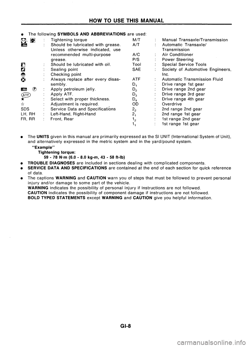
The following
SYMBOLS ANDABBREVIATIONS
areused:
to;J,
l\tI
Tightening torque M/T
IE!
Shouldbelubricated withgrease. A/T
Unless otherwise indicated,use
recommended multi-purpose
grease.
Should belubricated withoil.
Sealing point
Checking point
Always replaceafterevery disas-
sembly.
Apply petroleum jelly.
Apply ATF.
Select withproper thickness.
Adjustment isrequired.
Service DataandSpecifications
Left-Hand, Right-Hand
Front, Rear
IE!
~
@
*
1I
SDS LH, RH
FR, RR
• The
UNITS
giveninthis manual areprimarily expressed asthe SlUNIT (International SystemofUnit),
and alternatively expressedinthe metric system andinthe yard/pound system.
"Example" Tightening torque:
59 -78 N'm (6.0-8.0 kg-m, 43-58 ft-Ib)
• TROUBLE DIAGNOSES
areincluded insections dealingwithcomplicated components.
• SERVICE DATAANDSPECIFICATIONS
arecontained atthe end ofeach section forquick reference
of data.
• The captions
WARNING
and
CAUTION
warnyouofsteps thatmust befollowed toprevent personal
injury and/or damage tosome partofthe vehicle.
WARNING
indicatesthepossibility ofpersonal injuryifinstructions arenotfollowed.
CAUTION
indicatesthepossibility ofcomponent damageifinstructions arenotfollowed.
BOLD TYPED STATEMENTS
except
WARNING
and
CAUTION
giveyouhelpful information.
GI-8
Page 1363 of 1701
HOWTOREAD WIRING DIAGRAMS
Sample/Wiring Diagram-EXAMPL -
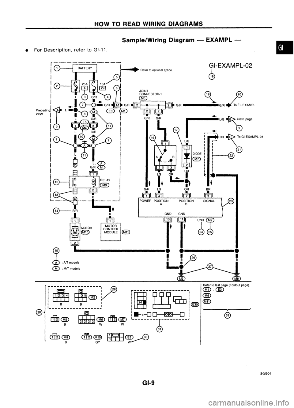
• For Description, refertoGI-11.
•
G/-EXAMPL-02
4
BA
rn
@
Aefer tolast page (Foldout page).
@.@)
@
@D
----~¥----
@
~"G~'P.g.
I
r~
BA~TO GI.EXAMPL.04
UG ....
I
1
t
I 21
':@
I
I
I
I
•
•
~
fjJ
_____ -_G/R
~oEL.EXAMPL
UNIT~
• • ~@
•
G/R
ffi
POWER POSITION POSITIONSIGNAL
A B
!-_
••~
Refer tooptional splice
r-------------------
i~
rnrcrni@)
I I
:.a-o~:
'--------~ ----
---_.
cmW5~
GY
RELAY
QID
l!4Jl
e-: ._.~~_.
III
"OWP ~~,
M
@])
MODULE@D
!
.M~--------------.L..!
.i~.-26------.'T
@ :
MfT models
!-~--~-~-~
I B B :
,------------------
ctrn
@ ~
@
lffu
@)
B WW
SGI904
GI-9
Page 1364 of 1701
Optionalsplice HOW
TOREAD WIRING DIAGRAMS
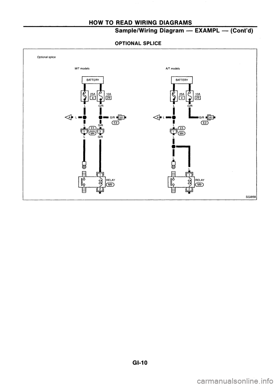
Sample/Wiring Diagram-EXAMPL -(Cont'd)
OPTIONAL SPLICE
MfT models
10A
(ffi
L G/R
I I
<&
L_.
._G/R~
I I~
L
CID
G/R
IrfJ~.~~.m
...... @)
'-II-'
L G/R
o
~l RELAY
U
@
l!:j:JJ
GI-10AfT
models
lOA
(ffi
L
I
~L_.
I
L
~CID
I~I@)
L
I
!l
~
~
n
RELAY
U
@
l!:j:JJ
SGI858
Page 1365 of 1701
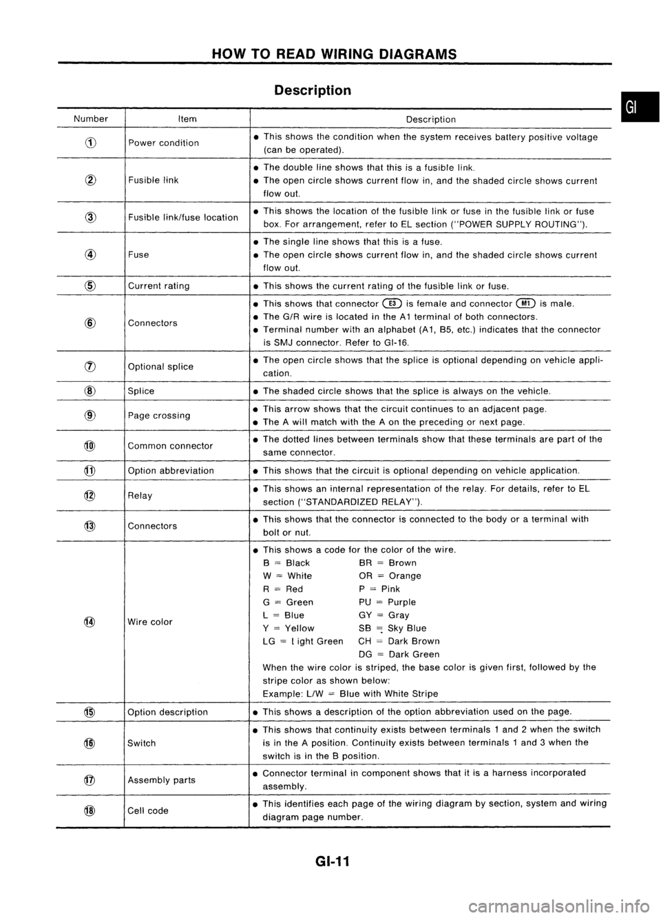
HOWTOREAD WIRING DIAGRAMS
Description
Number Item Description
CD
Power
condition •
This shows thecondition whenthesystem receives batterypositive voltage
(can beoperated) .
• The double lineshows thatthisisafusible link.
@
Fusiblelink
•The open circle shows current flowin,and theshaded circleshows current
flow out.
link/fuse location •
This shows thelocation ofthe fusible linkorfuse inthe fusible linkorfuse
box. Forarrangement, refertoEL section ("POWER SUPPLYROUTING") .
• The single lineshows thatthisisafuse.
@
Fuse
•The open circle shows current flowin,and theshaded circleshows current
flow out.
CID
Current
rating
•This shows thecurrent ratingofthe fusible linkorfuse .
• This shows thatconnector
@)
isfemale andconnector
@
ismale .
@
Connectors •
The G/R wire islocated inthe A1 terminal ofboth connectors.
• Terminal numberwithanalphabet (A1, B5, etc.) indicates thattheconnector
is SMJ connector. RefertoGI-16 .
rJ)
Optionalsplice •
The open circle shows thatthesplice isoptional depending onvehicle appli-
cation.
@
Splice •The shaded circleshows thatthesplice isalways onthe vehicle.
@
Page
crossing •
This arrow shows thatthecircuit continues toan adjacent page.
• The Awill match withtheAon the preceding ornext page .
@)
Commonconnector •
The dotted linesbetween terminals showthatthese terminals arepart ofthe
same connector.
@
Option
abbreviation •This shows thatthecircuit isoptional depending onvehicle application.
@
Relay •
This shows aninternal representation ofthe relay. Fordetails, refertoEL
section ("STANDARDIZED RELAY").
@
Connectors •
This shows thattheconnector isconnected tothe body oraterminal with
bolt ornut.
• This shows acode forthe color ofthe wire.
B
=
Black BR
=
Brown
W
=
White OR
=
Orange
R
=
Red P
=
Pink
G
=
Green PU
=
Purple
@
Wire
color L
=
Blue GY
=
Gray
Y
=
Yellow SB
=:
Sky Blue
LG
=
Light Green CH
=
Dark Brown
DG
=
Dark Green
When thewire color isstriped, thebase color isgiven first,followed bythe
stripe colorasshown below:
Example: LlW
=
Blue withWhite Stripe
@
Optiondescription •
This shows adescription ofthe option abbreviation usedonthe page.
• This shows thatcontinuity existsbetween terminals 1and 2when theswitch
@)
Switch is
inthe Aposition. Continuity existsbetween terminals 1and 3when the
switch isinthe Bposition .
@
Assembly
parts •
Connector terminalincomponent showsthatitis aharness incorporated
assembly .
@
Cell
code •
This identifies eachpage ofthe wiring diagram bysection, systemandwiring
diagram pagenumber.
GI-11
•
Page 1366 of 1701
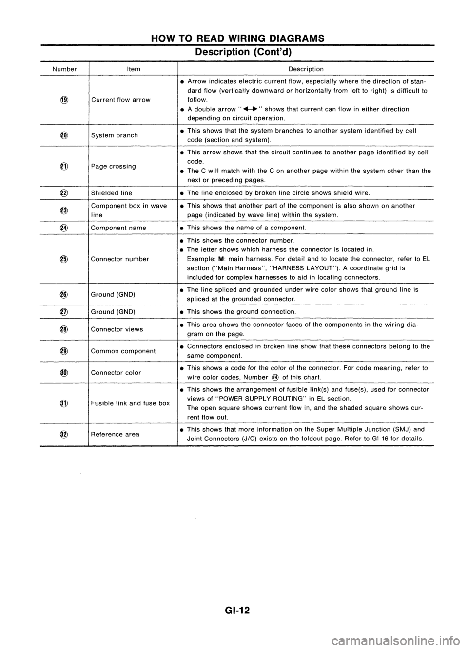
HOWTOREAD WIRING DIAGRAMS
Description (Cont'd)
Number Item Description
• Arrow indicates electriccurrentflow,especially wherethedirection ofstan-
dard flow(vertically downward orhorizontally fromlefttoright) isdifficult to
@)
Current
flowarrow follow.
• Adouble arrow" ...."shows thatcurrent canflow ineither direction
depending oncircuit operation .
@)
System
branch •
This shows thatthesystem branches toanother systemidentified bycell
code (section andsystem) .
• This arrow shows thatthecircuit continues toanother pageidentified bycell
@
code.
Page crossing
•The Cwill match withtheCon another pagewithin thesystem otherthanthe
next orpreceding pages.
@
Shieldedline •
The lineenclosed bybroken linecircle shows shieldwire.
@)
Component
boxinwave •
This shows thatanother partofthe component isalso shown onanother
line page
(indicated bywave line)within thesystem.
@
Component
name •This shows thename ofacomponent.
• This shows theconnector number.
• The letter shows whichharness theconnector islocated in.
@)
Connector
number Example:
M:main harness. Fordetail andtolocate theconnector, refertoEL
section ("MainHarness", "HARNESS LAYOUT").Acoordinate gridis
included forcomplex harnesses toaid inlocating connectors .
@
Ground
(GND) •
The linespliced andgrounded underwirecolor shows thatground lineis
spliced atthe grounded connector.
@
Ground
(GND) •
This shows theground connection.
@)
Connector
views •
This area shows theconnector facesofthe components inthe wiring dia-
gram onthe page .
@)
Common
component •
Connectors enclosedinbroken lineshow thatthese connectors belongtothe
same component.
@l
Connector
color •
This shows acode forthe color ofthe connector. Forcode meaning, referto
wire color codes, Number
@
ofthis chart.
• This shows thearrangement offusible link(s)andfuse(s), usedforconnector
@
views
of"POWER SUPPLYROUTING" inEL section.
Fusible linkand fuse box
Theopen square showscurrent flowin,and theshaded squareshowscur-
rent flow out.
@
Reference
area •
This shows thatmore information onthe Super Multiple Junction (SMJ)and
Joint Connectors
(J/C)
exists onthe foldout page.RefertoGI-16 fordetails.
GI-12
Page 1367 of 1701
HOWTOREAD WIRING DIAGRAMS
Description (Cont'd)
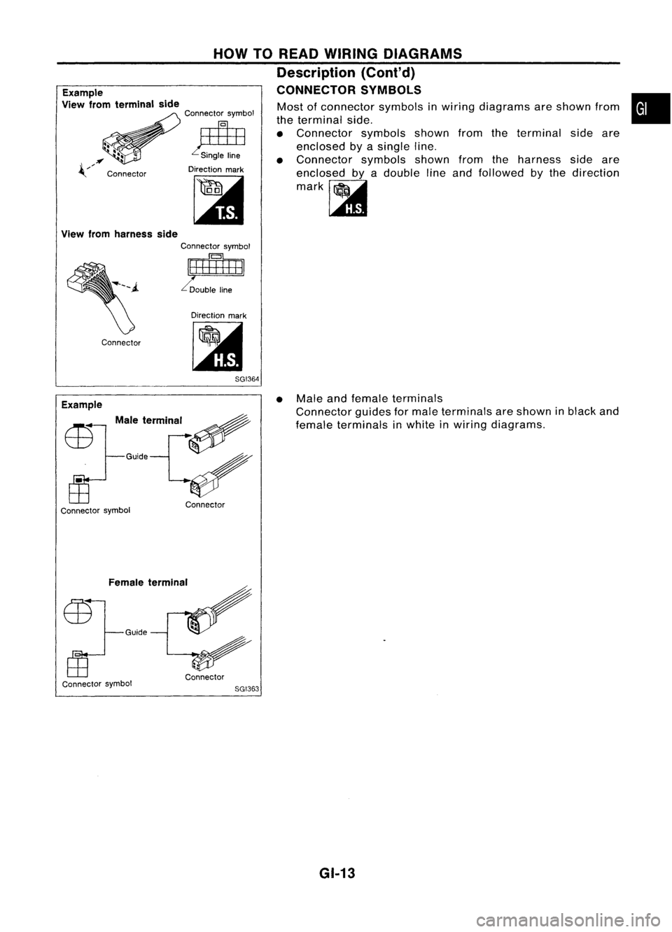
CONNECTOR SYMBOLS
Example
View fromterminal side
Connector symbol
~
Direction mark
[:it
Most
ofconnector symbolsinwiring diagrams areshown from
the terminal side.
• Connector symbolsshownfromtheterminal sideare
enclosed byasingle line.
• Connector symbolsshownfromtheharness sideare
enclosed byadouble lineand followed bythe direction
mark~
•
Direction mark
lit
Connector
View
fromharness side
Connector symbol
~I
8GI364
Male termlnar ~
G'id'V
Example
Connector symbol Connector •
Male
andfemale terminals
Connector guidesformale terminals areshown inblack and
female terminals inwhite inwiring diagrams.
Female terminal
Guide
Connector symbol Connector
8GI363
GI-13
Page 1368 of 1701
Normallyopen
HOW
TOREAD WIRING DIAGRAMS
Description (Cont'd)
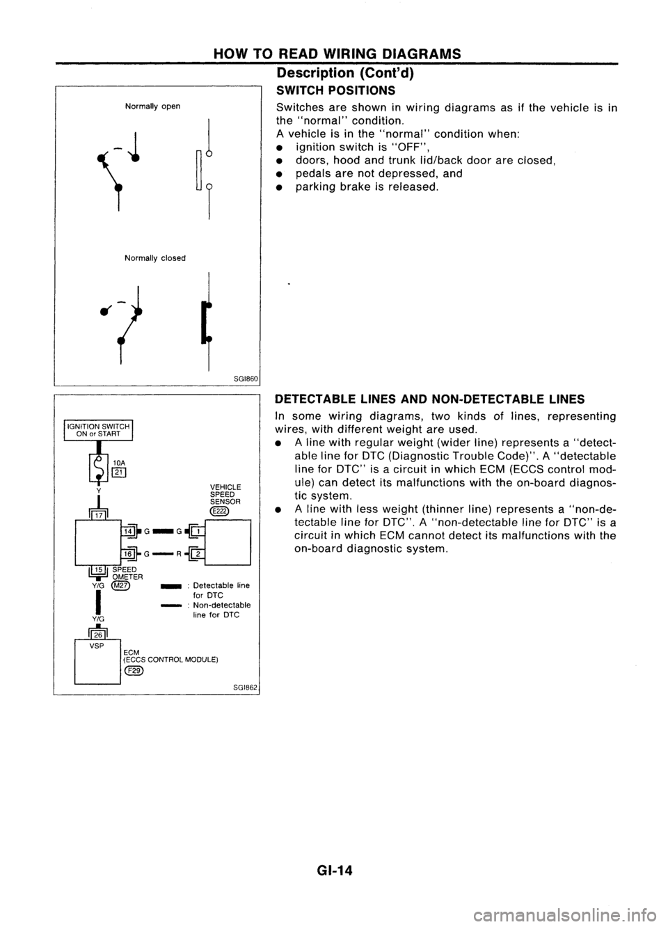
SWITCH POSITIONS
Switches areshown inwiring diagrams asifthe vehicle isin
the "normal" condition.
A vehicle isin the "normal" conditionwhen:
• ignition switchis"OFF",
• doors, hoodandtrunk lid/back doorareclosed,
• pedals arenotdepressed, and
• parking brakeisreleased.
Normally closed
5GI860DETECTABLE LINESANDNON-DETECTABLE LINES
In some wiring diagrams, twokinds oflines, representing
wires, withdifferent weightareused.
• Aline with regular weight(widerline)represents a"detect-
able lineforDTC (Diagnostic TroubleCode)".A"detectable
line forDTC" isacircuit inwhich ECM(ECCS control mod-
ule) candetect itsmalfunctions withtheon-board diagnos-
tic system.
• Aline with lessweight (thinner line)represents a"non-de-
tectable lineforDTC", A"non-detectable lineforDTC" isa
circuit inwhich ECMcannot detectitsmalfunctions withthe
on-board diagnostic system.
SGI862
_
:Detectable line
for DTC
- :Non-detectable
line forDTC
Y
~ VEHICLE
SPEED SENSOR
@
lill-G_G~
llli-G-R~
I~I
SPEED
.,=
OMETER
Y/G
@Z)
I
Y/G
[]26
VSP ECM
(ECCS CONTROL MODULE)
@)
GI-14
Page 1369 of 1701
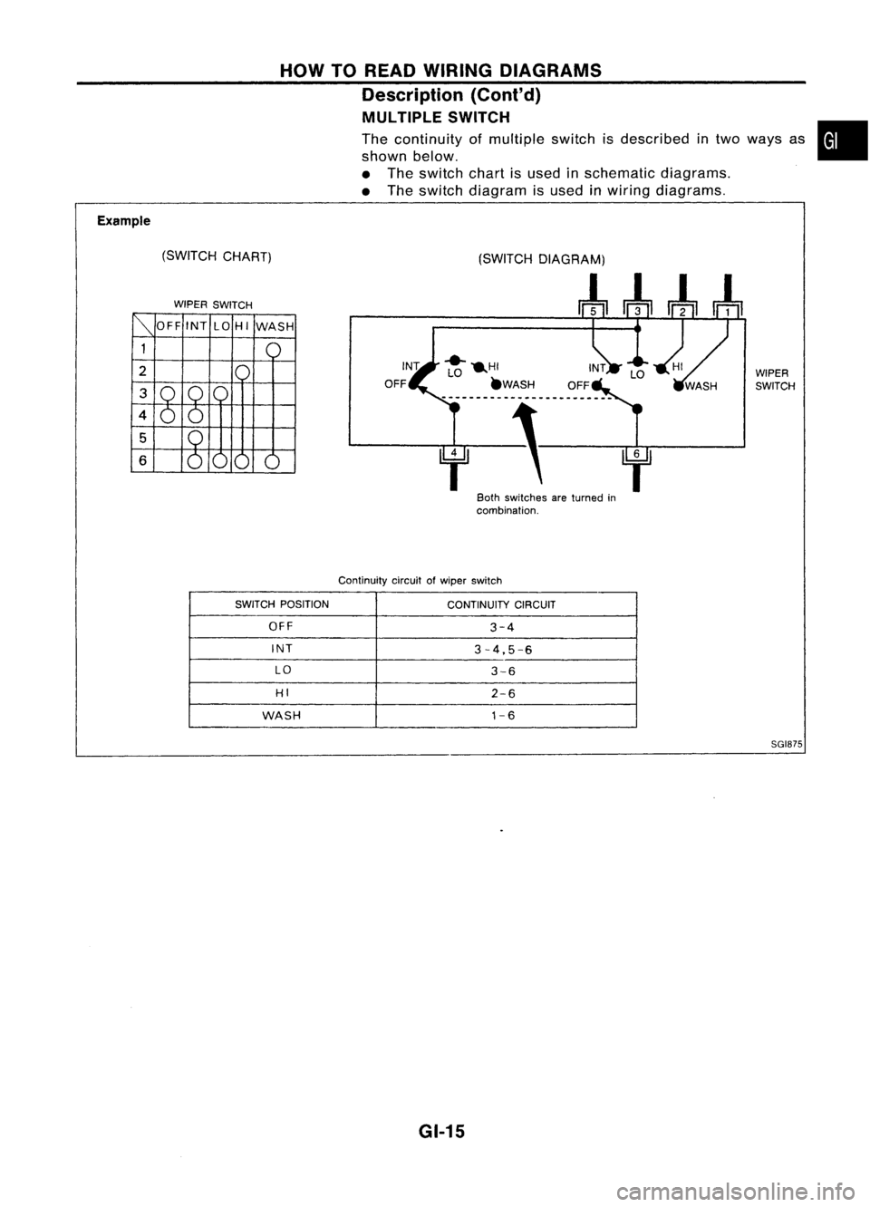
Example(SWITCHCHART)
WIPER SWITCH HOW
TOREAD WIRING DIAGRAMS
Description (Cont'd)
MULTIPLE SWITCH
The continuity ofmultiple switchisdescribed intwo ways as
shown below.
• The switch chartisused inschematic diagrams.
• The switch diagram isused inwiring diagrams.
WIPERSWITCH
f' f
80th switches areturned in
combination.
Continuity circuitofwiper switch
•
SWITCH POSITION
CONTINUITYCIRCUIT
OFF
3-4
INT
3-4,5-6
LO
3-6
HI
2-6
WASH
1-6
SGI875
GI-15
Page 1370 of 1701
HOWTOREAD WIRING DIAGRAMS
Description (Cont'd)
FOLDOUT PAGE
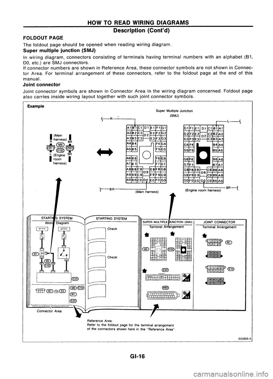
The foldout pageshould beopened whenreading wiringdiagram.
Super multiple junction (SMJ)
In wiring diagram, connectors consistingofterminals havingterminal numbers withanalphabet (81,
DO, etc.) areSMJ connectors.
If connector numbersareshown inReference Area,these connector symbolsarenotshown inConnec-
tor Area. Forterminal arrangement ofthese connectors, refertothe foldout pageatthe end ofthis
manual.
Joint connector
Joint connector symbolsareshown inConnector Areainthe wiring diagram concerned. Foldoutpage
also carries
insidewiring
layouttogether withsuch jointconnector symbols.
Example SuperMultiple Junction
(SMJ)
L----S
I
(Main
I
R harness)
@
BR
1~~_~_5 __
1~1
....... @ID .......
L (Engine BR
I
room
I
harness) AlB1Cl
01ElFIGl
A2B2 C202 E2F2G2
A3B3C3 E3F3G3
A4B4
@]
F4G4
5 B5 F55
A6B6
0
F6G6
A7B7 F77
A8B8C8 E8F8G8
09
A989C9 E9F9G9
AO BOCO DO EOFOGO Gl
FlEl 01ClBlAl
2F2E202C2B2A2
G3 F3E3 C3B3 A3
G4F4
C
B4A4
G5 F5 B5A5
G6 F6 86A6
G7F7 B7A7
G8F8 E8 C888A8
09
G9 F9E9 C989A9
GO FOEO 0 COBO AO
r-
BR
(Mainharness) (Engine
roomharness) BR----{
rDI.TI:IImP
[ill![ill]
@g)
JOINT
CONNECTOR
Terminal Arrangement
*
r::t::rrm::m:J
'M'i'
[ill]II!J ~
*
~
rll"
!! !
I
!
I II
!I
I
'J ~
~lllll!I!!lIllbV ~
SUPER
MULTIPLE UNCTION(SMJ)
Terminal Arangement
*
@)
~=fH+H=1
[II
STARTING
SYSTEM
G
SYSTEM
Diagram
~r-
[Jcheck
CJ
OCh~'
o
[J
STARTI
Wirin
@(3)
'tffB'
@)
Qfu@
@)
@
"-)-~
y
Connector Area
ReferenceArea:
Refer tothe foldout pageforthe terminal arrangement
of the connectors shownhereinthe "Reference Area".
SG1859-A
GI-16