NISSAN ALMERA N15 1995 Service Manual
Manufacturer: NISSAN, Model Year: 1995, Model line: ALMERA N15, Model: NISSAN ALMERA N15 1995Pages: 1701, PDF Size: 82.27 MB
Page 361 of 1701
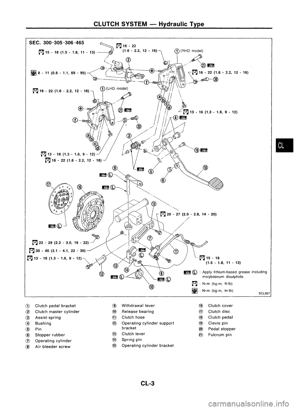
SCL667
CLUTCH
SYSTEM -Hydraulic Type
m
(bl:
Apply lithium-based greaseincluding
molybdenum disulphide.
~ :N.m (kg-m. ft-Ib)
~ :N.m (kg-m. in-Ib)
•
G)
Clutch pedalbracket
@
Clutch master cylinder
@
Assist spring
@
Bushing
@
Pin
@
Stopper rubber
(J)
Operating cylinder
@
Airbleeder screw
@
Withdrawal lever
@J
Release bearing
@
Clutch hose
@
Operating cylindersupport
bracket
@
Clutch lever
@
Spring pin
@ Operating cylinderbracket
CL-3 @
Clutch cover
@
Clutch disc
@
Clutch pedal
@
Clevis pin
@
Pedal stopper
@
Fulcrum pin
Page 362 of 1701
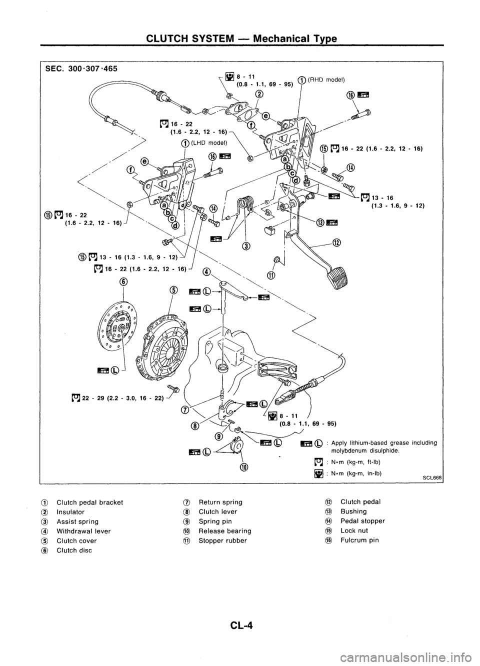
CLUTCHSYSTEM-Mechanical Type
SEC. 300'307.465
SCL668
\~
8-11
(0.8 -1.1, 69-95)
r""
@
@m
~~~ ~
/~
to.J 16-22
f
77'\
-j, ~'
, (1.6.2.2,12-16)~ ~
M-
.
Of~ ':,
,/ I
r';, ~~
I'
@
to.J 16•22 (1.6 -2.2, 12•16)
/ fA'l
@m~
a!',~~
I
,/' ~~ {l
,-0 ~
be\.\~':~ @
<
01Q'?0'J:l'e..------ ,
d~~
~;, 1
v,~
~, ~i,:
1r
J
~m
to.J13-16
c
I~..--.......
~JO
a,
',@/ :'~' ~ (1.3•1.6, 9-12)
@
to.J 16-22 ~
be c
_1
L~---- .~
.Jl
(1.6 -2.2, 12-16)
'~d' ~
C1J.~,
@m
'm (
@ ,
@
to.J 13-16 (1.3 •1.6, 9•12) .~. ~
I
to.J 16-22 (1.6 -2.2, 12-16)
@~ ~
@ ~~@
m(Q .
-m~.
m(Q ~
~h
<:
(7\I~ ~ .~
\ ~J;i::::;~
l"J" -
29 (2.2 -3.0,
1.-
22)1>
0~~
~ ¥:11)
@-..........t>'"l(0.8-1.1,69-95)
/l~~
~ ~I!C!
'001""00
m
(Q
molybdenumdisulphide.
Iiii\ .
[OJ;
N.m (kg-m, ft-lb)
~
IjJ;N'm (kg-m, in-Ib)
G)
Clutch pedalbracket
(1)
Return
spring @
Clutch pedal
@
Insulator
@
Clutch lever
@
Bushing
@
Assist spring
@
Spring pin
@
Pedal stopper
@
Withdrawal lever
@J
Release
bearing
@
Lock nut
@
Clutch cover
@
Stopper rubber
@
Fulcrum pin
@
Clutch disc
CL-4
Page 363 of 1701
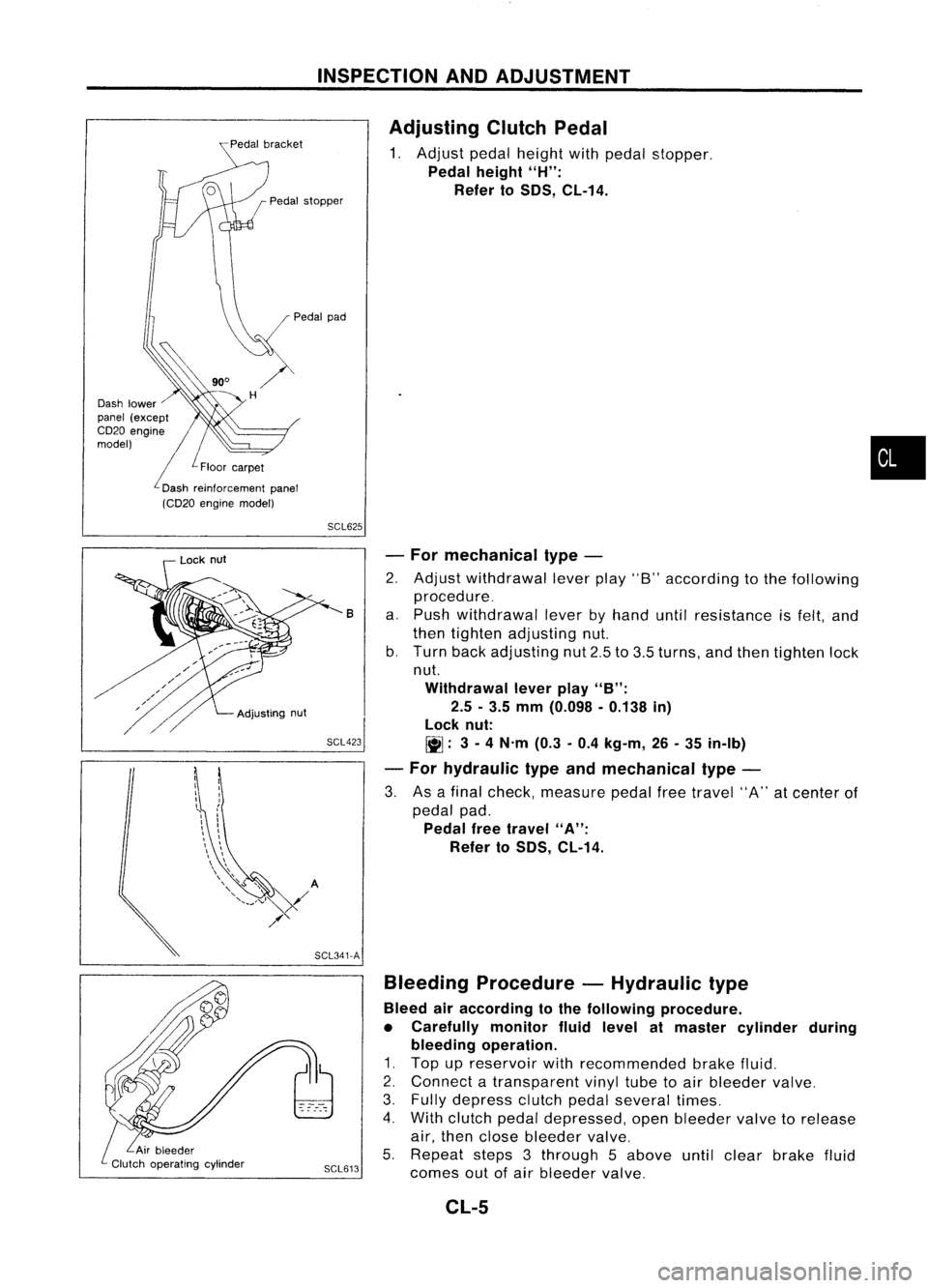
INSPECTIONANDADJUSTMENT
Pedal stopper
Dash lower
panel (except
CD20 engine //
model)
/L
Floor car-pet
L
Dash reinforcement panel
(CD20 engine model)
Adjusting
ClutchPedal
1. Adjust pedalheight withpedal stopper.
Pedal height
"H":
Refer to
50S,
CL-14.
•
SCL625
SCL423 -
For mechanical type-
2. Adjust withdrawal leverplay"8"according tothe following
procedure_
a. Push withdrawal leverbyhand untilresistance isfelt, and
then tighten adjusting nut.
b. Turn backadjusting nut2.5to3.5 turns, andthen tighten lock
nut.
Withdrawal leverplay
"B":
2.5 -3.5 mm (0.098 -0.138 in)
lock nut:
~: 3-
4 N'm (0.3-0.4 kg-m, 26-35 in-Ib)
- For hydraulic typeandmechanical type-
3. Asafinal check, measure pedalfreetravel "A"atcenter of
pedal pad.
Pedal freetravel
"A":
Refer to
50S,
CL-14.
B
Bleeding Procedure -Hydraulic type
Bleed airaccording tothe following procedure.
• Carefully monitorfluidlevel atmaster cylinder during
bleeding operation.
1. Top upreservoir withrecommended brakefluid.
2. Connect atransparent vinyltubetoair bleeder valve.
3. Fully depress clutchpedalseveral times.
4. With clutch pedaldepressed, openbleeder valvetorelease
air, then close bleeder valve.
5. Repeat steps3through 5above untilclear brake fluid
SCL613
comesoutofair bleeder valve.
SCL341-A
Adjusting
nut
Lock
nut
CL-5
Page 364 of 1701
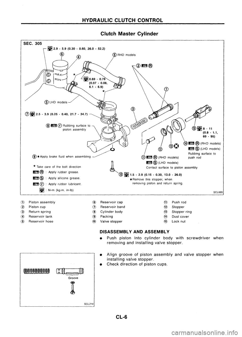
HYDRAULICCLUTCHCONTROL
Clutch Master Cylinder
SEC. 305
SCL669
~
2.9 •5.9 (0.30 •0.60, 26.0•52.2)
@
@
m
CD
Rubbing surfaceto
piston assembly
@LHD
models
m @:Apply silicone grease,
m
CD:
Apply rubber lubricant.
Iil :
N.m (kg-m. in-Ib)
CD
/
(1), ~
1'.
~'. ~". @liJa-
11
( ~I'
(08.'.1,
,<
I
~f
/@O@I1I!@(A':o'::"'1
~ @
m@(LHDmodels)
Rubbing surfaceto
@.
Apply brakefluidwhen assembling.
(jJ)
m @(RHD models) pushrod
~ m@(LHD models)
*
Take careofthe bolt direction Contactsurfacetopiston assembly
m@ :Apply rubber grease.
@~
1.5-2.9 (0.15 -0.30, 13.0-26.0)
• Remove thisstopper, when
removing pistonandreturn spring.
(j)
~
2.5 -3.9 (0.25 -0.40, 21.7-34.7)
(1)
Piston assembly
@
Reservoir
cap
@
Piston cup
(])
Reservoir
band
@
Return spring
@
Cylinder body
@
Reservoir
tank
@
Packing
@
Reservoir hose
@)
Valve stopper
@
Push rod
@
Stopper
@
Stopper ring
@
Dustcover
@
Lock nut
DISASSEMBLY ANDASSEMBLY
• Push piston intocylinder bodywithscrewdriver when
removing andinstalling valvestopper.
• Align groove ofpiston assembly andvalve stopper when
installing valvestopper.
• Check direction ofpiston cups.
c;D.=:
=.J3@
Groove
SCL214 CL-6
Page 365 of 1701
HYDRAULICCLUTCHCONTROL
Clutch Master Cylinder (Cont'd)
INSPECTION
Check thefollowing items,andreplace ifnecessary.
• Rubbing surfaceofcylinder andpiston, foruneven wear,
rust ordamage
• Piston withpiston cup,forwear ordamage
• Return spring, forwear ordamage
• Dust cover, forcracks, deformation ordamage
• Reservoir, fordeformation ordamage
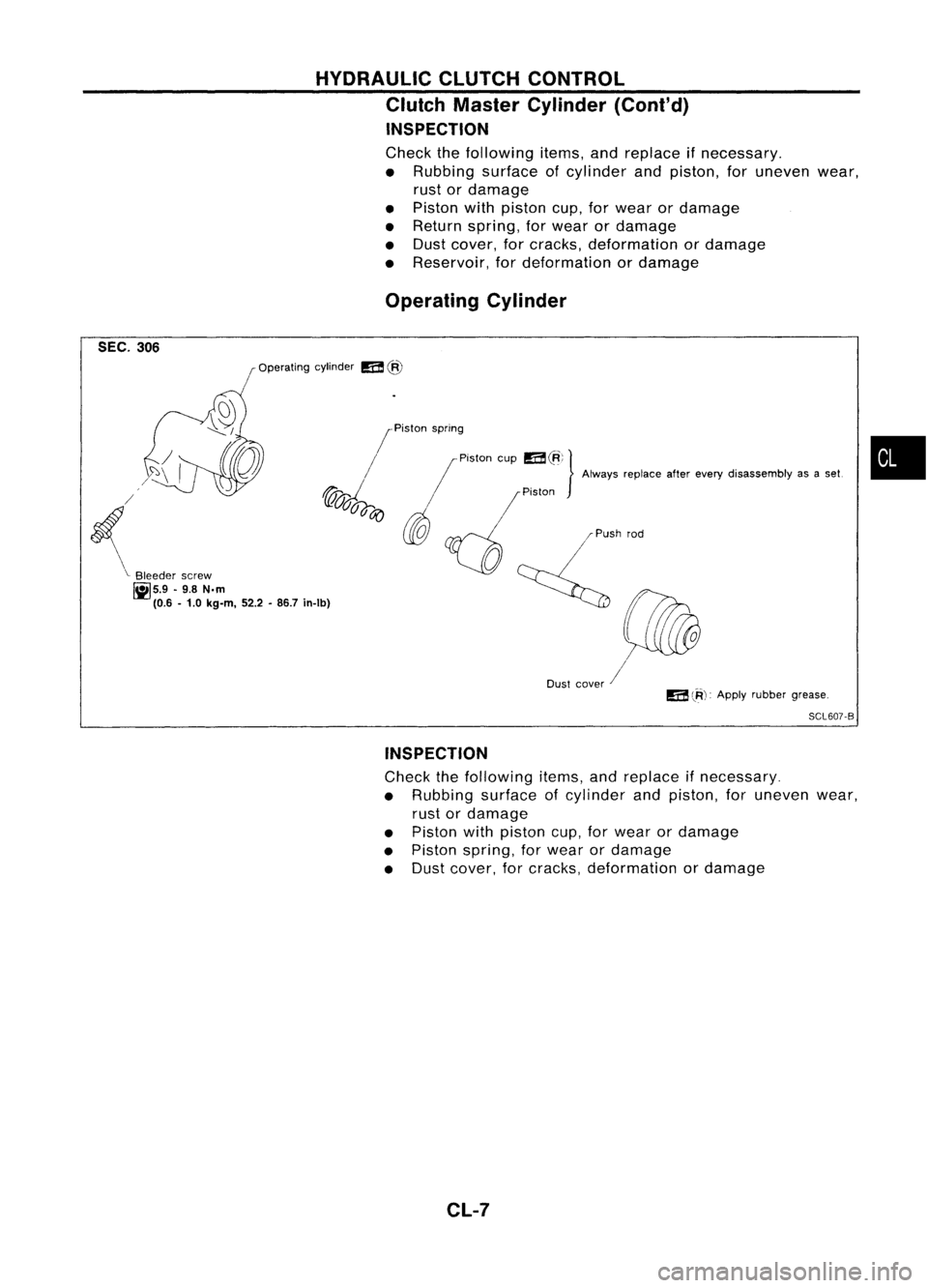
Operating Cylinder
SEC. 306
Operatingcylinder
m
@
•
/
Piston spring ,
/ I
Piston cup
m~;}
Alwaysreplace afterevery disassembly asaset.
~d /
/Piston
~ti)
d
~ Q
~,""d
(il@
Dust cover /
J
7:\
I
{
'c
Bleeder screw
IiIS.9 -9.8 N.m .
(0.6 -1.0 kg-m, 52.2-86.7 In-Ib)
m
lR):
Apply rubber grease.
SCL607-B
INSPECTION
Check thefollowing items,andreplace ifnecessary.
• Rubbing surfaceofcylinder andpiston, foruneven wear,
rust ordamage
• Piston withpiston cup,forwear ordamage
• Piston spring, forwear ordamage
• Dust cover, forcracks, deformation ordamage
CL-7
Page 366 of 1701
HYDRAULICCLUTCHCONTROL
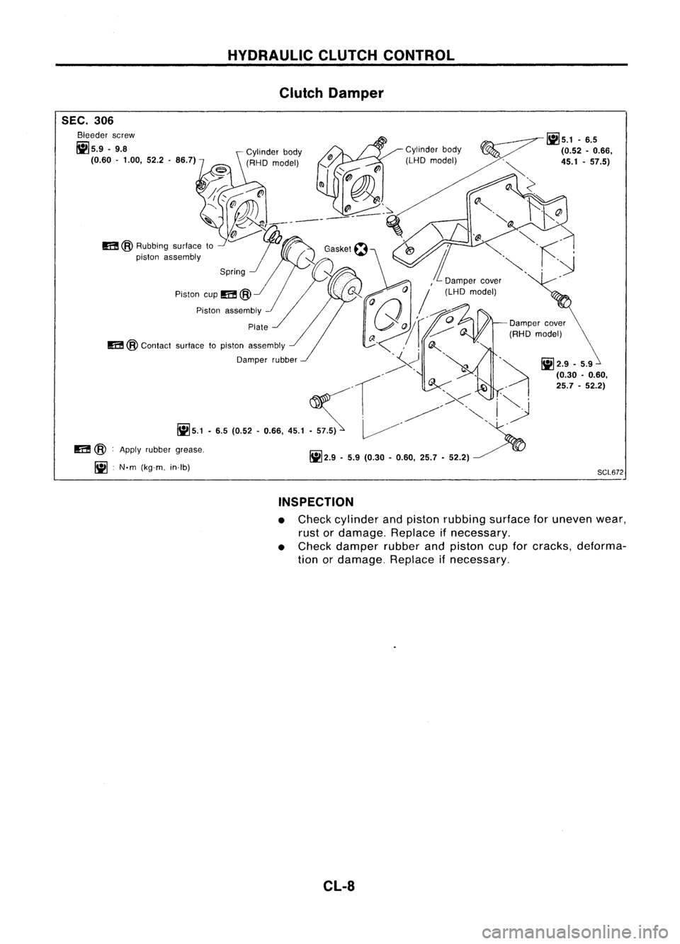
Clutch Damper
SEC. 306
Bleeder screw
1i15.9 -9.8
(0.60 -1.00, 52.2.86.7)
m
@Rubbing surfaceto
piston assembly
Piston cup
m
@
J'
Piston assembly
m
@
Contact surfacetopiston assembly
Damper rubber~
m
@:Apply rubber grease.
II] :N'm (kg-m. in-Ib) Cylinder
body
(LHD model)
11]5.1
-6.5
(0.52 -0.66,
45.1 -57.5)
- Damper cover
(RHD model)
II]
2.9 -5.9
(0.30 -0.60,
25.7 -52.2)
SCL672
INSPECTION
• Check cylinder andpiston rubbing surfaceforuneven wear,
rust ordamage. Replaceifnecessary.
• Check damper rubberandpiston cupforcracks, deforma-
tion ordamage. Replaceifnecessary.
CL-8
Page 367 of 1701
CLUTCHRELEASE MECHANISM
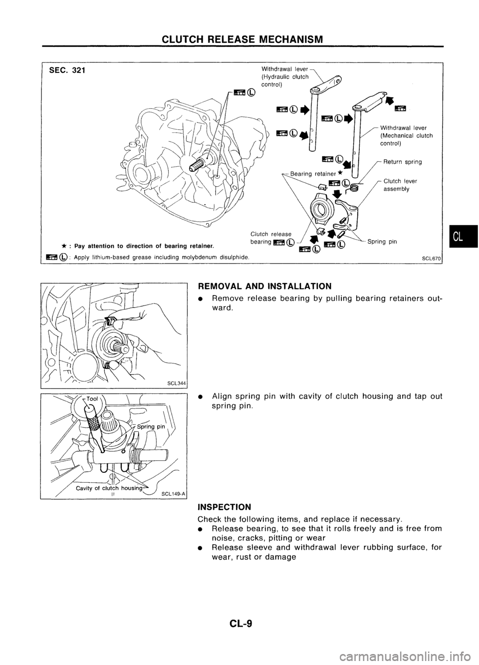
SEC. 321
* :
Pay attention todirection ofbearing retainer.
m
(Q: Apply lithium-based greaseincluding molybdenum disulphide. Withdrawal
lever
(Hydraulic clutch
control)
Springpin
SCL670
•
REMOVAL ANDINSTAllATION
• Remove releasebearing bypulling bearing retainers out-
ward.
• Align spring pinwith cavity ofclutch housing andtapout
spring pin.
INSPECTION
Check thefollowing items,andreplace ifnecessary.
• Release bearing, tosee that itrolls freely andisfree from
noise, cracks, pittingorwear
• Release sleeveandwithdrawal leverrubbing surface, for
wear, rustordamage
CL-9
Page 368 of 1701
CLUTCHRELEASE MECHANISM
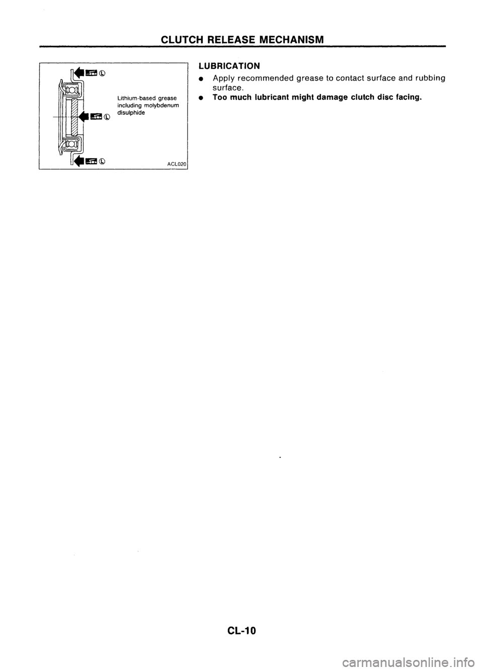
LUBRICATION
Lithium-based grease
including molybdenum
disulphide
ACL020•
•
Apply
recommended greasetocontact surface andrubbing
surface.
Too much lubricant mightdamage clutchdiscfacing.
CL-10
Page 369 of 1701
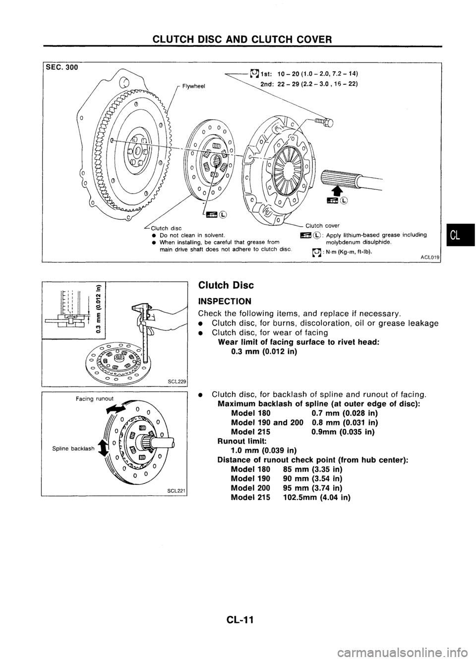
CLUTCHDISCANDCLUTCH COVER
~1st: 10-20(1.0-2.0,7.2-14)
2nd: 22-29 (2.2 -3.0 ,16 -22)
ACL019
SEC.
300
o
Clutchdisc
• Do not clean insolvent.
• When installing, becareful thatgrease from
main drive shaft doesnotadhere toclutch disc. Clutch
cover
m
(iJ:
Apply lithium-based greaseincluding
molybdenum disulphide.
~ :N'm (Kg-m, ft-Ib).
•
SCL221 Clutch
Disc
INSPECTION
Check thefollowing items,andreplace ifnecessary.
• Clutch disc,forburns, discoloration, oilorgrease leakage
• Clutch disc,forwear offacing
Wear limitoffacing surface torivet head:
0.3 mm (0.012 in)
• Clutch disc,forbacklash ofspline andrunout offacing.
Maximum backlashofspline (atouter edgeofdisc):
Model 180 0.7mm (0.028 in)
Model 190
and 200 0.8mm (0.031 in)
Model 215 0.9mm(0.035in)
Runout limit:
1.0 mm (0.039 in)
Distance ofrunout checkpoint(from hubcenter):
Model 180
85mm (3.35 in)
Model 190
90mm (3.54 in)
Model 200
95mm (3.74 in)
Model 215102.5mm (4.04in)
CL-11
Page 370 of 1701
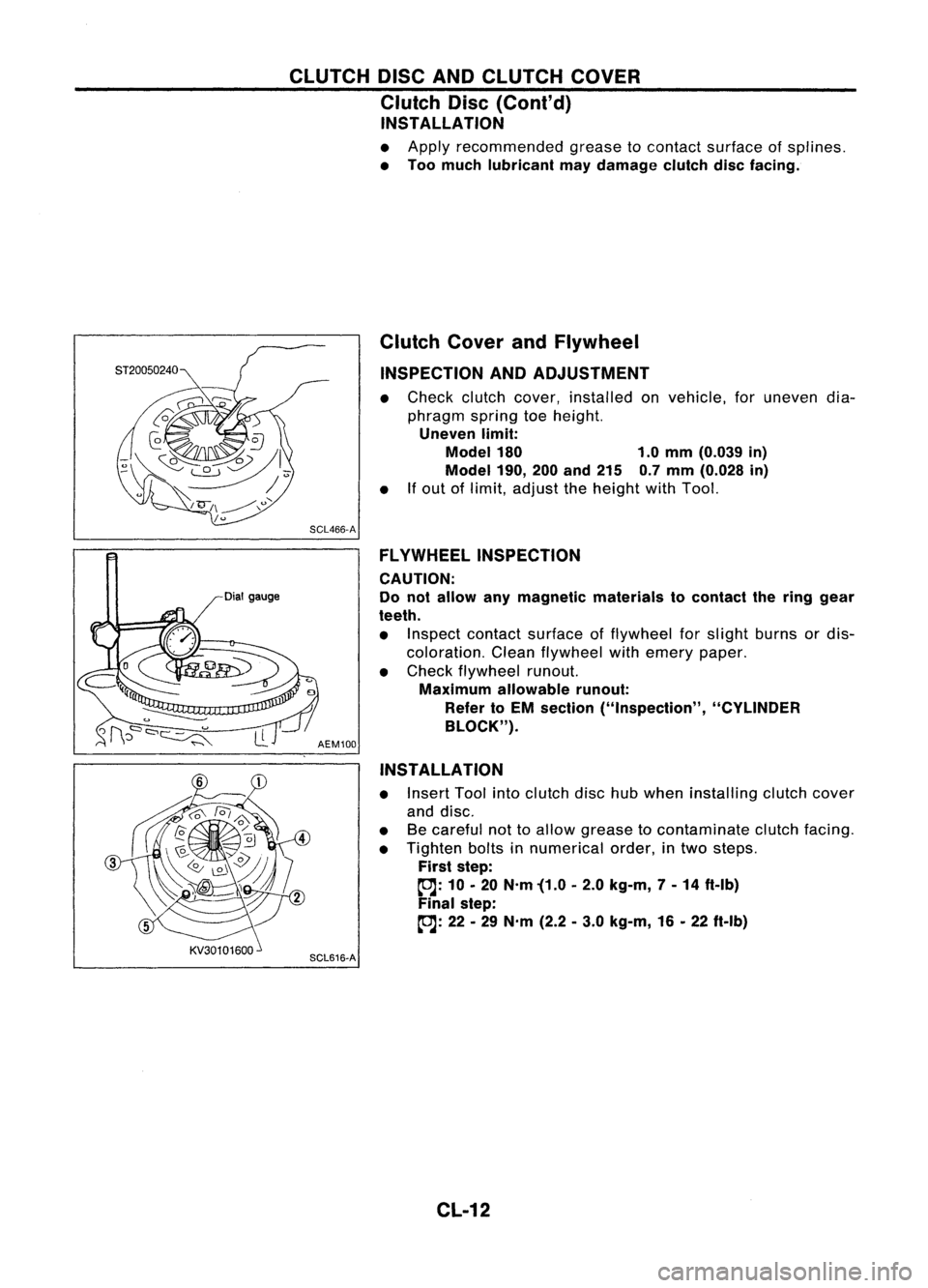
CLUTCHDISCANDCLUTCH COVER
Clutch Disc(Cont'd)
INSTALLATION
• Apply recommended greasetocontact surface ofsplines.
• Too much lubricant maydamage clutchdiscfacing.
Dial gauge Clutch
CoverandFlywheel
INSPECTION ANDADJUSTMENT
• Check clutchcover, installed onvehicle, foruneven dia-
phragm springtoeheight.
Uneven limit:
Model 180 1.0mm (0.039 in)
Model 190,
200and 215 0.7mm (0.028 in)
• Ifout oflimit, adjust theheight withTool.
SCL466-A FLYWHEEL INSPECTION
CAUTION:
Do not allow anymagnetic materials tocontact thering gear
teeth.
• Inspect contact surface offlywheel forslight burns ordis-
coloration. Cleanflywheel withemery paper.
• Check flywheel runout.
Maximum allowable runout:
Refer toEM section ("Inspection", "CYLINDER
BLOCK").
AEM100
INSTALLATION
• Insert Toolintoclutch dischubwhen installing clutchcover
and disc.
• Becareful nottoallow grease tocontaminate clutchfacing.
• Tighten boltsinnumerical order,intwo steps.
First step:
~: 10•20 N'm '(1.0 •2.0 kg-m, 7-14 ft-Ib)
Final step:
~: 22•29 N'm (2.2•3.0 kg-m, 16•22 ft-Ib)
SCL616-A
CL-12