NISSAN ALMERA N15 1995 Service Manual
Manufacturer: NISSAN, Model Year: 1995, Model line: ALMERA N15, Model: NISSAN ALMERA N15 1995Pages: 1701, PDF Size: 82.27 MB
Page 401 of 1701
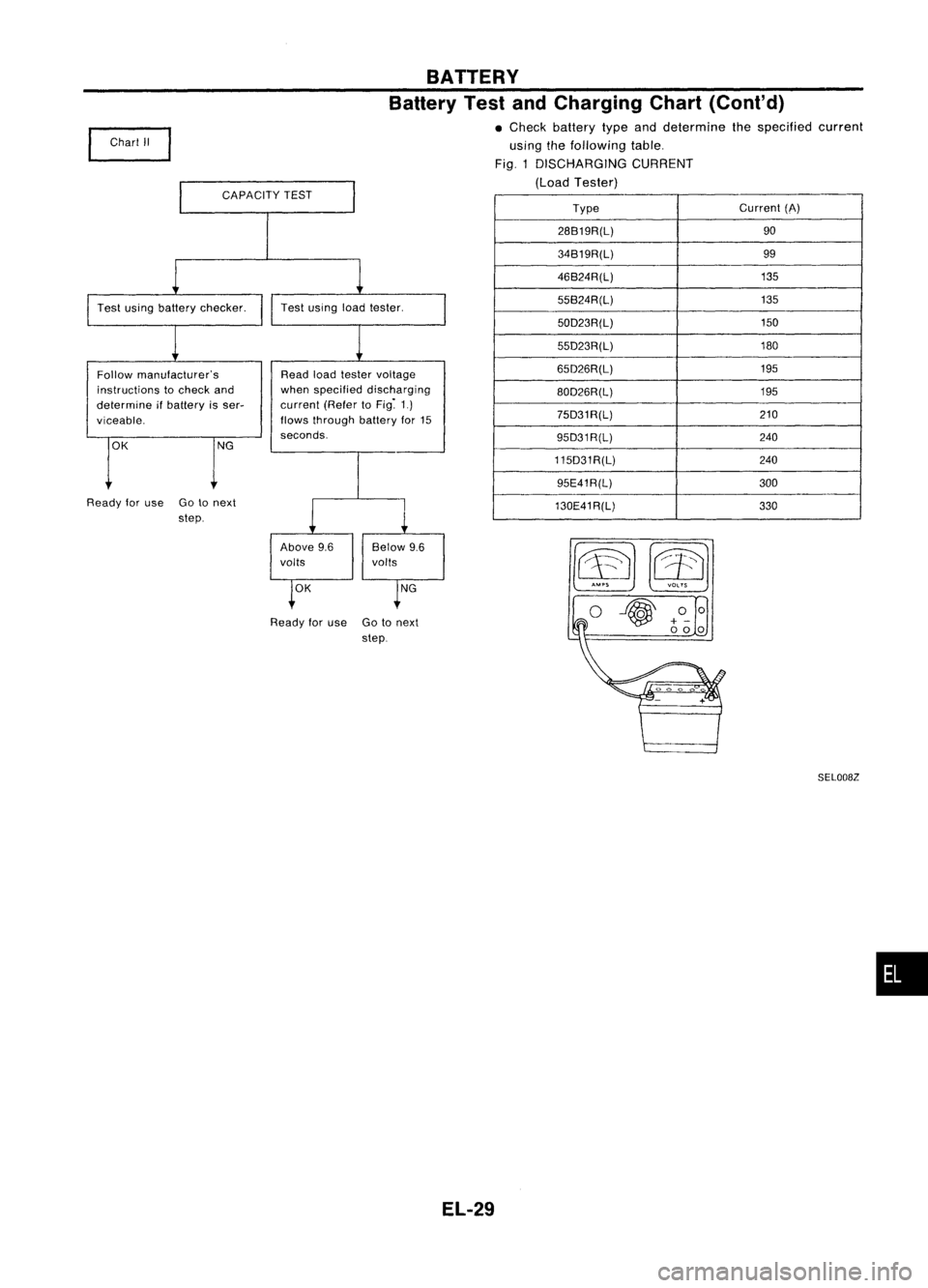
CAPACITYTEST BATTERY
Battery TestandCharging Chart(Cont'd)
• Check battery typeanddetermine thespecified current
using thefollowing table.
Fig. 1DISCHARGING CURRENT
(Load Tester)
~m o~
Type
Current
(A)
28B19R(L) 90
34B19R(L) 99
46B24R(L) 135
55B24R(L) 135
50D23R(L) 150
55D23R(L) 180
65D26R(L) 195
80D26R(L) 195
75D31R(L) 210
95D31R(L) 240
115D31R(L) 240
95E41R(L) 300
130E41R(L) 330
Test
using loadtester.
OK NG
Read
loadtester voltage
when specified discharging
current (RefertoFig~ 1.)
flows through batteryfor15
seconds.
Above 9.6 Below9.6
volts volts
Ready foruse Gotonext
step.
Chart
II
OK NG
Follow
manufacturer's
instructions tocheck and
determine ifbattery isser-
viceable,
Ready foruse Gotonext
step.
SEL008Z
•
EL-29
Page 402 of 1701
BATTERY
Battery TestandCharging Chart(Cont'd)
I
A: SLOW CHARGE
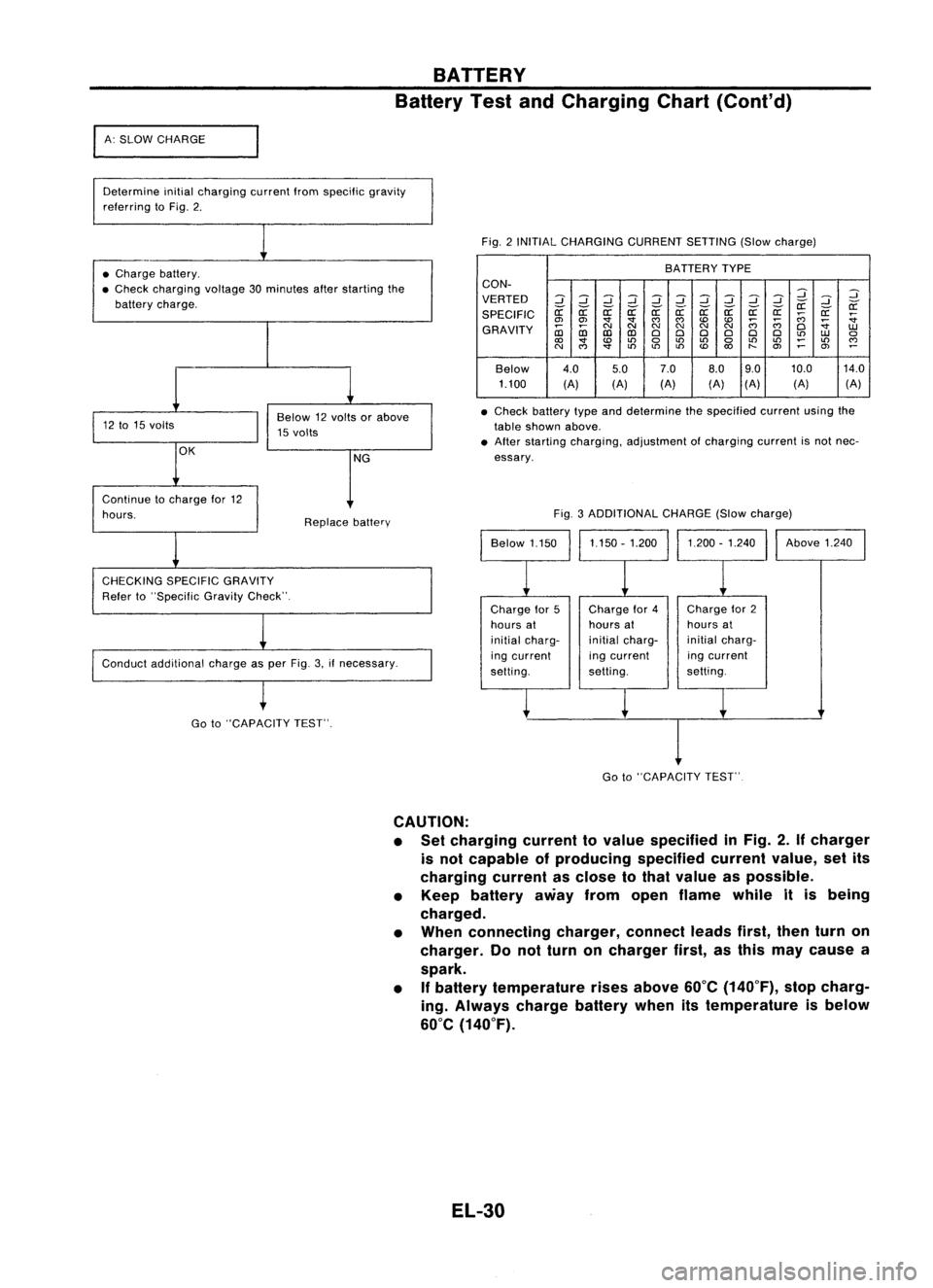
Determine initialcharging currentIromspecilic gravity
relerring toFig. 2.
Fig.2INITIAL CHARGING CURRENTSETTING(Slowcharge)
• Charge battery.
• Check charging voltage30minutes afterstarting the
battery charge. BATTERY
TYPE
CON-
VERTED
2
::J
2
::J
::J
2
::J
2
::J
::J
2
2
::J
if ifif if if
r:r:
if
SPECIFIC
r:r:
r:r: r:r:r:r:r:r:
;;;
r:r:
:;
en en
'
""""
;;;;;;
:;
GRAVITY
~
NNN
NN
N
0
1.U
CD CDCDCD
000 000
to
1.U
0
<0
'
0
to
LO
0
LOLO
~
LO
""
N
""
'
toto
LO
<0
"-
en
~
en
~
Below 4.0
5.07.0
8.09.0 10.0
14.0
1.100 (A)(A)(A) (A)(A)
(A) (A)
• Check battery typeanddetermine thespecified currentusingthe
table shown above.
• After starting charging, adjustment ofcharging currentisnot nec-
essary.
Conduct additional chargeasper Fig. 3.ifnecessary. Fig.
3ADDITIONAL CHARGE(Slowcharge)
Continue
tocharge lor12
hours.
CHECKING SPECIFICGRAVITY
Reier to"Specilic GravityCheck". Replace
battery
Chargefor5
hours at
initial charg-
ing current
selting. Charge
lor4
hours at
initial charg-
ing current
setting. Charge
lor2
hours at
initial charg-
ing current
setting. Above
1.240
Go to"CAPACITY TEST".
I
Go to"CAPACITY TEST"
CAUTION:
• Set charging currenttovalue specified inFig. 2.
If
charger
is not capable ofproducing specifiedcurrentvalue,setits
charging currentasclose tothat value aspossible.
• Keep battery awayfromopen flame whileitis being
charged.
• When connecting charger,connectleadsfirst,thenturnon
charger. Donot turn oncharger first,asthis may cause a
spark.
• If
battery temperature risesabove 60°C(140°F), stopcharg-
ing. Always chargebatterywhenitstemperature isbelow
60°C (140°F).
EL-30
Page 403 of 1701
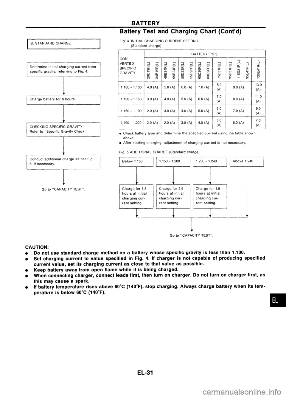
•Check battery typeanddetermine thespecified currentusingthetable shown
above .
• After starting charging, adjustment ofcharging currentisnot necessary.
BATTERY
Battery TestandCharging Chart(Cont'd)
BATTERY TYPE
CON-
VERTED
::J::J
~::J
::J
::J::J ::J ::J
::J
:J
:J
~
SPECIFIC
er:-
er:-
a:
er:-er:- er:-er:- er:- er:- er:-er:-
a:
;:;:;
a:
:;
0> 0> '1"'1"
(')
(')
to to
;:;:;
~
:;
GRAVITY
coco
C'J
C'J C'J
C'JC'J
C'J
(')
D
UJ
co co
DDD D D
D
L!)
UJ
a
to
L!)
a
L!)
L!)
a
L!)
L!)
~
L!)
~
C'J
(')
'1"
L!)
L!)L!)
to
O>
~
OJ
1.100 -1.130 4.0(A) 5.0(A) 60(A) 7.0(A) 8.0
130
(A) 90
(A)
(A)
1.130 -1160 30(Al 4.0(Al 5.0
(A) 6.0(A) 7.0
11.0
(A) 8.0
(A)
(A)
1.160 -1.190 2.0(A) 3.0(Al 4.0
(A)
5.0(Al 6.0
7.0(A) 9.0
(A) (A)
1.190 -1.220 2.0(A) 2.0(A) 3.0(A) 4.0
(A) 5.0
7.0
(A) 5.0
(A)
(A)
Fig. 5ADDITIONAL CHARGE(Standard charge)
Above1240
1.200 -1.240
1.150 -1.200
Below 1.150
Fig.
4INITIAL CHARGING CURRENTSETTING
(Standard charge)
Determine initialcharging currentfrom
specific gravity,referring toFig. 4.
Charge batteryfor8hours.
CHECKING SPECIFICGRAVITY
Refer to"Specific GravityCheck".
Conduct additional chargeasper Fig.
5, ifnecessary.
I
B: STANDARD CHARGE
Go to"CAPACITY TEST". Charge
for3.5
hours atinitial
charging cur-
rent setting. Charge
for2.5
hours atinitial
charging cur-
rent setting. Charge
for1.5
hours atinitial
charging cur-
rent setting.
I
Go to"CAPACITY TEST".
CAUTION:
• Donot use standard chargemethod onabattery whosespecific gravityisless than 1.100.
• Set charging currenttovalue specified inFig. 4.Ifcharger isnot capable ofproducing specified
current value,setitscharging currentasclose tothat value aspossible.
• Keep battery awayfromopen flame whileitis being charged.
• When connecting charger,connectleadsfirst,thenturnoncharger. Donot turn oncharger first,as
this may cause aspark.
• Ifbattery temperature risesabove 60°C(140°F), stopcharging. Alwayschargebatterywhenitstem-
perature isbelow 60°C(140°F).
•
EL-31
Page 404 of 1701
I
C: QUICK CHARGE
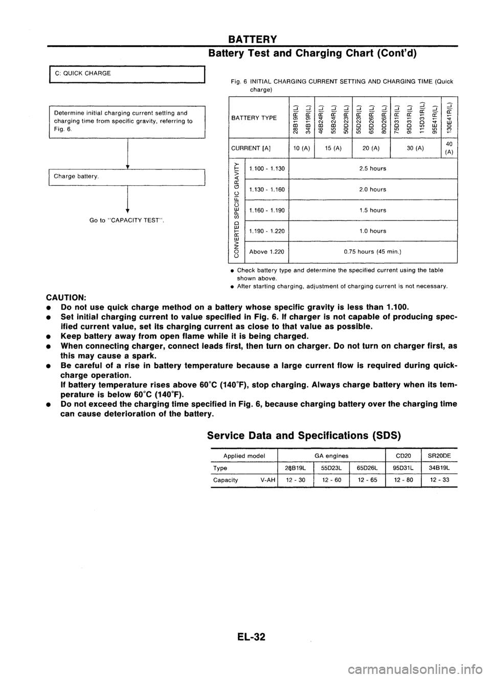
Determine initialcharging currentsettingand
charging timefrom specific gravity,referring to
Fig. 6.
I
Charge battery.
Goto"CAPACITY TEST".
BATTERY
Battery TestandCharging Chart(Cont'd)
Fig. 6INITIAL CHARGING CURRENTSETTINGANDCHARGING TIME(Quick
charge)
:::J:::J:::J:::J :::J:::J:::J
d dd
:::J
:::J :::J
~ ~
SA TTERY TYPE
~
~ ~~~~ ~a: a:a:
;;:;
~
~
0>
0>
""
""
C')
C')
CDCD
;;:;
;;:;
~
co co
C\I
N
C\I
N
C\I
N
Cl
W
D:l D:l
ClCl ClCl ClCl
L()
W
0
to
""
CD
L()
0
L()
L()
0
L()
L()
;:
L()
~
N
C')
""
L()
L()L()
CD
to
t-
O>
0>
CURRENT [A]10(A) 15(A) 20(A) 30(A) 40
(A)
>-
I-
1.100 -1.130 2.5
hours
:>
a:
(!J 1.130 -1.160 2.0
hours
0
u::
U
w
1.160 -1.190 1.5hours
0-
w
Cl
w
1.190 -1.220 1.0hours
I-
a:
w
>
z
0
Above 1.220 0.75
hours (45min.)
0
• Check battery typeanddetermine thespecified currentusingthetable
shown above.
• After starting charging, adjustment ofcharging currentisnot necessary.
CAUTION: • Donot use quick charge method onabattery whosespecific gravityisless than 1.100.
• Set initial charging currenttovalue specified inFig. 6.Ifcharger isnot capable ofproducing spec-
ified current value,setitscharging currentasclose tothat value aspossible.
• Keep battery awayfromopen flame whileitis being charged.
• When connecting charger,connectleadsfirst,thenturnoncharger. Donot turn oncharger first,as
this may cause aspark.
• Becareful ofarise inbattery temperature becausealarge current flowisrequired duringquick-
charge operation.
If
battery temperature risesabove 60°C(140°F), stopcharging. Alwayschargebatterywhenitstem-
perature isbelow 60°C(140°F).
• Donot exceed thecharging timespecified inFig. 6,because charging batteryoverthecharging time
can cause deterioration ofthe battery.
Service DataandSpecifications (SOS)
Applied model GA
engines CD20SR20DE
Type 26S19L
55D23L65D26L 95D31L
34S19L
Capacity V-AH
12-30 12
-60 12-65 12-80 12
-33
EL-32
Page 405 of 1701
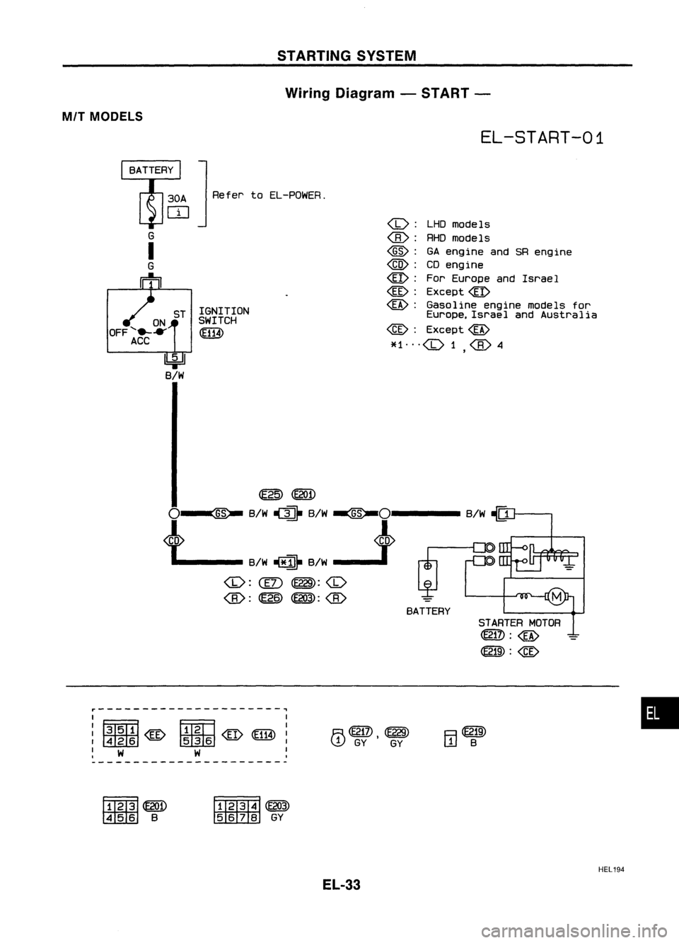
STARTINGSYSTEM
Wiring Diagram -START -
MIl MODELS
EL-START-01
U:i=ll
B/W
ON
OFF
'e- .....
ACC
:J
Refer to
EL-POWEA.
ST IGNITION
SWITCH
~
(1):
LHOmode 1s
@:
RHOmodels
@:
GAeng ine and SReng ine
@:
CDengine
@: ForEurope andIsrae 1
@:
Except@
~: Gasoline enginemodels for
Europe, IsraelandAustralia
@:
Except~
*1"'(1)1 @4
,
~~
O~ B/W~ B/W~Ol -B/W
-(Q
LB/W~B/W.J
~:
@: ~
~:@
BATTERY
STARTERMOTOR
@TI): ~
@lID:
@
~---------------------~
I I
: ~@
fTIN1@~:
,~mID
I
~ W W ~
R@TI)
~
~ GY
I
GY
•
~~
@lID:ID
B ~oo
~GY
EL-33
HEL
194
Page 406 of 1701
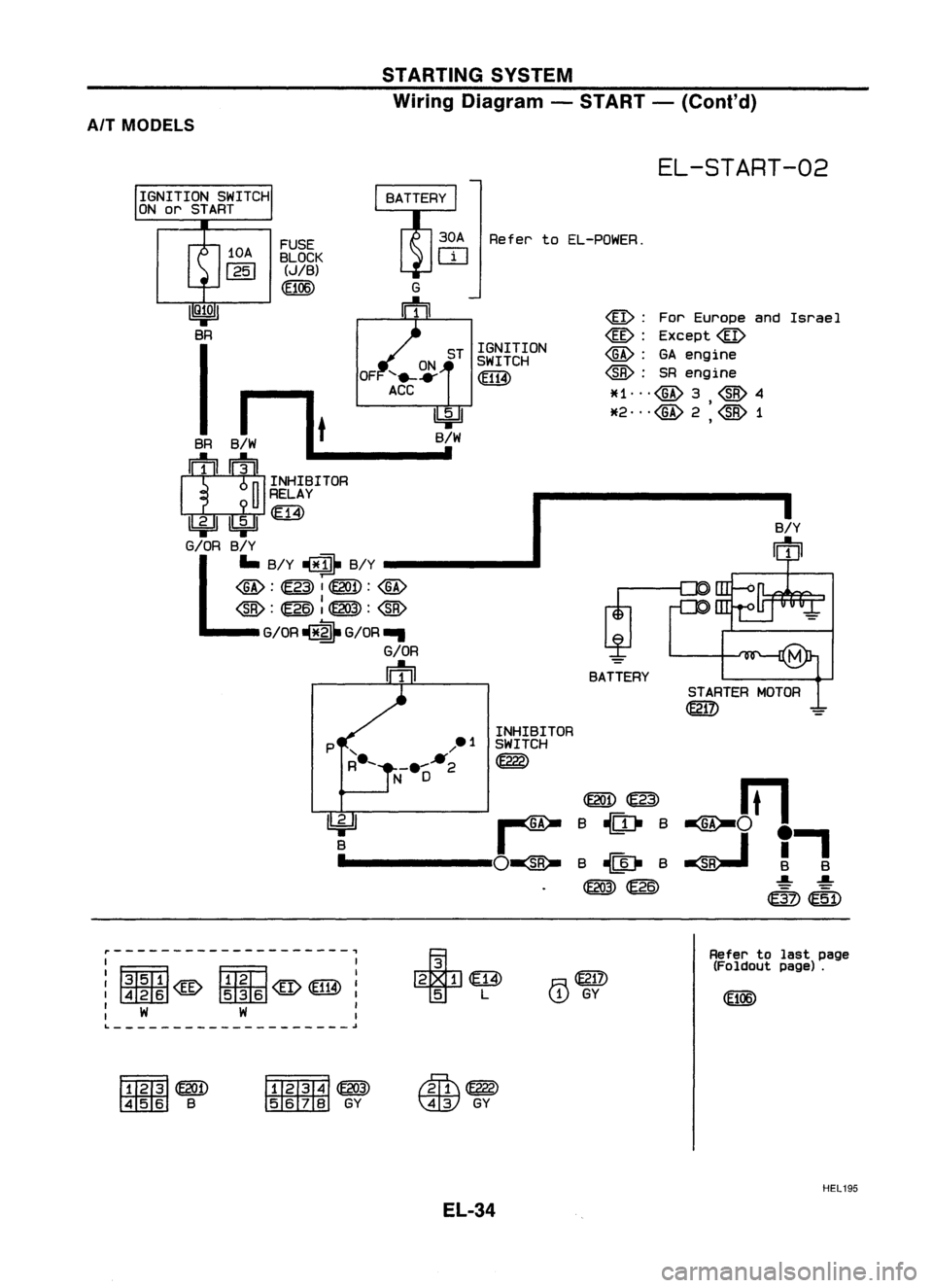
STARTINGSYSTEM
Wiring Diagram -START -(Conl'd)
AIT MODELS
EL-START-02
STARTER MOTOR
~
I
B/Y
m
@:
ForEurope andIsrael
@:
Except@
@:
SRengine
~H"'@3 @4
*2 ...
@
1
,
BATTERY
~~
B ~ B
B ~ B
~~
INHIBITOR
SWITCH
@g)
Refer
toEL-POWER.
ST IGNITION
SWITCH
*
I
FUSE
BLOCK
(JIB)
~B
•
IQ~OI
BR
I
OF
SA
J-.
-It
I
1111 --
n
INHIBITOR
u
RELAY
lkjJIlbjdlffi)
G/OR B/Y
lJ
B/Y~B/Y
@:~IOO:@
G/OR ~ G/OR...
G/OR
Iftn
r--------------------,
I I
I~
FmTl
I
: @@lID
@
tIDrnI
@
@W :
: W W :
L
~
~
T
L
R~
'.!J
GY
Refer
tolast page
(Foldout page).
~~
~B ~~
~GY
Iffi\m>
\AW
GY
HEL195
EL-34
Page 407 of 1701

STARTINGSYSTEM
Trouble Diagnoses
If any abnormality isfound, immediately disconnectbatterynegative terminal.
Starter doesnotstop.
Engine doesnotstart. Replace
magnetic switch.
Does engine turnbycranking? Doesengine turnnormally? Check
ignition/fuel system.
No No
(Turns slowly.)
Check battery asfollows:
OK
Repairstarter motor.
• Charging condition
• Terminal connections
• Terminal corrosion
NG
@
Does starter motorturn? Yes
Doesgearshaft turn? Checkpinionclutch.
No No
Check reduction gear,armature
and gear shaft.
Check fuseandfusible link. Replace.
OK
Check battery asfollows:
@
• Charging condition
• Terminal connections
NG
• Terminal corrosion •
Charge battery.
• Repair connections andcorro-
OK
sian
ofbattery terminals.
Check starting systemwiring.
Repair.
OK
Does magnetic switchoperation No
Replace magnetic switch
sound occur?
Yes
Check condition ofpinion and
OK
Doesstarter turnunder noload Yes
Replace magnetic switch.
ring gear mesh.
byconnecting wiresasfollows?
NG
•
• Adjust pinionmovement.
Repairstarter motor.
• Check pinionmoving mecha-
nism .
• Check ringgear.
SELOO9Z
EL-35
Page 408 of 1701
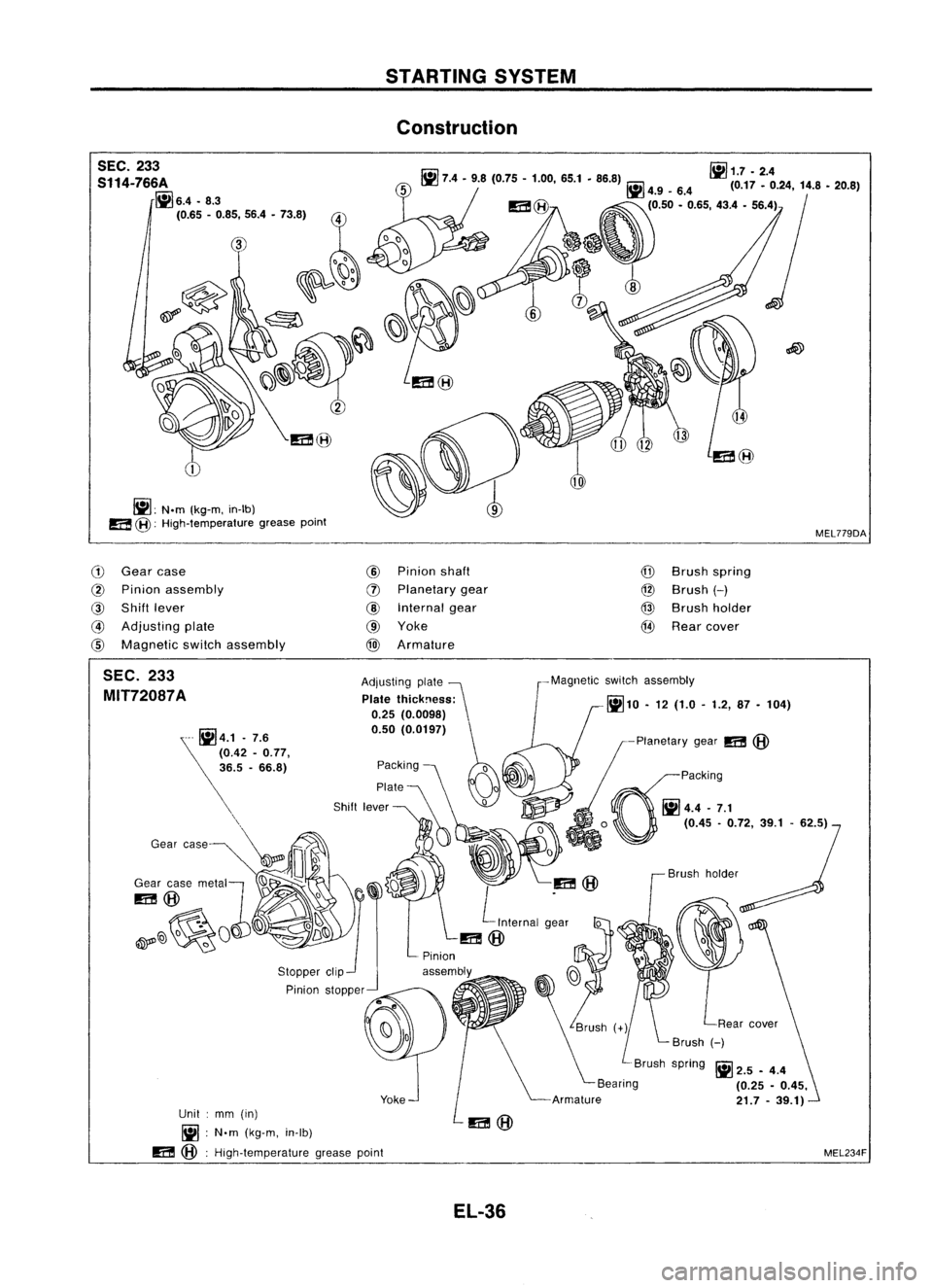
STARTINGSYSTEM
Construction
SEC. 233
S114-766A
~6.4.8.3
(0.65 -0.85, 56.4•73.8)
~: N.m(kg-m, in-Ib)
a
@:
High-temperature greasepoint
r.ii1
iii
1.7 •2.4
III 7.4-9.8 (0.75 -1.00, 65.1•86.8) ~4.9_6.4 (0.17_0.24, 14.8•20.8)
(0.50 -0.65, 43.4•56.4)
MEL779DA
G)
Gear case
@
Pinion assembly
@
Shift lever
@
Adjusting plate
@
Magnetic switchassembly
@
Pinion shaft
(J)
Planetary gear
@
Internal gear
@ Yoke
@
Armature
@
Brush spring
@
Brush
H
@
Brush holder
@
Rear cover
MEL234F
Ii!
2.5 -4.4
(0.25 -0.45,
21.7 -39.1)
Brush
holder
-Planetary
gear
m
@
~paCking
~4.4-7.1
o
(0.45-0.72, 39.1-62.5)
-Magnetic
switchassembly
~10 •12 (1.0 -1.2, 87-104)
Adjusting
plate~
Plate thickness:
0.25 (0.0098)
0.50 (0.0197)
Packing
0
Plate KJo
~
~m@
L
Internal g~ar
0
m@
Yoke
Pinion
stopper
Unit :mm (in)
Ii! :
N'm (kg-m, in-Ib)
m
@:
High-temperature greasepoint
SEC.
233
MIT72087A
EL-36
Page 409 of 1701
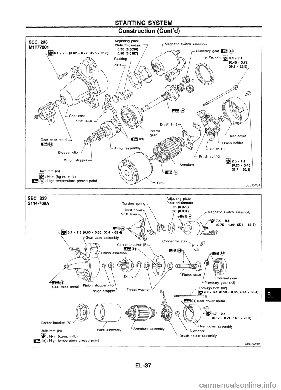
STARTINGSYSTEM
Construction (Cont'd)
SEC. 233
M1T77281
\:; ,o42•
0:
365•66.'}
Gear casemetal
m@
Unit: mm(in)
~: N.m
(kg-m, in-Ib)
m
@:
lligh-temperature greasepoint [Magnetic
SWitrChas:~::~ry gear
m@
~paCking ~4.4-7.1
(0.45 -0.72,
~ 39.1•62.5)
~
/'
~;:/ ~o
C)~G
Brushholder
Brush spring
~2.5-
4.4
(0.25 .0.45,
21.7 .39.1)
SEL151SA
SEC. 233
Adjustingplate
S114-769A
T::~~nc::~~g~p,a~~£~~~~~fr:Magneticswitchassembly
Shift lever ),~
m@
02,
Gear caseassembly
0
Connector stay
p
': Centerbr
o ~
I!E!
l~ \
I!E!@I\.' ~I!E!
(flJ
0" ;P
p;o;o~,,~ ~~~
7~0
I]
(J ,(
"';0'.5'..
P,",oo,.,. ~"""
Qo \
Planetarygear(x3)
Pinion stopper clip /_Through bolt(x2) •
1i'iI14.9 •6.4 (0.50 •0.65, 43.4.56.4)
Pinion
stopper _~
Ollll!
3J
~ cp
~m\@R"i'7m,::
~ l]J ~.
'0.17.0.24,14.'. 20.'}
Center bracket (A)
~oo
Rearcover assembly
Yoke assembly Armatureassembly S-washer
Unit: mm(in) Brushholder assembly
~: N.m
(kg-m, in-Ib) .
m
@:
High-temperature greasePOint SEL902RA
EL-37
Page 410 of 1701
![NISSAN ALMERA N15 1995 Service Manual STARTINGSYSTEM
Construction (Cont'd)
SEC. 233
S114.568A
S114-630
Unit: mm(in)
fj] :
N.m (kg-m, in-Ib)
m@ :
High-temperature greasepointDust
cover (Adjusting plate)
Plate
thickness:
0.5 (0.02 NISSAN ALMERA N15 1995 Service Manual STARTINGSYSTEM
Construction (Cont'd)
SEC. 233
S114.568A
S114-630
Unit: mm(in)
fj] :
N.m (kg-m, in-Ib)
m@ :
High-temperature greasepointDust
cover (Adjusting plate)
Plate
thickness:
0.5 (0.02](/img/5/57349/w960_57349-409.png)
STARTINGSYSTEM
Construction (Cont'd)
SEC. 233
S114.568A
S114-630
Unit: mm(in)
fj] :
N.m (kg-m, in-Ib)
m@ :
High-temperature greasepointDust
cover (Adjusting plate)
Plate
thickness:
0.5 (0.020)
0.8 (0.031)
Field coil
•
7.4.9.8 (0.75•1.00. 65.1.86.8)
• 4.9.6.4
(0.50 •0.65. 43.4•56.4)
E-ring
SEL249SC
SEC. 233
M3T37783
Gearcase
Gear casemetal
m
@
Adjusting
plate
Plate
thickness:
0.25 (0.0098)
0.50 (0.0197)
Armature
Unit: mm(in)
fj]:
N.m(kg-m. in-Ib)
m
@:
High-temperature greasepoint
EL-38
IiJ
2.5-4.4
r.ilI
(0.25-0.45.
~ 4.4•7.1 21.7•39.1)
(0.45 •0.72.
~
SEL464PA