NISSAN ALMERA N15 1995 Service Manual
Manufacturer: NISSAN, Model Year: 1995, Model line: ALMERA N15, Model: NISSAN ALMERA N15 1995Pages: 1701, PDF Size: 82.27 MB
Page 851 of 1701
TROUBLEDIAGNOSIS FORNON-DETECTABLE ITEMS
Throttle Position Sensor(Cont'd)
~io
~ SEF461Q
II
~i8
ECM
E
CONNECTOR
II
20 23
@:
ForAustralia
@:
Except forAustralia
SEF229R
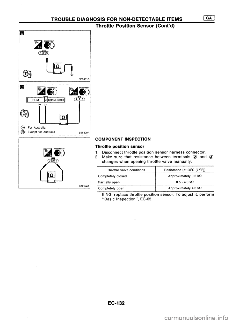
COMPONENT INSPECTION
Throttle position sensor
1. Disconnect throttleposition sensorharness connector.
2. Make surethatresistance betweenterminals
@
and
@
changes whenopening throttlevalvemanually.
SEF146R
Throttle
valveconditions
Completely closed
Partially open
Completely open Resistance
(at25'C (77'F)J
Approximately 0.5
kn
0.5 -4.0
kn
Approximately 4.0
kn
If NG, replace throttleposition sensor.Toadjust it,perform
"Basic Inspection", EC-65.
EC-132
Page 852 of 1701
TROUBLEDIAGNOSIS FORNON-DETECTABLE ITEMS
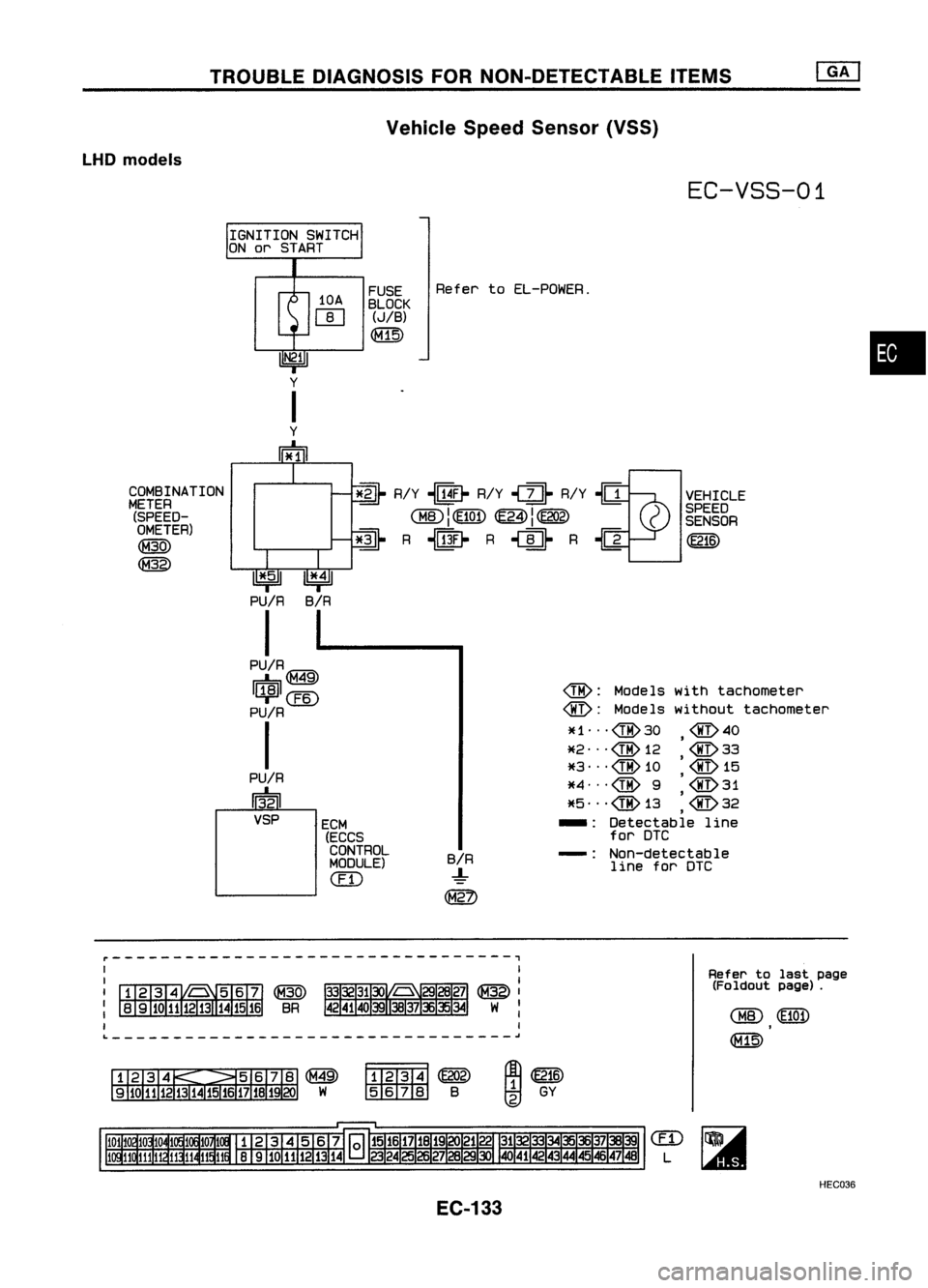
Vehicle SpeedSensor (VSS)
LHD
models
EC-VSS-01
FUSE RefertoEL-POWER.
BLOCK
(JIB)
~
•
~ R/Y
-illfr
R/Y~~ R/Y-Ia~ VEHICLE
rITO)l~ ~I~ )
SPEED
0:@..;
I~ ~I~
(SENSOR
~ R
-lliW~
R~~ R~
@ID
COMBINATION
METER (SPEED-
OMETER)
~
~
1*.51
PU/R
I
PU
IR
IG"An\
d:::,~
I~ICEID
PU/R
I
PU/R
~VSP ECM
(ECCS
CONTROL
MODULE)
ill)
B/R
-!-
~
@:
Models withtachometer
@:
Modelswithout tachometer
*1 ... @30 @40
,
*2"'@12 @33
*3 ... @10 '@15
*4"'@ 9'@31
,
*5 ... @ 13 @32
,
-: Detectable line
for DTC
-: Non-detectable
line forDTC
L ~
~~
tIDID11ID
B
Refer
tolast page
(Foldout page).
~@ID
tID
GY
EC-133
em
L
HEC036
Page 853 of 1701
TROUBLEDIAGNOSIS FORNON-DETECTABLE ITEMS
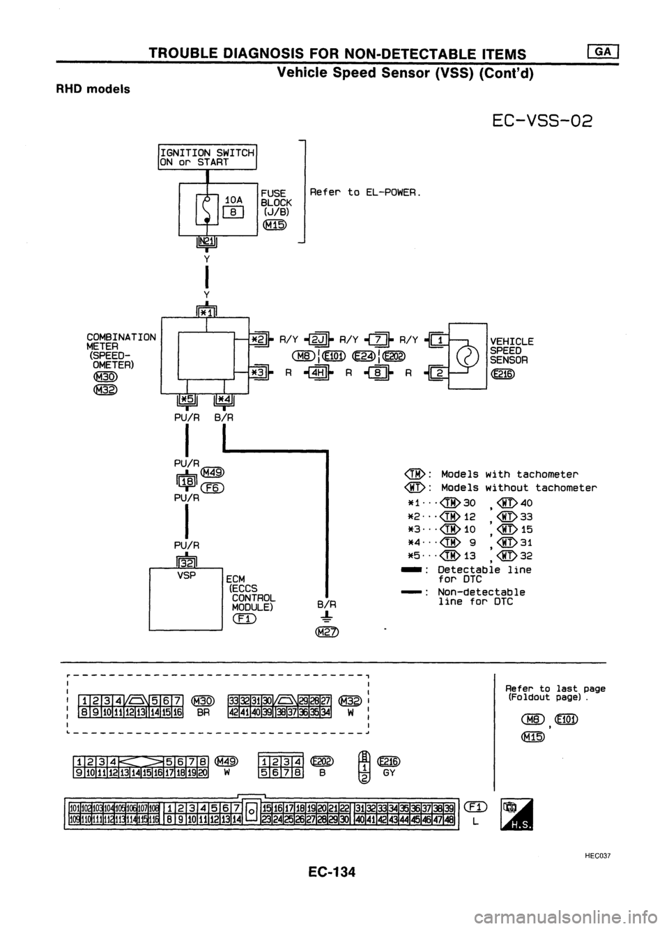
Vehicle SpeedSensor (VSS)(Cont'd)
RHO models
EC-VSS-02
IGNITION SWITCH
ON orSTART
~R/Y
.j~
R/Y
.j~
R/Y~..gVEHICLE
rTIO\llE7iIT\
1E"n\1~ )SPEED
~ I
'l:1Q.y ~
I~
(SENSOR
~ R
.j1IDJ-
R
.j~
R~ ~
10A
[]]
Refer
toEL-POWER.
@:
Models withtachometer
@:
Models without tachometer
*1 @30 @40
*2
@
12 '@33
*3
@
10
'@
15
*4
@
9'@31
,
*5 ... @13 @32
,
-: Detectable line
for DTC
-: Non-detectable
line foraTC
B/R
-!-
FUSE
BLOCK
(JIB)
~
ECM (ECCS
CONTROL
MODULE)
em
1*151
PUIR
I
PU/RtG7?l\ r=b~
I~I@
PU/R
I
PU/R
13
1
21
VSP
COMBINATION
METER (SPEED-
OMETER)
~
~
L ~
~~
tmm:lID
B
~WID
tgj
GY
Refer
tolast page
(Foldout page).
em
L
HEC037
EC-134
Page 854 of 1701
TROUBLEDIAGNOSIS FORNON-DETECTABLE ITEMS
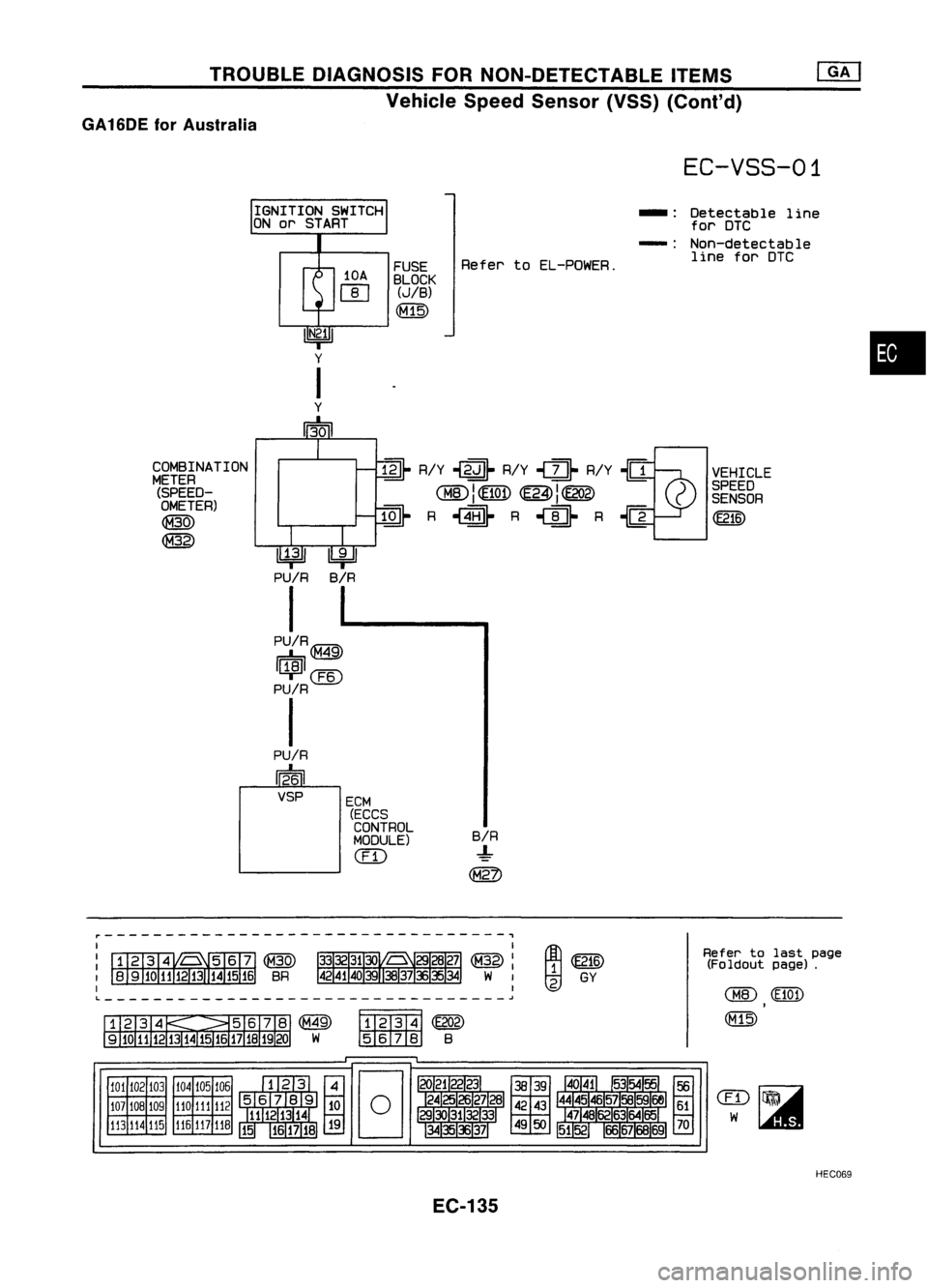
Vehicle SpeedSensor (VSS)(Conl'd)
GA 16DE forAustralia
EC-VSS-01
~ R/Y~~ R/Y,
U-
R/Y~{1VEHICLE
~I~ ~I~ )
SPEED
~ I
'l::.!Q!, ~
J~
C
SENSOR
~ R,~ R
'U-
R{] ~
IGNITION
SWITCH
ON or START
10A
[]]
•
Detectable
line
for DTC
Non-detectable line forDTC
-:
-:
B/R
-!-
~
Refer
toEL-PDWER.
FUSE
BLOCK
(JIB)
(M15)
ECM (ECCS
CONTROL
MODULE)
(ill
~
PU/R
I
PU/RIGM'l\
r=b,~
I~I@
PU/R
I
PU/R
1~61
VSP
COMBINATION
METER (SPEED-OMETER)
~
@
Refertolast page
(Foldout page).
~~
~ GY
@
Fff2T3T4j
(E202)
w
IID:illIID
B
104 105106
110 111
112
116 117
11B
101
102 103
107 10B 109
113 114
115
~---------------------------------,
L ~
HEC069
EC-135
Page 855 of 1701
TROUBLEDIAGNOSIS FORNON-DETECTABLE ITEMS
@!J
Vehicle SpeedSensor (VSS)(Conl'd)
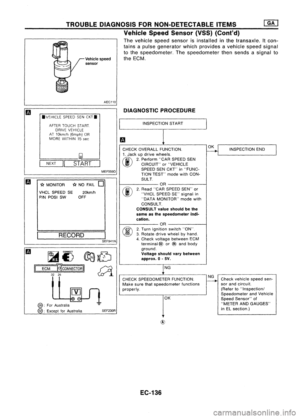
The vehicle speedsensor isinstalled inthe transaxle. Itcon-
tains apulse generator whichprovides avehicle speedsignal
to the speedometer. Thespeedometer thensends asignal to
Vehicle speed theECM.
sensor
AEC110 DIAGNOSTIC PROCEDURE
.V~HICLE SPEEDSENCKT.
AFTER TOUCH START.
DRIVE VEHICLE
AT 10km/h (6mph)OR
MORE WITHIN 15
see
INSPECTION
START
SEF941N
-(;(
NO FAIL
0
fijf.....
CONNECT
fIr:J:J:.~
1A1£) ~~
ECM
19'
CONNECTOR
II~
32 26
~l
INSPECTION
END
Check vehicle speedsen-
sor and circuil.
(Refer to"Inspectionl
Speedometer andVehicle
Speed Sensor" of
"METER ANDGAUGES"
in EL section.)
OK
NG
OK
NG
CHECK SPEEDOMETER FUNCTION.
Make surethatspeedometer functions
properly.
CHECK
OVERALL FUNCTION.
1. Jack updrive wheels.
(ij\
2.Perform "CARSPEED SEN
~ CIRCUIT" or"VEHICLE
SPEED SENCKT'" in"FUNC-
TION TEST'" modewithCON-
SULT OR
2. Read "CAR SPEED SEN"'or
"VHCL SPEED SE"signal in
"DATA MONITOR" modewith
CONSULT.
CONSULT valueshould bethe
same asthe speedometer indi-
cation. OR
2. Turn ignition switch"ON".
3. Rotate drivewhe'el byhand.
4. Check voltage between ECM
terminal
@
or@ and body
ground.
Voltage shouldvarybetween
approx. 0-5V.
SEF230R
MEF559D
20km/h
OFF
RECORD
l----
__ ,~--'
-N-EX-T
-II
STA-RT-
-(;( MONITOR
VHCL SPEED SE
PIN POSI SW
@:
ForAustralia
@:
Except forAustralia
II
EC-136
Page 856 of 1701
TROUBLEDIAGNOSIS FORNON-DETECTABLE ITEMS
Vehicle SpeedSensor (VSS)(Cont'd)
m
Models withtachometer
II
ECM
@ :For Australia
@ :Except forAustralia
Models without tachometer
II
ECM
@
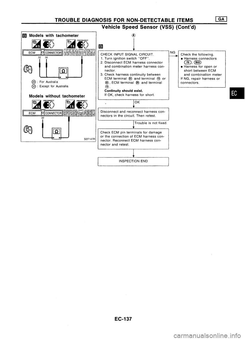
CHECK INPUTSIGNAL CIRCUIT.
1. Turn ignition switch"OFF".
2. Disconnect ECMharness connector
and combination meterharness con-
nector.
3. Check harness continuity between
ECM terminal
@
and terminal
@
or
@,
ECM terminal
@
and terminal
@.
Continuity shouldexist.
If OK, check harness forshort.
OK
Disconnect andreconnect harnesscon-
nectors inthe circuit. Thenretest.
Trouble isnot fixed.
NG
Check thefollowing.
• Harness connectors
GD,@
• Harness foropen or
short between ECM
and combination meter
If
NG, repair harness or
connectors.
•
SEF147R
Check
ECMpinterminals fordamage
or the connection ofECM harness con-
nector. Reconnect ECMharness con-
nector andretest.
INSPECTION END
EC-137
Page 857 of 1701
TROUBLEDIAGNOSIS FORNON-DETECTABLE ITEMS
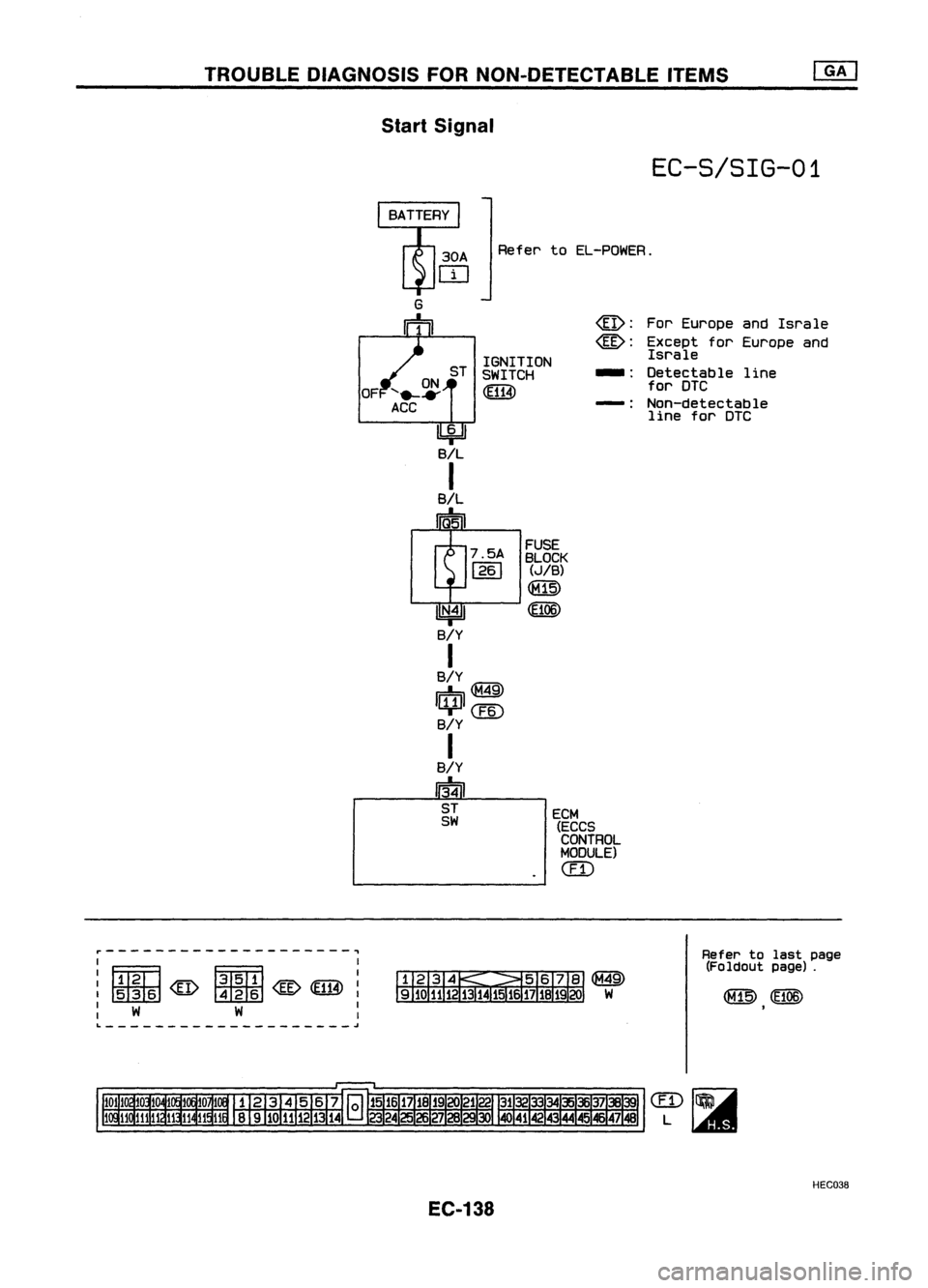
Start Signal
EC-S/SIG-01
Refer toEL-POWER.
ECM
(ECCS
CONTROL
MODULE)
(IT)
For
Europe andIsrale
Except forEurope and
Israle
Detectable line
for DTC
Non-detectable line forDTC
_.
-:
@:
@:
FUSE
BLOCK
(JIB)
~
0:106)
7.5A
1261
ST
IGNITION
SWITCH
~
U
N•4
11
B/Y
I
B/Y
r::b@
I[QJI
CEID
B/Y
I
B/Y
~ ST
SW
OF
r--------------------,
I I
IFmfl ~ I
: rmm
: W W :
L
~
Refer
tolast page
(Foldout page).
HEC038
EC-138
Page 858 of 1701
TROUBLEDIAGNOSIS FORNON-DETECTABLE ITEMS
Start Signal (Cont'd)
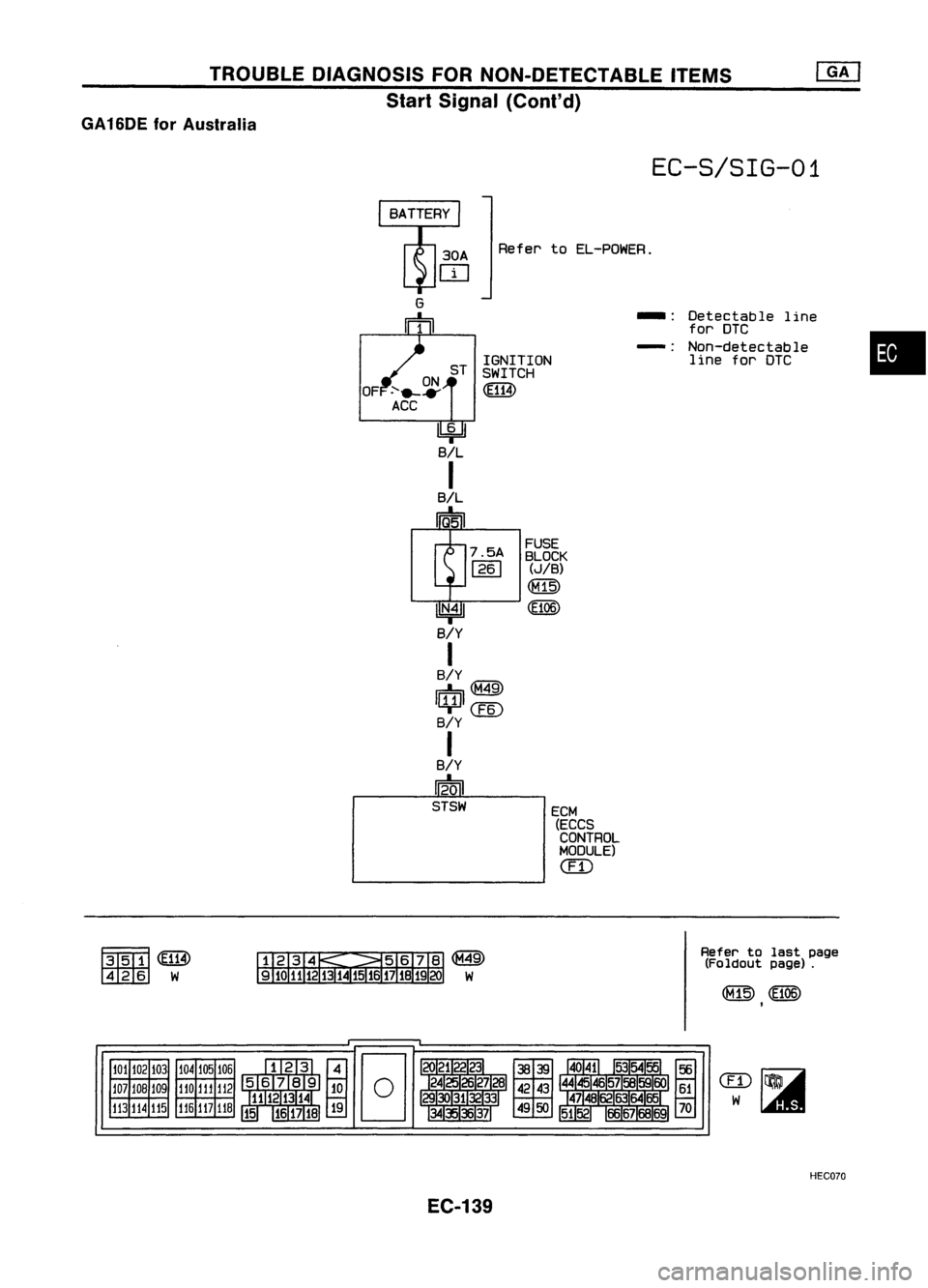
GA16DE forAustralia
EC-S/SIG-01
Refer toEL-POWER.
•
-:
Detectable line
for DTC
-: Non-detectable
line forDTC
ECM (ECCS
CONTROL
MODULE)
ern
FUSE
BLOCK
(JIB)
CE106)
7.5A
1261
ST
IGNITION
SWITCH
~
30A
OJ
IN.41
SlY
I
BIY
r.::b@
l/¥ll@)
SlY
I
SlY
~
STSW
~~
tmI
W
Refer
tolast page
(Foldout paglil).
101 102 103
107 108 109
113 114
115 104
105106
110
111
112
116
117
118
HEC070
EC-139
Page 859 of 1701
TROUBLEDIAGNOSIS FORNON-DETECTABLE ITEMS
Start Signal (Cont'd)
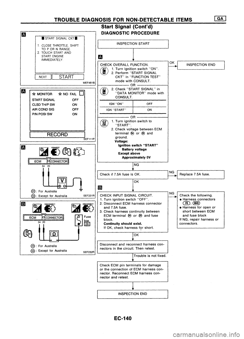
DIAGNOSTIC PROCEDURE
CHECK OVERALL FUNCTION.
00
1.
Turn ignition switch"ON".
I
II
2.
Perform "STARTSIGNAL
NEXT
START
CKT"
in"FUNCTION TEST"
MEF481B mode
withCONSULT.
OR
m
00
2.
Check "START SIGNAL" in
* MONITOR *
NO FAIL
0
"DATA
MONITOR" modewith
START SIGNAL CONSULT.
OFF
I
CLSDTH/PSW
ONIGN
"ON" OFF
AIR COND SIG OFF
IGN"START" ON
PIN POSI SW ON
II
•
START SIGNAL CKT.
CLOSE THROTTLE. SHIFT
TO POR NRANGE.
2. TOUCH STARTAND
START ENGINE
IMMEDIATELY.
~ __ RE_C_O_R_D_---,l
SEF111P
~I)~ID
ECM
B
CONNECTOR
II
34 20
INSPECTION
START
OR
1. Turn ignition switchto
"START".
2. Check voltage between ECM
terminal @or
@l
and
ground.
Voltage:
Ignition switch"START"
Battery voltage
Except above
Approximately OV
NG OK
INSPECTION END
II
@:
ForAustralia
34 :Except forAustralia
~Io
ECM
ET
CONNECTOR
II
34 20
@:
ForAustralia
@:
Except forAustralia SEF231R
SEF232R Check
if7.5A fuseisOK.
OK
CHECK INPUTSIGNAL CIRCUIT.
1. Turn ignition switch"OFF".
2. Disconnect ECMharness connector
and 7.5A fuse.
3. Check harness continuity between
ECM terminal @or
@l
and fuse
block.
Continuity shouldexist.
If OK, check harness f<;>rshort.
OK
Disconnect andreconnect harnesscon-
nectors inthe circuit. Thenretest.
Trouble isnot fixed.
Check ECMpinterminals fordamage
or the connection ofECM harness con-
nector. Reconnect ECMharness con-
nector andretest.
INSPECTION END
EC-140
NG
NG
Replace
7.5Afuse.
Check thefollowing.
• Harness connectors
(ID,@
• Harness foropen or
short between ECM
and fuse block
If NG, repair harness or
connectors.
Page 860 of 1701
TROUBLEDIAGNOSIS FORNON-DETECTABLE ITEMS
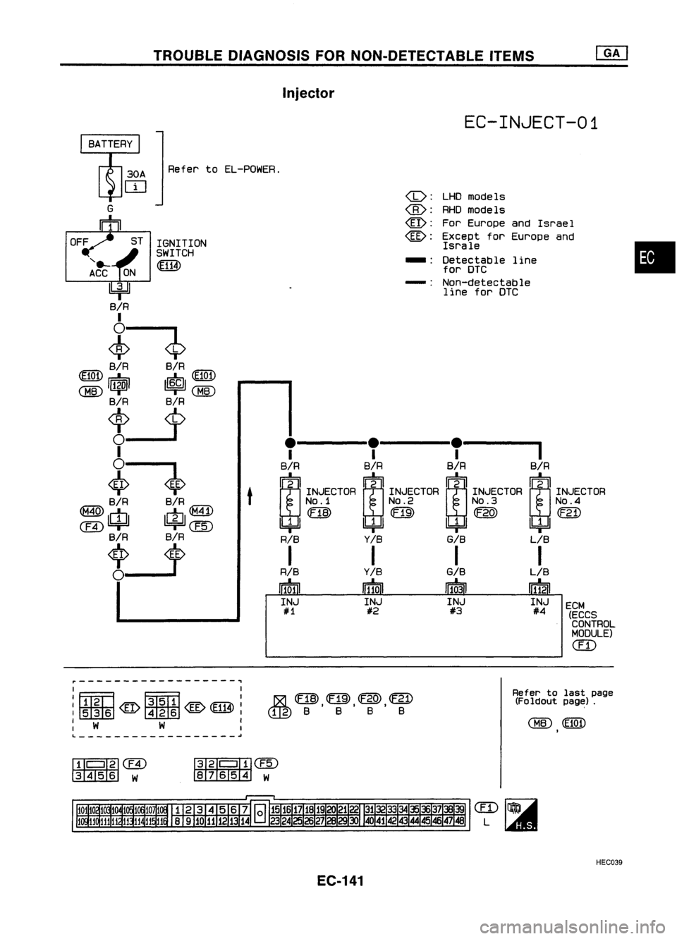
Injector
EC-INJECT-01
Refer toEL-POWER.
G
rh
•
ECM (ECCSCONTROL
MODULE)
ill)
LHO
models
RHO models
For Europe andIsrael
Except forEurope and
Israle
Detectable line
for DTC
Non-detectable line forDTC
-: -:
(b):
@:
@:
@:
.-----'.-----.-----
I I I
SIR BIRBIR BIR
rn
2 ~2rn
fi1=i1
rn2
INJECTOR
INJECTORINJECTOR INJECTOR
NO.1 NO.2NO.3 NO.4
(EJ]) rn~
(F21)
4=B 4=B
4JJ
4=B
RIS Y/B
GIB
LIB
I I II
RIB Y/B
G/B
LIB
rmru In10iJ
11~31 11~21
INJ INJINJ INJ
#1 #2#3 #4
t
ST
IGNITION
SWITCH
~
'e-
ACC
4J
SIR
I
~$
SIR SIR
m
r=b
t=
(EiOt)
<:BID
I~I ~
<:BID
SIR SiR
1;>-1>
I
~.
SIR SIR
IG7'A\
~m rn~
ernl4=Jl
l!::i=Jl@
SIR SIR
U
OFF
~------------------~
, ,
'FITm ~
I
:rnrnID@~@@:
: W W :
L ~
1&1
(EJ]),rn,@,~
@B BBB
Refer
tolast page
(Foldout page;J.
<:BID ~
I
rn'
I
'fil
ern
3456
W
~I
,1f.I)@
87654 W
HEC039
EC-141