NISSAN ALMERA N16 2003 Electronic Repair Manual
Manufacturer: NISSAN, Model Year: 2003, Model line: ALMERA N16, Model: NISSAN ALMERA N16 2003Pages: 3189, PDF Size: 54.76 MB
Page 2711 of 3189
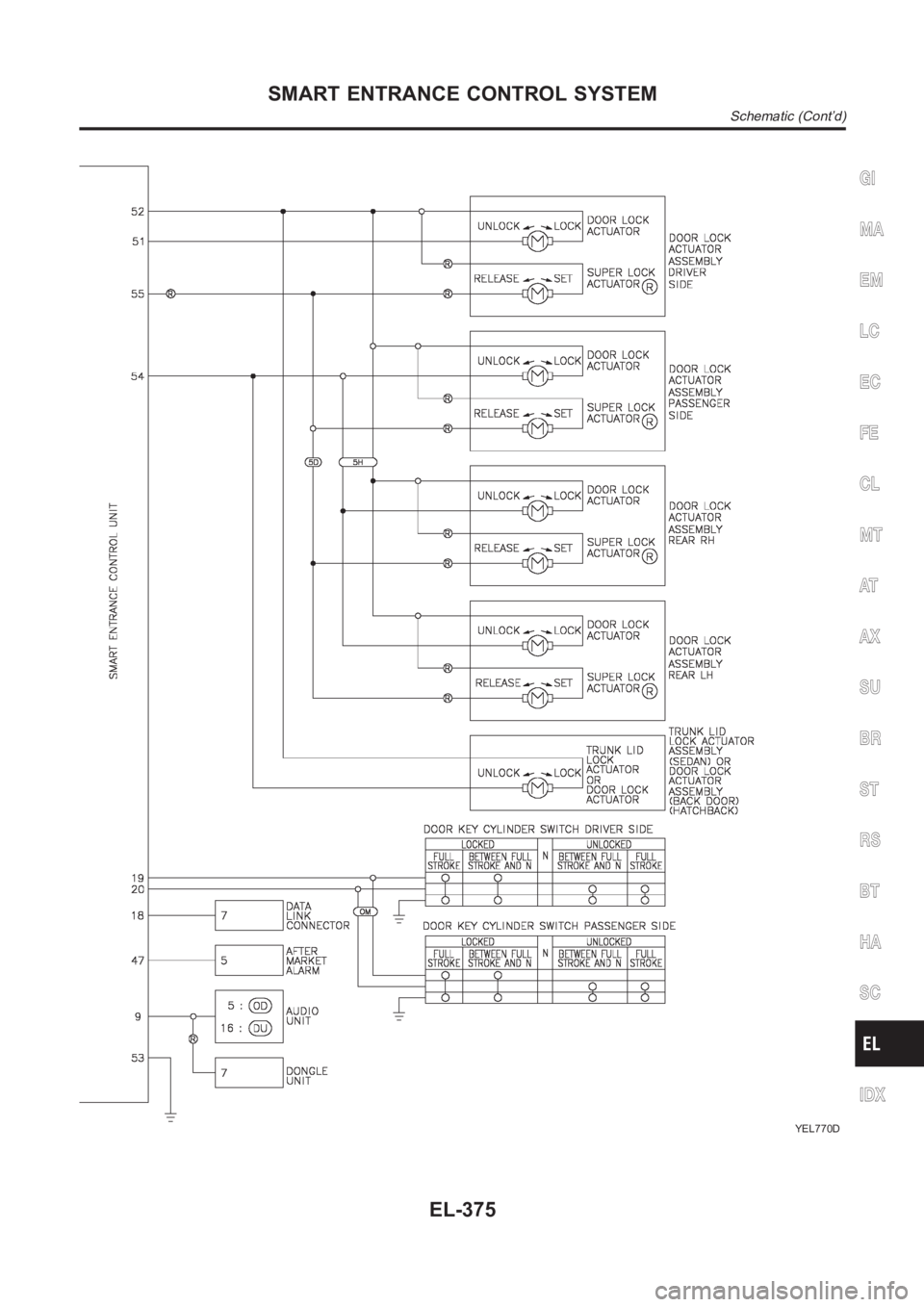
YEL770D
GI
MA
EM
LC
EC
FE
CL
MT
AT
AX
SU
BR
ST
RS
BT
HA
SC
IDX
SMART ENTRANCE CONTROL SYSTEM
Schematic (Cont’d)
EL-375
Page 2712 of 3189
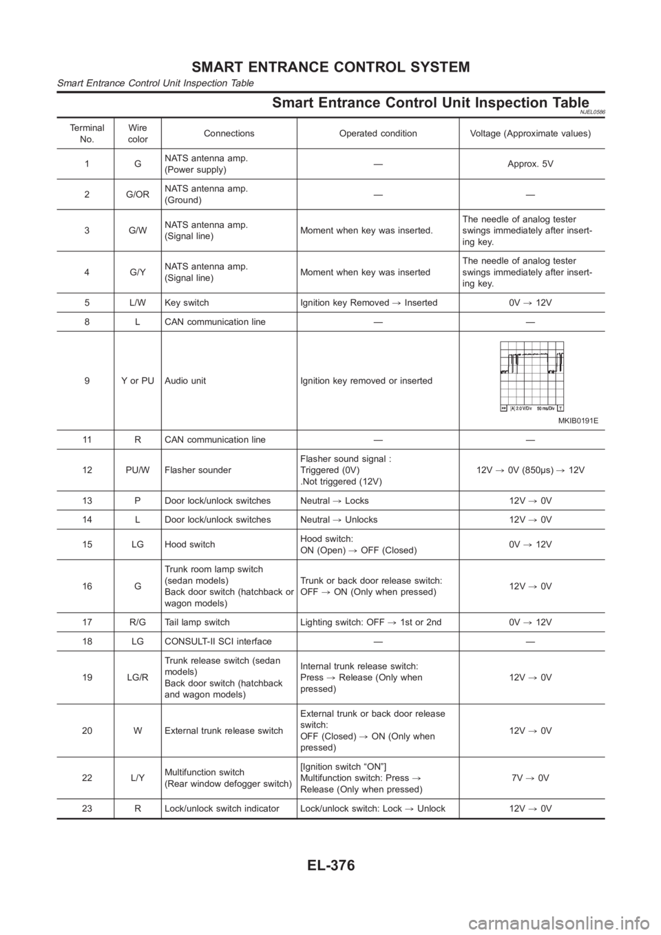
Smart Entrance Control Unit Inspection TableNJEL0586
Terminal
No.Wire
colorConnections Operated condition Voltage (Approximate values)
1GNATS antenna amp.
(Power supply)— Approx. 5V
2 G/ORNATS antenna amp.
(Ground)——
3 G/WNATS antenna amp.
(Signal line)Moment when key was inserted.The needle of analog tester
swings immediately after insert-
ing key.
4 G/YNATS antenna amp.
(Signal line)Moment when key was insertedThe needle of analog tester
swings immediately after insert-
ing key.
5 L/W Key switch Ignition key Removed,Inserted 0V,12V
8 L CAN communication line — —
9 Y or PU Audio unit Ignition key removed or inserted
MKIB0191E
11 R CAN communication line — —
12 PU/W Flasher sounderFlasher sound signal :
Triggered (0V)
.Not triggered (12V)12V,0V (850μs),12V
13 P Door lock/unlock switches Neutral,Locks 12V,0V
14 L Door lock/unlock switches Neutral,Unlocks 12V,0V
15 LG Hood switchHood switch:
ON (Open),OFF (Closed)0V,12V
16 GTrunk room lamp switch
(sedan models)
Back door switch (hatchback or
wagon models)Trunk or back door release switch:
OFF,ON (Only when pressed)12V,0V
17 R/G Tail lamp switch Lighting switch: OFF,1st or 2nd 0V,12V
18 LG CONSULT-II SCI interface — —
19 LG/RTrunk release switch (sedan
models)
Back door switch (hatchback
and wagon models)Internal trunk release switch:
Press,Release (Only when
pressed)12V,0V
20 W External trunk release switchExternal trunk or back door release
switch:
OFF (Closed),ON (Only when
pressed)12V,0V
22 L/YMultifunction switch
(Rear window defogger switch)[Ignition switch “ON”]
Multifunction switch: Press,
Release (Only when pressed)7V,0V
23 R Lock/unlock switch indicator Lock/unlock switch: Lock,Unlock 12V,0V
SMART ENTRANCE CONTROL SYSTEM
Smart Entrance Control Unit Inspection Table
EL-376
Page 2713 of 3189
![NISSAN ALMERA N16 2003 Electronic Repair Manual Terminal
No.Wire
colorConnections Operated condition Voltage (Approximate values)
24 BRWasher switch
(Headlamp washer switch)[Head lamp switch 1st or 2nd posi-
tion]
Washer switch OFF,ON12V,0V
25 G/OR NISSAN ALMERA N16 2003 Electronic Repair Manual Terminal
No.Wire
colorConnections Operated condition Voltage (Approximate values)
24 BRWasher switch
(Headlamp washer switch)[Head lamp switch 1st or 2nd posi-
tion]
Washer switch OFF,ON12V,0V
25 G/OR](/img/5/57350/w960_57350-2712.png)
Terminal
No.Wire
colorConnections Operated condition Voltage (Approximate values)
24 BRWasher switch
(Headlamp washer switch)[Head lamp switch 1st or 2nd posi-
tion]
Washer switch OFF,ON12V,0V
25 G/ORCombination switch
(Turn signal switch)Turn signal switch:
Neutral,Left turn position12V,0V
26 L/BCombination switch
(Turn signal switch)Turn signal switch:
Neutral,Right turn position12V,0V
27 Y/BVehicle security horn relay
(RHD models)When theft warning system:
Armed,Disarmed0V,12V
28 R/Y Interior room lampWhen interior lamp is operated using
remote controller (Lamp switch in
“DOOR” position)12V,0V
29 Y/G Ignition key switch Ignition key is in “ON” position 12V
30 G/R Hazard switch Hazard switch: OFF,ON 12V,0V
31 W Rear window defogger relay[Ignition switch “ON”]
Rear window defogger switch:
OFF,ON12V,0V
32 LG/B Cooling fan relay[Ignition switch“ ON”]
Cooling fan: Operating,Not operat-
ing0V,12V
33 LG/R Cooling fan relay[Ignition switch “ON”]
Cooling fan: Operating,Not operat-
ing0V,12V
34 L/Y Security indicator Ignition switch ON,OFF 12V,0V
39 BR/WRear door switch
(Passenger side)Rear door LH or RH: Open,Closed 0V,12V
41 L Air conditioner relay[Engine is running]
Air conditioner switch: ON,
OFF12V,0V
43 R/WFront door switch
(Driver side)Front door (Driver side):
Open,Closed12V,0V
44 R/WFront door switch
(Passenger side)Front door (Passenger side):
Open,Closed0V,12V
45 R/YRear door switch
(Driver side)Rear door LH or RH: Open,Closed 0V,12V
49 W/L Power source — 12V
50 GPower door super lock actuator
(Rear)Remote controller door lock switch:
Free,Press0V,12V
51 L/R Driver door lock actuatorDoor lock & unlock switch:
Free,Lock0V,12V
52 W/R Door lock actuatorsDoor lock & unlock switch:
Free,Unlock0V,12V
53 B Ground — 0V
54 R/B Door lock actuatorsDoor lock & unlock switch:
Free,Unlock0V,12V
55 W/BPower door super lock actuator
(Front)Remote controller door lock switch:
Free,Unlock0V,12V
56 R/B Power source — 12V
GI
MA
EM
LC
EC
FE
CL
MT
AT
AX
SU
BR
ST
RS
BT
HA
SC
IDX
SMART ENTRANCE CONTROL SYSTEM
Smart Entrance Control Unit Inspection Table (Cont’d)
EL-377
Page 2714 of 3189
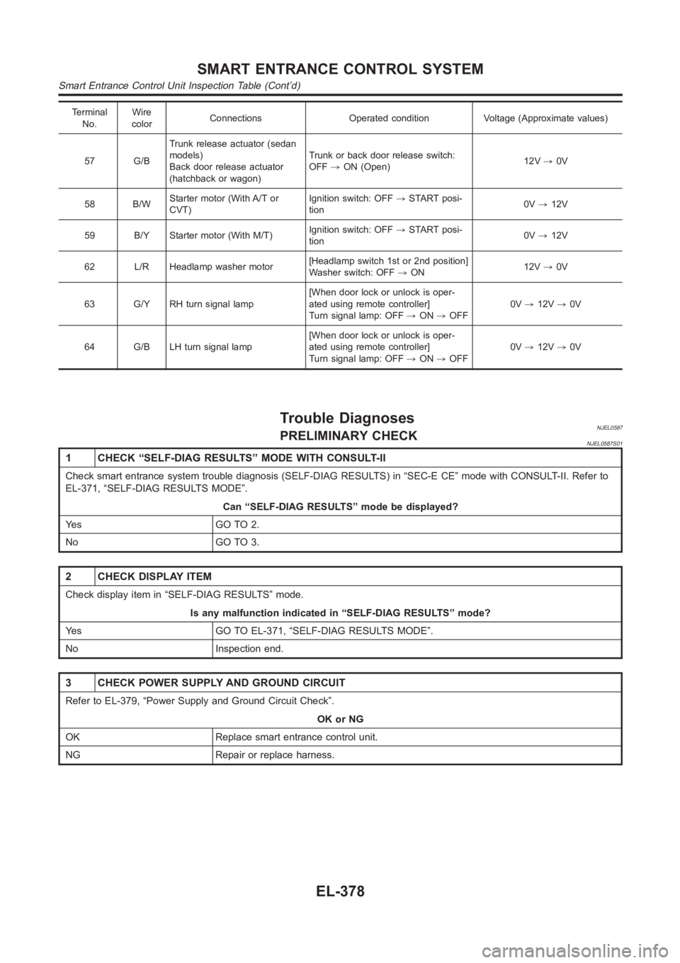
Terminal
No.Wire
colorConnections Operated condition Voltage (Approximate values)
57 G/BTrunk release actuator (sedan
models)
Back door release actuator
(hatchback or wagon)Trunk or back door release switch:
OFF,ON (Open)12V,0V
58 B/WStarter motor (With A/T or
CVT)Ignition switch: OFF,START posi-
tion0V,12V
59 B/Y Starter motor (With M/T)Ignition switch: OFF,START posi-
tion0V,12V
62 L/R Headlamp washer motor[Headlamp switch 1st or 2nd position]
Washer switch: OFF,ON12V,0V
63 G/Y RH turn signal lamp[When door lock or unlock is oper-
ated using remote controller]
Turn signal lamp: OFF,ON,OFF0V,12V,0V
64 G/B LH turn signal lamp[When door lock or unlock is oper-
ated using remote controller]
Turn signal lamp: OFF,ON,OFF0V,12V,0V
Trouble DiagnosesNJEL0587PRELIMINARY CHECKNJEL0587S01
1 CHECK “SELF-DIAG RESULTS” MODE WITH CONSULT-II
Check smart entrance system trouble diagnosis (SELF-DIAG RESULTS) in “SEC-E CE” mode with CONSULT-II. Refer to
EL-371, “SELF-DIAG RESULTS MODE”.
Can “SELF-DIAG RESULTS” mode be displayed?
Ye s G O T O 2 .
No GO TO 3.
2 CHECK DISPLAY ITEM
Check display item in “SELF-DIAG RESULTS” mode.
Is any malfunction indicated in “SELF-DIAG RESULTS” mode?
Yes GO TO EL-371, “SELF-DIAG RESULTS MODE”.
No Inspection end.
3 CHECK POWER SUPPLY AND GROUND CIRCUIT
Refer to EL-379, “Power Supply and Ground Circuit Check”.
OK or NG
OK Replace smart entrance control unit.
NG Repair or replace harness.
SMART ENTRANCE CONTROL SYSTEM
Smart Entrance Control Unit Inspection Table (Cont’d)
EL-378
Page 2715 of 3189
Power Supply and Ground Circuit CheckNJEL0588
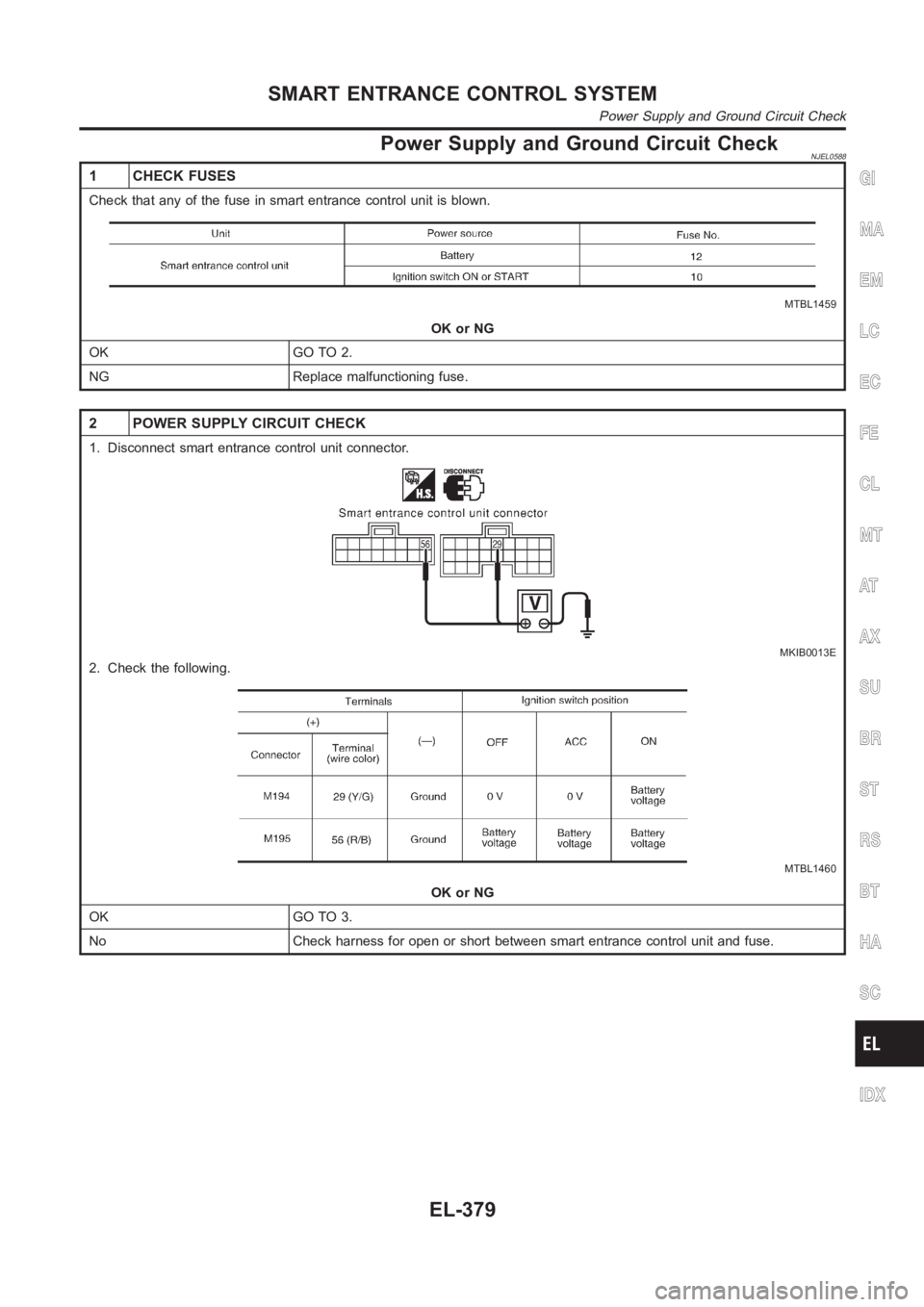
1 CHECK FUSES
Check that any of the fuse in smart entrance control unit is blown.
MTBL1459
OK or NG
OK GO TO 2.
NG Replace malfunctioning fuse.
2 POWER SUPPLY CIRCUIT CHECK
1. Disconnect smart entrance control unit connector.
MKIB0013E
2. Check the following.
MTBL1460
OK or NG
OK GO TO 3.
No Check harness for open or short between smart entrance control unit and fuse.
GI
MA
EM
LC
EC
FE
CL
MT
AT
AX
SU
BR
ST
RS
BT
HA
SC
IDX
SMART ENTRANCE CONTROL SYSTEM
Power Supply and Ground Circuit Check
EL-379
Page 2716 of 3189
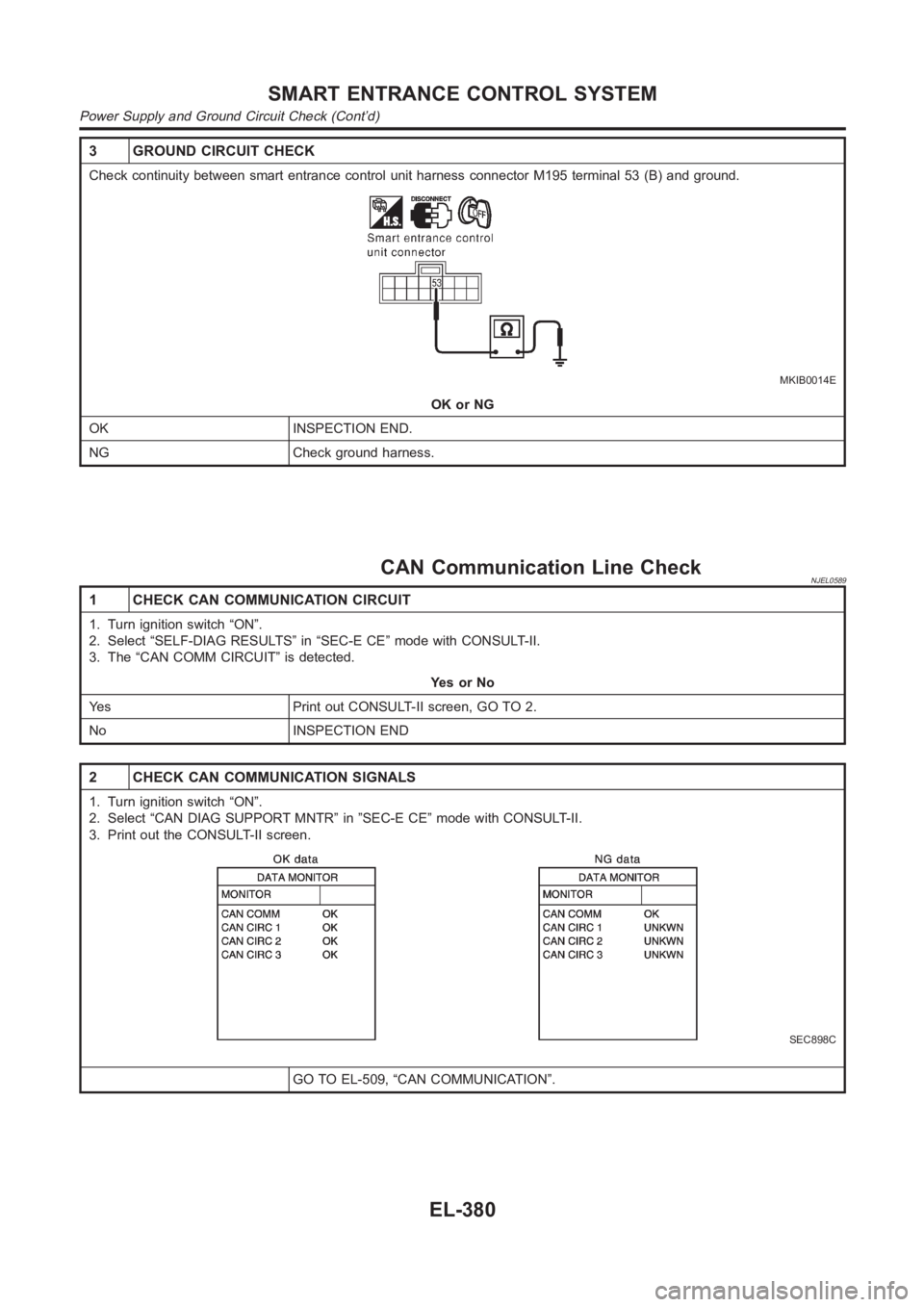
3 GROUND CIRCUIT CHECK
Check continuity between smart entrance control unit harness connector M195 terminal 53 (B) and ground.
MKIB0014E
OK or NG
OK INSPECTION END.
NG Check ground harness.
CAN Communication Line CheckNJEL0589
1 CHECK CAN COMMUNICATION CIRCUIT
1. Turn ignition switch “ON”.
2. Select “SELF-DIAG RESULTS” in “SEC-E CE” mode with CONSULT-II.
3. The “CAN COMM CIRCUIT” is detected.
YesorNo
Yes Print out CONSULT-II screen, GO TO 2.
No INSPECTION END
2 CHECK CAN COMMUNICATION SIGNALS
1. Turn ignition switch “ON”.
2. Select “CAN DIAG SUPPORT MNTR” in ”SEC-E CE” mode with CONSULT-II.
3. Print out the CONSULT-II screen.
SEC898C
GO TO EL-509, “CAN COMMUNICATION”.
SMART ENTRANCE CONTROL SYSTEM
Power Supply and Ground Circuit Check (Cont’d)
EL-380
Page 2717 of 3189
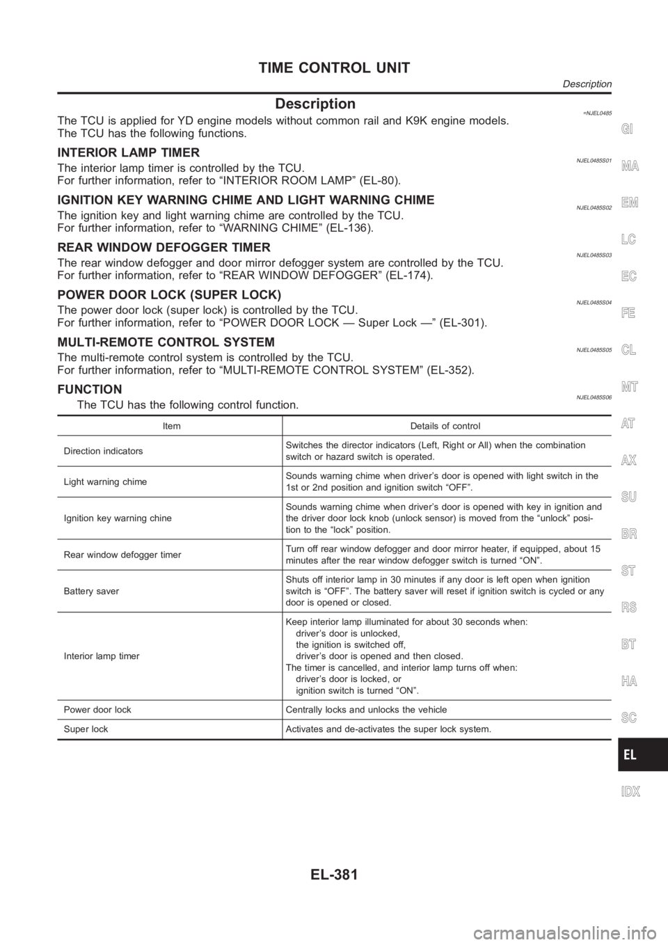
Description=NJEL0485The TCU is applied for YD engine models without common rail and K9K engine models.
The TCU has the following functions.
INTERIOR LAMP TIMERNJEL0485S01The interior lamp timer is controlled by the TCU.
For further information, refer to “INTERIOR ROOM LAMP” (EL-80).
IGNITION KEY WARNING CHIME AND LIGHT WARNING CHIMENJEL0485S02The ignition key and light warning chime are controlled by the TCU.
For further information, refer to “WARNING CHIME” (EL-136).
REAR WINDOW DEFOGGER TIMERNJEL0485S03The rear window defogger and door mirror defogger system are controlled bythe TCU.
For further information, refer to “REAR WINDOW DEFOGGER” (EL-174).
POWER DOOR LOCK (SUPER LOCK)NJEL0485S04The power door lock (super lock) is controlled by the TCU.
For further information, refer to “POWER DOOR LOCK — Super Lock —” (EL-301).
MULTI-REMOTE CONTROL SYSTEMNJEL0485S05The multi-remote control system is controlled by the TCU.
For further information, refer to “MULTI-REMOTE CONTROL SYSTEM” (EL-352).
FUNCTIONNJEL0485S06The TCU has the following control function.
Item Details of control
Direction indicatorsSwitches the director indicators (Left, Right or All) when the combination
switch or hazard switch is operated.
Light warning chimeSounds warning chime when driver’s door is opened with light switch in the
1st or 2nd position and ignition switch “OFF”.
Ignition key warning chineSounds warning chime when driver’s door is opened with key in ignition and
the driver door lock knob (unlock sensor) is moved from the “unlock” posi-
tion to the “lock” position.
Rear window defogger timerTurn off rear window defogger and door mirror heater, if equipped, about 15
minutes after the rear window defogger switch is turned “ON”.
Battery saverShuts off interior lamp in 30 minutes if any door is left open when ignition
switch is “OFF”. The battery saver will reset if ignition switch is cycled or any
door is opened or closed.
Interior lamp timerKeep interior lamp illuminated for about 30 seconds when:
driver’s door is unlocked,
the ignition is switched off,
driver’s door is opened and then closed.
The timer is cancelled, and interior lamp turns off when:
driver’s door is locked, or
ignition switch is turned “ON”.
Power door lock Centrally locks and unlocks the vehicle
Super lock Activates and de-activates the super lock system.
GI
MA
EM
LC
EC
FE
CL
MT
AT
AX
SU
BR
ST
RS
BT
HA
SC
IDX
TIME CONTROL UNIT
Description
EL-381
Page 2718 of 3189
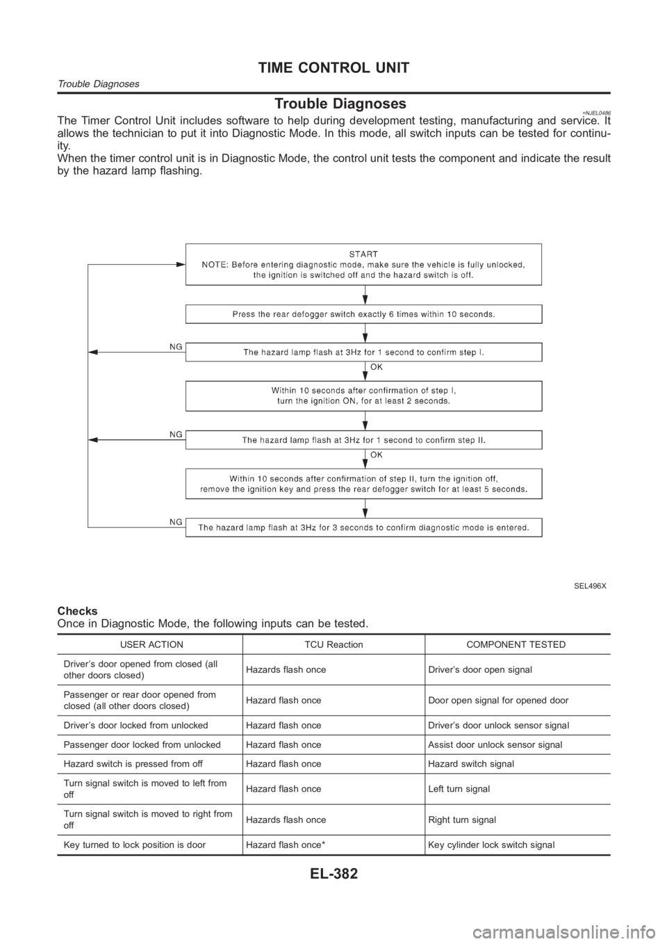
Trouble Diagnoses=NJEL0486The Timer Control Unit includes software to help during development testing, manufacturing and service. It
allows the technician to put it into Diagnostic Mode. In this mode, all switch inputs can be tested for continu-
ity.
When the timer control unit is in Diagnostic Mode, the control unit tests the component and indicate the result
by the hazard lamp flashing.
SEL496X
Checks
Once in Diagnostic Mode, the following inputs can be tested.
USER ACTION TCU Reaction COMPONENT TESTED
Driver’s door opened from closed (all
other doors closed)Hazards flash once Driver’s door open signal
Passenger or rear door opened from
closed (all other doors closed)Hazard flash once Door open signal for opened door
Driver’s door locked from unlocked Hazard flash once Driver’s door unlocksensor signal
Passenger door locked from unlocked Hazard flash once Assist door unlock sensor signal
Hazard switch is pressed from off Hazard flash once Hazard switch signal
Turn signal switch is moved to left from
offHazard flash once Left turn signal
Turn signal switch is moved to right from
offHazards flash once Right turn signal
Key turned to lock position is door Hazard flash once* Key cylinder lock switch signal
TIME CONTROL UNIT
Trouble Diagnoses
EL-382
Page 2719 of 3189
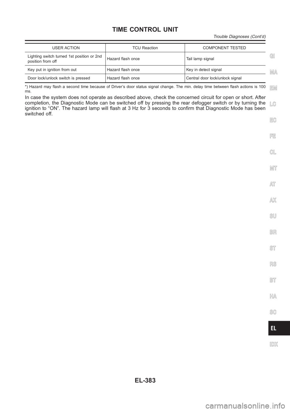
USER ACTION TCU Reaction COMPONENT TESTED
Lighting switch turned 1st position or 2nd
position from offHazard flash once Tail lamp signal
Key put in ignition from out Hazard flash once Key in detect signal
Door lock/unlock switch is pressed Hazard flash once Central door lock/unlock signal
*) Hazard may flash a second time because of Driver’s door status signal change. The min. delay time between flash actions is 100
ms.
In case the system does not operate as described above, check the concernedcircuit for open or short. After
completion, the Diagnostic Mode can be switched off by pressing the rear defogger switch or by turning the
ignition to “ON”. The hazard lamp will flash at 3 Hz for 3 seconds to confirm that Diagnostic Mode has been
switched off.
GI
MA
EM
LC
EC
FE
CL
MT
AT
AX
SU
BR
ST
RS
BT
HA
SC
IDX
TIME CONTROL UNIT
Trouble Diagnoses (Cont’d)
EL-383
Page 2720 of 3189
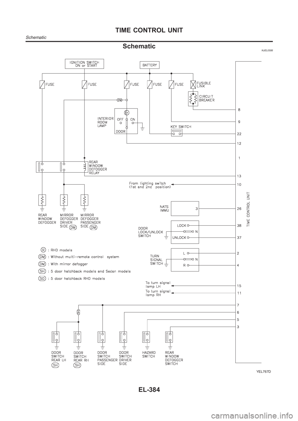
SchematicNJEL0506
YEL767D
TIME CONTROL UNIT
Schematic
EL-384