NISSAN ALMERA N16 2003 Electronic Repair Manual
ALMERA N16 2003
NISSAN
NISSAN
https://www.carmanualsonline.info/img/5/57350/w960_57350-0.png
NISSAN ALMERA N16 2003 Electronic Repair Manual
Trending: service reset, ATC, tow, fuse diagram, gauge, brake, open hood
Page 2671 of 3189
KEY SWITCH CHECKNJEL0581S09
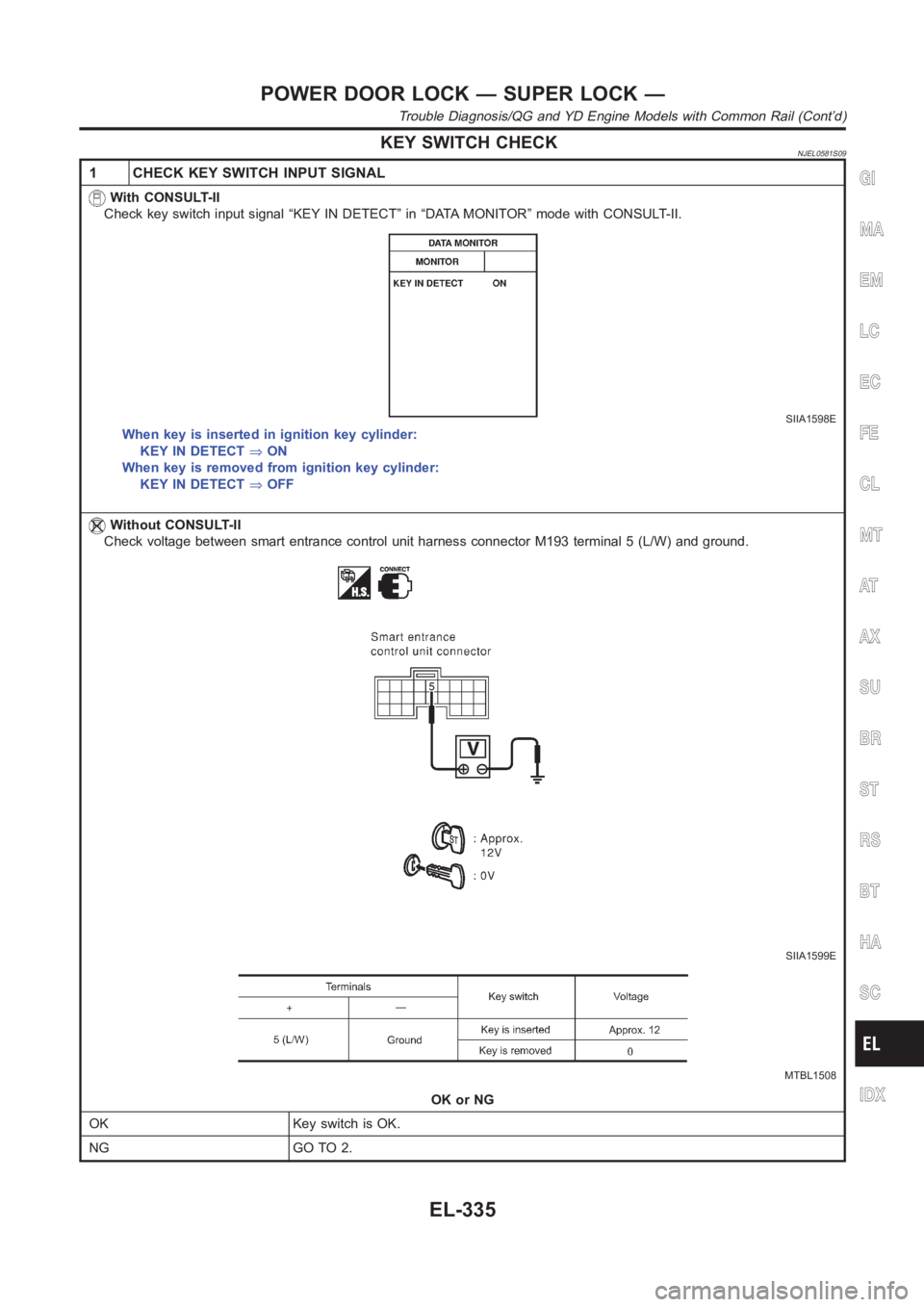
1 CHECK KEY SWITCH INPUT SIGNAL
With CONSULT-II
Check key switch input signal “KEY IN DETECT” in “DATA MONITOR” mode with CONSULT-II.
SIIA1598E
When key is inserted in ignition key cylinder:
KEY IN DETECT⇒ON
When key is removed from ignition key cylinder:
KEY IN DETECT⇒OFF
Without CONSULT-II
Check voltage between smart entrance control unit harness connector M193terminal 5 (L/W) and ground.
SIIA1599E
MTBL1508
OK or NG
OK Key switch is OK.
NG GO TO 2.
GI
MA
EM
LC
EC
FE
CL
MT
AT
AX
SU
BR
ST
RS
BT
HA
SC
IDX
POWER DOOR LOCK — SUPER LOCK —
Trouble Diagnosis/QG and YD Engine Models with Common Rail (Cont’d)
EL-335
Page 2672 of 3189
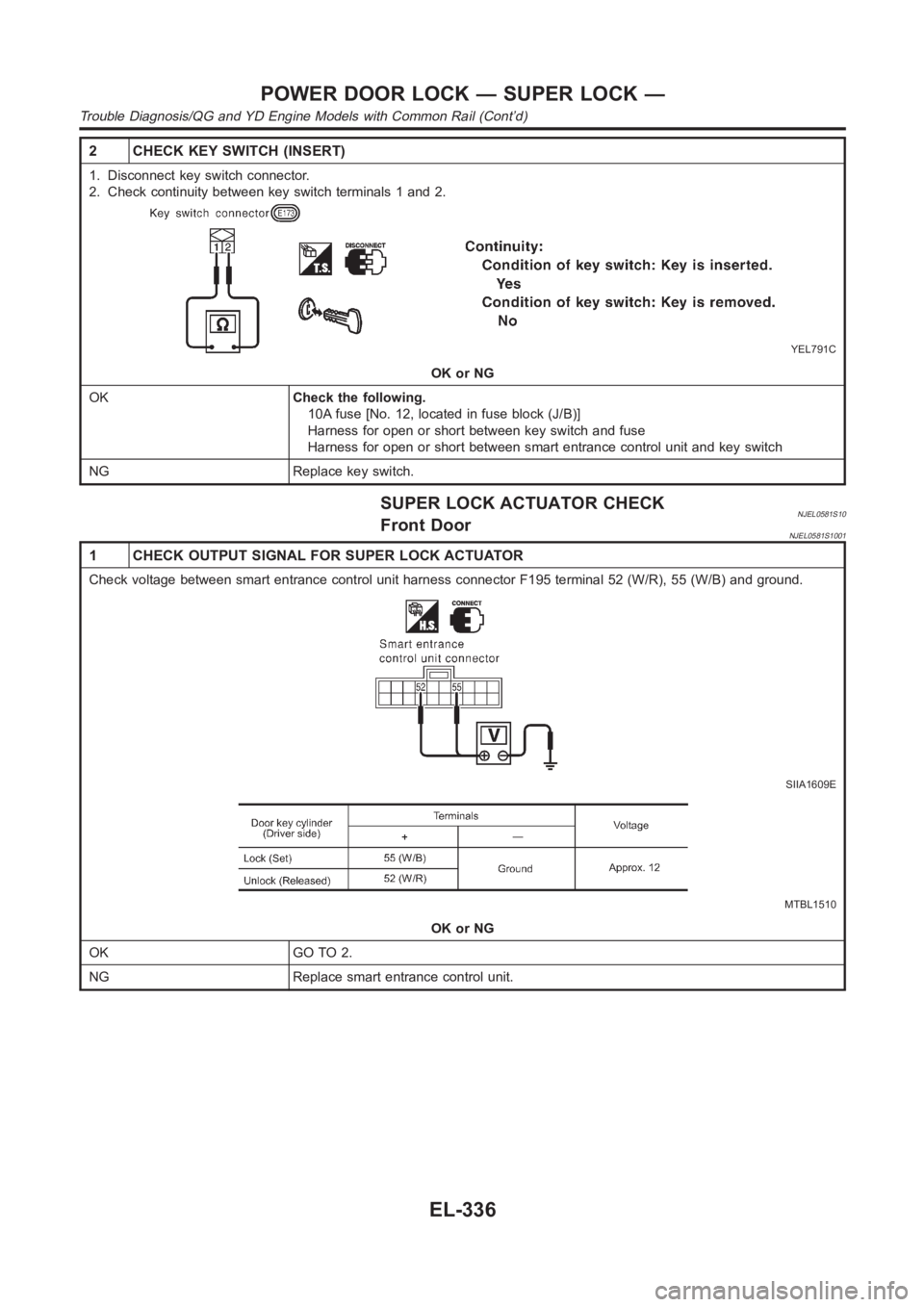
2 CHECK KEY SWITCH (INSERT)
1. Disconnect key switch connector.
2. Check continuity between key switch terminals 1 and 2.
YEL791C
OK or NG
OKCheck the following.
10A fuse [No. 12, located in fuse block (J/B)]
Harness for open or short between key switch and fuse
Harness for open or short between smart entrance control unit and key switch
NG Replace key switch.
SUPER LOCK ACTUATOR CHECKNJEL0581S10Front DoorNJEL0581S1001
1 CHECK OUTPUT SIGNAL FOR SUPER LOCK ACTUATOR
Check voltage between smart entrance control unit harness connector F195terminal 52 (W/R), 55 (W/B) and ground.
SIIA1609E
MTBL1510
OK or NG
OK GO TO 2.
NG Replace smart entrance control unit.
POWER DOOR LOCK — SUPER LOCK —
Trouble Diagnosis/QG and YD Engine Models with Common Rail (Cont’d)
EL-336
Page 2673 of 3189
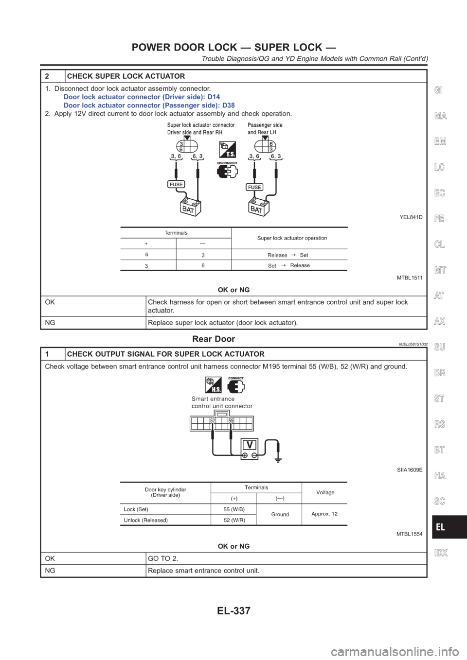
2 CHECK SUPER LOCK ACTUATOR
1. Disconnect door lock actuator assembly connector.
Door lock actuator connector (Driver side): D14
Door lock actuator connector (Passenger side): D38
2. Apply 12V direct current to door lock actuator assembly and check operation.
YEL841D
MTBL1511
OK or NG
OK Check harness for open or short between smart entrance control unit and super lock
actuator.
NG Replace super lock actuator (door lock actuator).
Rear DoorNJEL0581S1002
1 CHECK OUTPUT SIGNAL FOR SUPER LOCK ACTUATOR
Check voltage between smart entrance control unit harness connector M195terminal 55 (W/B), 52 (W/R) and ground.
SIIA1609E
MTBL1554
OK or NG
OK GO TO 2.
NG Replace smart entrance control unit.
GI
MA
EM
LC
EC
FE
CL
MT
AT
AX
SU
BR
ST
RS
BT
HA
SC
IDX
POWER DOOR LOCK — SUPER LOCK —
Trouble Diagnosis/QG and YD Engine Models with Common Rail (Cont’d)
EL-337
Page 2674 of 3189
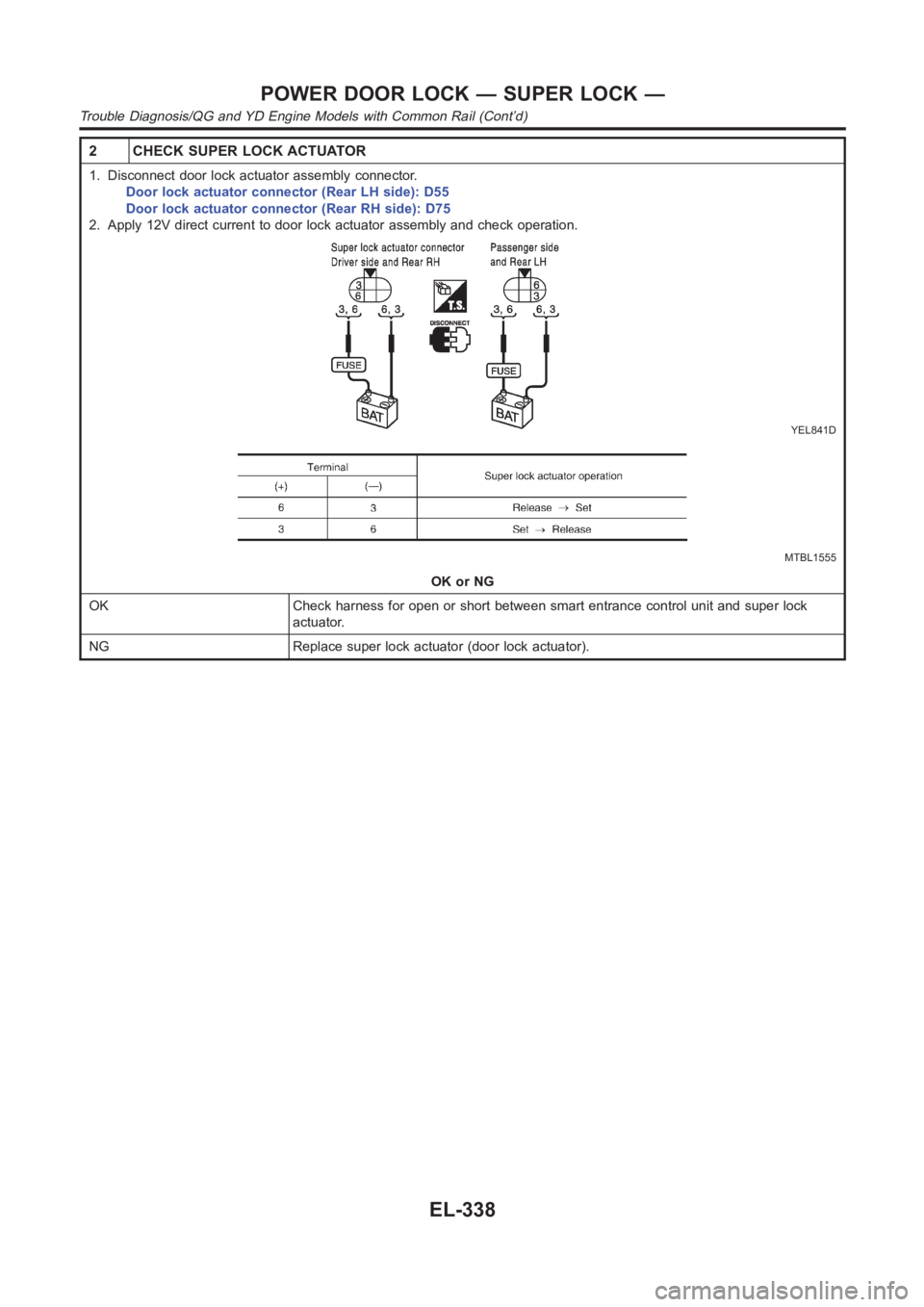
2 CHECK SUPER LOCK ACTUATOR
1. Disconnect door lock actuator assembly connector.
Door lock actuator connector (Rear LH side): D55
Door lock actuator connector (Rear RH side): D75
2. Apply 12V direct current to door lock actuator assembly and check operation.
YEL841D
MTBL1555
OK or NG
OK Check harness for open or short between smart entrance control unit and super lock
actuator.
NG Replace super lock actuator (door lock actuator).
POWER DOOR LOCK — SUPER LOCK —
Trouble Diagnosis/QG and YD Engine Models with Common Rail (Cont’d)
EL-338
Page 2675 of 3189
Trouble Diagnoses/YD Engine Models without
Common Rail and K9K Engine Models
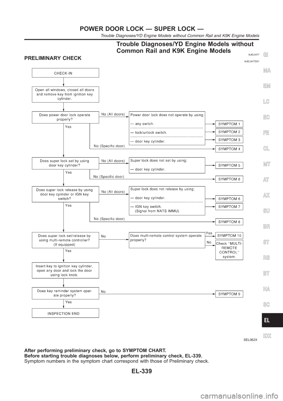
NJEL0477PRELIMINARY CHECKNJEL0477S01
SEL062X
After performing preliminary check, go to SYMPTOM CHART.
Before starting trouble diagnoses below, perform preliminary check, EL-339.
Symptom numbers in the symptom chart correspond with those of Preliminarycheck.
GI
MA
EM
LC
EC
FE
CL
MT
AT
AX
SU
BR
ST
RS
BT
HA
SC
IDX
POWER DOOR LOCK — SUPER LOCK —
Trouble Diagnoses/YD Engine Models without Common Rail and K9K Engine Models
EL-339
Page 2676 of 3189
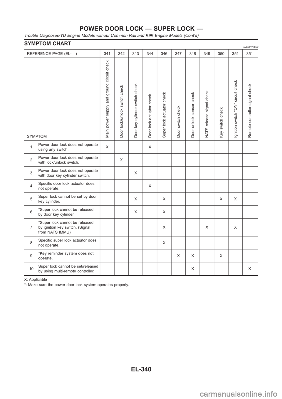
SYMPTOM CHARTNJEL0477S02
REFERENCE PAGE (EL- ) 341 342 343 344 346 347 348 349 350 351 351
SYMPTOM
Main power supply and ground circuit check
Door lock/unlock switch check
Door key cylinder switch check
Door lock actuator check
Super lock actuator check
Door switch check
Door unlock sensor check
NATS release signal check
Key switch check
Ignition switch “ON” circuit check
Remote controller signal check
1Power door lock does not operate
using any switch.XX
2Power door lock does not operate
with lock/unlock switch.X
3Power door lock does not operate
with door key cylinder switch.X
4Specific door lock actuator does
not operate.X
5Super lock cannot be set by door
key cylinder.XX XX
6*Super lock cannot be released
by door key cylinder.XX
7*Super lock cannot be released
by ignition key switch. (Signal
from NATS IMMU)XXX
8Specific super lock actuator does
not operate.X
9*Key reminder system does not
operate.XX X
10Super lock cannot be set/released
by using multi-remote controller.XX
X: Applicable
*: Make sure the power door lock system operates properly.
POWER DOOR LOCK — SUPER LOCK —
Trouble Diagnoses/YD Engine Models without Common Rail and K9K Engine Models (Cont’d)
EL-340
Page 2677 of 3189
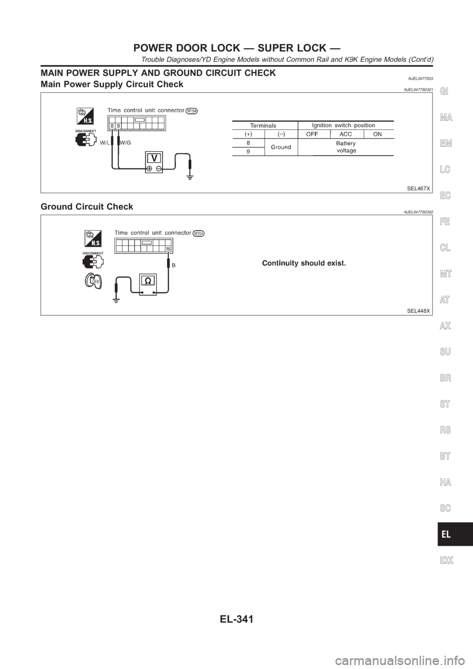
MAIN POWER SUPPLY AND GROUND CIRCUIT CHECKNJEL0477S03Main Power Supply Circuit CheckNJEL0477S0301
SEL467X
Ground Circuit CheckNJEL0477S0302
SEL448X
GI
MA
EM
LC
EC
FE
CL
MT
AT
AX
SU
BR
ST
RS
BT
HA
SC
IDX
POWER DOOR LOCK — SUPER LOCK —
Trouble Diagnoses/YD Engine Models without Common Rail and K9K Engine Models (Cont’d)
EL-341
Page 2678 of 3189
DOOR LOCK/UNLOCK SWITCH CHECK=NJEL0477S04
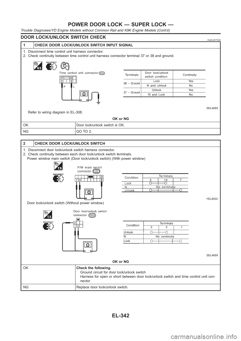
1 CHECK DOOR LOCK/UNLOCK SWITCH INPUT SIGNAL
1. Disconnect time control unit harness connector.
2. Check continuity between time control unit harness connector terminal37 or 38 and ground.
SEL468X
Refer to wiring diagram in EL-308.
OK or NG
OK Door lock/unlock switch is OK.
NG GO TO 2.
2 CHECK DOOR LOCK/UNLOCK SWITCH
1. Disconnect door lock/unlock switch harness connector.
2. Check continuity between each door lock/unlock switch terminals.
Power window main switch (Door lock/unlock switch) (With power window)
YEL803C
Door lock/unlock switch (Without power window)
SEL469X
OK or NG
OKCheck the following.
Ground circuit for door lock/unlock switch
Harness for open or short between door lock/unlock switch and time controlunit con-
nector
NG Replace door lock/unlock switch.
POWER DOOR LOCK — SUPER LOCK —
Trouble Diagnoses/YD Engine Models without Common Rail and K9K Engine Models (Cont’d)
EL-342
Page 2679 of 3189
DOOR KEY CYLINDER SWITCH CHECKNJEL0477S05
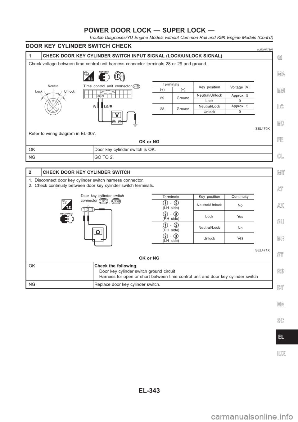
1 CHECK DOOR KEY CYLINDER SWITCH INPUT SIGNAL (LOCK/UNLOCK SIGNAL)
Check voltage between time control unit harness connector terminals 28 or29 and ground.
SEL470X
Refer to wiring diagram in EL-307.
OK or NG
OK Door key cylinder switch is OK.
NG GO TO 2.
2 CHECK DOOR KEY CYLINDER SWITCH
1. Disconnect door key cylinder switch harness connector.
2. Check continuity between door key cylinder switch terminals.
SEL471X
OK or NG
OKCheck the following.
Door key cylinder switch ground circuit
Harness for open or short between time control unit and door key cylinder switch
NG Replace door key cylinder switch.
GI
MA
EM
LC
EC
FE
CL
MT
AT
AX
SU
BR
ST
RS
BT
HA
SC
IDX
POWER DOOR LOCK — SUPER LOCK —
Trouble Diagnoses/YD Engine Models without Common Rail and K9K Engine Models (Cont’d)
EL-343
Page 2680 of 3189
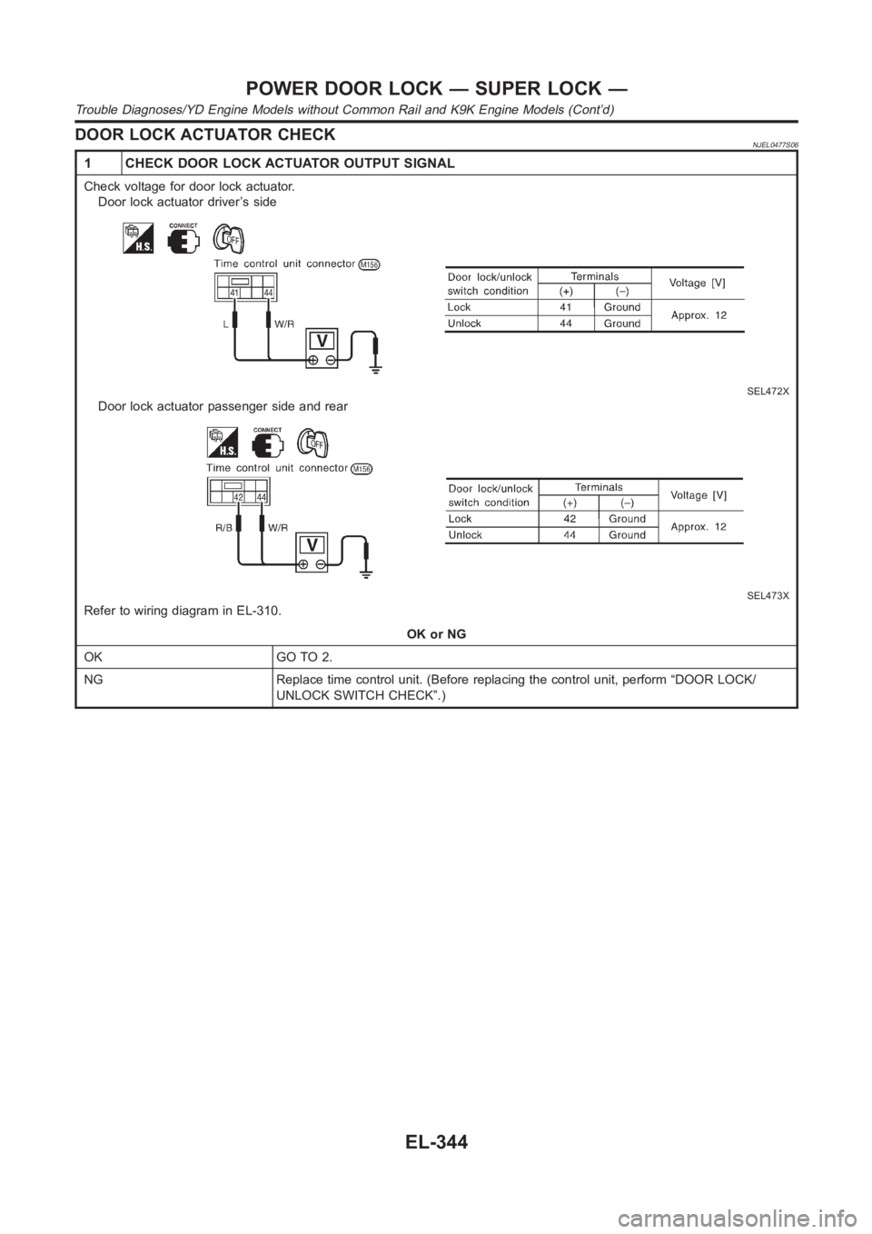
DOOR LOCK ACTUATOR CHECKNJEL0477S06
1 CHECK DOOR LOCK ACTUATOR OUTPUT SIGNAL
Check voltage for door lock actuator.
Door lock actuator driver’s side
SEL472X
Door lock actuator passenger side and rear
SEL473X
Refer to wiring diagram in EL-310.
OK or NG
OK GO TO 2.
NG Replace time control unit. (Before replacing the control unit, perform“DOOR LOCK/
UNLOCK SWITCH CHECK”.)
POWER DOOR LOCK — SUPER LOCK —
Trouble Diagnoses/YD Engine Models without Common Rail and K9K Engine Models (Cont’d)
EL-344
Trending: buttons, filter, navigation, headlamp, lights, service, drain bolt
