NISSAN ALMERA N16 2003 Electronic Repair Manual
Manufacturer: NISSAN, Model Year: 2003, Model line: ALMERA N16, Model: NISSAN ALMERA N16 2003Pages: 3189, PDF Size: 54.76 MB
Page 2731 of 3189
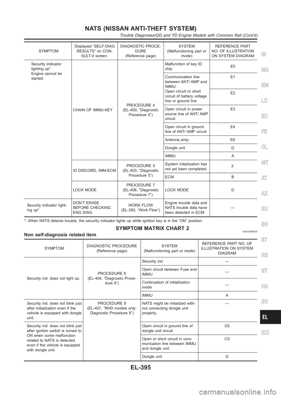
SYMPTOMDisplayed “SELF-DIAG
RESULTS” on CON-
SULT-II screen.DIAGNOSTIC PROCE-
DURE
(Reference page)SYSTEM
(Malfunctioning part or
mode)REFERENCE PART
NO. OF ILLUSTRATION
ON SYSTEM DIAGRAM
Security indicator
lighting up*
Engine cannot be
started
CHAIN OF IMMU-KEYPROCEDURE 4
(EL-400, “Diagnostic
Procedure 4”)Malfunction of key ID
chipE5
Communication line
between ANT/ AMP and
IMMU:
Open circuit or short
circuit of battery voltage
line or ground lineE1
E2
Open circuit in power
source line of ANT/ AMP
circuitE3
Open circuit in ground
line of ANT/ AMP circuitE4
Antenna amp. E6
Dongle unit G
IMMU A
ID DISCORD, IMM-ECMPROCEDURE 5
(EL-403, “Diagnostic
Procedure 5”)System initialization has
not yet been completed.F
ECM B
LOCK MODEPROCEDURE 7
(EL-406, “Diagnostic
Procedure 7”)LOCK MODE D
Security indicator light-
ing up*DON’T ERASE
BEFORE CHECKING
ENG DIAGWORK FLOW
(EL-393, “Work Flow”)Engine trouble data and
NATS trouble data have
been detected in ECM—
*: When NATS detects trouble, the security indicator lights up while ignition key is in the “ON” position.
SYMPTOM MATRIX CHART 2NJEL0590S03Non self-diagnosis related item
SYMPTOMDIAGNOSTIC PROCEDURE
(Reference page)SYSTEM
(Malfunctioning part or mode)REFERENCE PART NO. OF
ILLUSTRATION ON SYSTEM
DIAGRAM
Security ind. does not light up.PROCEDURE 6
(EL-404, “Diagnostic Proce-
dure 6”)Security ind. —
Open circuit between Fuse and
IMMU—
Continuation of initialization
mode—
IMMU A
Security ind. does not blink just
after initialization even if the
vehicle is equipped with dongle
unit.PROCEDURE 8
(EL-407, “RHD models only:
Diagnostic Procedure 8”)NATS might be initialized with-
out connecting dongle unit
properly.—
Security ind. does not blink just
after ignition switch is turned to
ON when some malfunction
related to NATS is detected
even if the vehicle is equipped
with dongle unit.Open circuit in ground line of
dongle unit circuitC6
Open or short circuit in com-
munication line between IMMU
and dongle unitC5
Dongle unit G
GI
MA
EM
LC
EC
FE
CL
MT
AT
AX
SU
BR
ST
RS
BT
HA
SC
IDX
NATS (NISSAN ANTI-THEFT SYSTEM)
Trouble Diagnoses/QG and YD Engine Models with Common Rail (Cont’d)
EL-395
Page 2732 of 3189
SYMPTOMDIAGNOSTIC PROCEDURE
(Reference page)SYSTEM
(Malfunctioning part or mode)REFERENCE PART NO. OF
ILLUSTRATION ON SYSTEM
DIAGRAM
Security ind. dose not blink just
after ignition switch is turned to
ON.
Engine can not be started*PROCEDURE 9
(EL-408, “Diagnostic Proce-
dure 9”)Open or short circuit starter
motor between smart entrance
control unit—
*: CONSULT-II Self-diagnostic results display screen “no malfunction isdetected”.
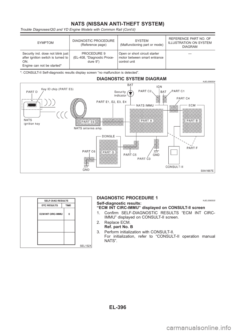
DIAGNOSTIC SYSTEM DIAGRAMNJEL0590S04
SIIA1667E
SEL152X
DIAGNOSTIC PROCEDURE 1NJEL0590S05Self-diagnostic results:
“ECM INT CIRC-IMMU” displayed on CONSULT-II screen
1. Confirm SELF-DIAGNOSTIC RESULTS “ECM INT CIRC-
IMMU” displayed on CONSULT-II screen.
2. Replace ECM.
Ref. part No. B
3. Perform initialization with CONSULT-II.
For initialization, refer to “CONSULT-II operation manual
NATS”.
NATS (NISSAN ANTI-THEFT SYSTEM)
Trouble Diagnoses/QG and YD Engine Models with Common Rail (Cont’d)
EL-396
Page 2733 of 3189
DIAGNOSTIC PROCEDURE 2=NJEL0590S06Self-diagnostic results:
“CHAIN OF ECM-IMMU” displayed on CONSULT-II screen
1 CONFIRM SELF-DIAGNOSTIC RESULTS
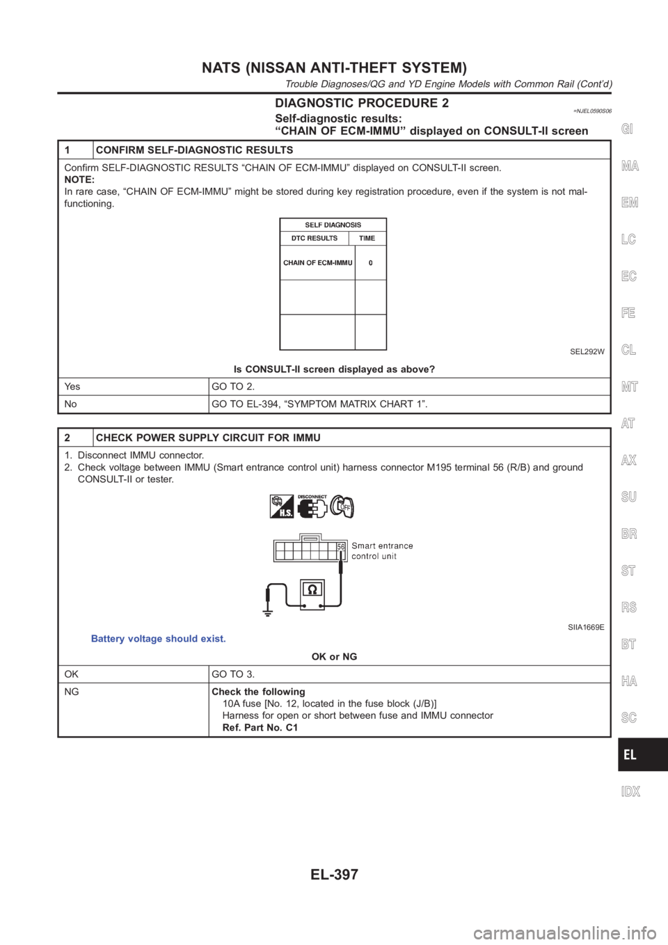
Confirm SELF-DIAGNOSTIC RESULTS “CHAIN OF ECM-IMMU” displayed on CONSULT-II screen.
NOTE:
In rare case, “CHAIN OF ECM-IMMU” might be stored during key registration procedure, even if the system is not mal-
functioning.
SEL292W
Is CONSULT-II screen displayed as above?
Ye s G O T O 2 .
No GO TO EL-394, “SYMPTOM MATRIX CHART 1”.
2 CHECK POWER SUPPLY CIRCUIT FOR IMMU
1. Disconnect IMMU connector.
2. Check voltage between IMMU (Smart entrance control unit) harness connector M195 terminal 56 (R/B) and ground
CONSULT-II or tester.
SIIA1669E
Battery voltage should exist.
OK or NG
OK GO TO 3.
NGCheck the following
10A fuse [No. 12, located in the fuse block (J/B)]
Harness for open or short between fuse and IMMU connector
Ref. Part No. C1
GI
MA
EM
LC
EC
FE
CL
MT
AT
AX
SU
BR
ST
RS
BT
HA
SC
IDX
NATS (NISSAN ANTI-THEFT SYSTEM)
Trouble Diagnoses/QG and YD Engine Models with Common Rail (Cont’d)
EL-397
Page 2734 of 3189
3 CHECK IGN SW. ON SIGNAL
1. Turn ignition switch ON.
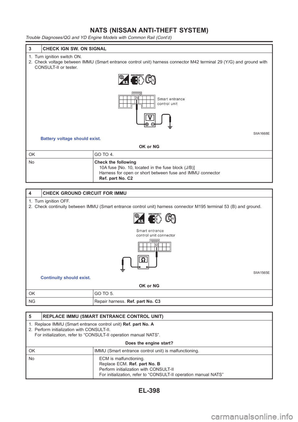
2. Check voltage between IMMU (Smart entrance control unit) harness connector M42 terminal 29 (Y/G) and ground with
CONSULT-II or tester.
SIIA1668E
Battery voltage should exist.
OK or NG
OK GO TO 4.
NoCheck the following
10A fuse [No. 10, located in the fuse block (J/B)]
Harness for open or short between fuse and IMMU connector
Ref. part No. C2
4 CHECK GROUND CIRCUIT FOR IMMU
1. Turn ignition OFF.
2. Check continuity between IMMU (Smart entrance control unit) harness connector M195 terminal 53 (B) and ground.
SIIA1565E
Continuity should exist.
OK or NG
OK GO TO 5.
NG Repair harness.Ref. part No. C3
5 REPLACE IMMU (SMART ENTRANCE CONTROL UNIT)
1. Replace IMMU (Smart entrance control unit)Ref. part No. A
2. Perform initialization with CONSULT-II.
For initialization, refer to “CONSULT-II operation manual NATS”.
Does the engine start?
OK IMMU (Smart entrance control unit) is malfunctioning.
No ECM is malfunctioning.
Replace ECM.Ref. part No. B
Perform initialization with CONSULT-II
For initialization, refer to “CONSULT-II operation manual NATS”
NATS (NISSAN ANTI-THEFT SYSTEM)
Trouble Diagnoses/QG and YD Engine Models with Common Rail (Cont’d)
EL-398
Page 2735 of 3189
DIAGNOSTIC PROCEDURE 3NJEL0590S07Self-diagnostic results:
“DIFFERENCE OF KEY” displayed on CONSULT-II screen
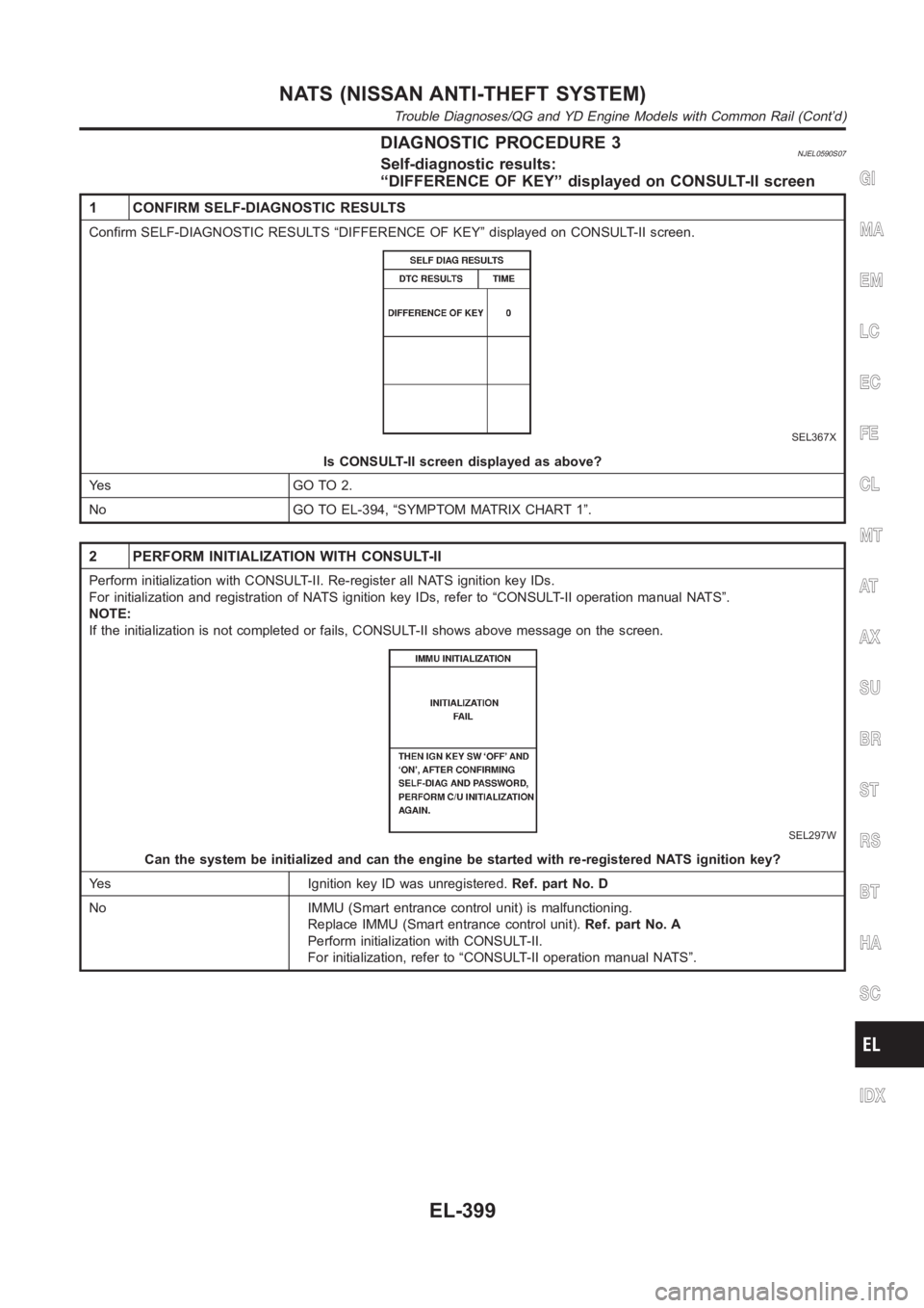
1 CONFIRM SELF-DIAGNOSTIC RESULTS
Confirm SELF-DIAGNOSTIC RESULTS “DIFFERENCE OF KEY” displayed on CONSULT-II screen.
SEL367X
Is CONSULT-II screen displayed as above?
Ye s G O T O 2 .
No GO TO EL-394, “SYMPTOM MATRIX CHART 1”.
2 PERFORM INITIALIZATION WITH CONSULT-II
Perform initialization with CONSULT-II. Re-register all NATS ignition key IDs.
For initialization and registration of NATS ignition key IDs, refer to “CONSULT-II operation manual NATS”.
NOTE:
If the initialization is not completed or fails, CONSULT-II shows above message on the screen.
SEL297W
Can the system be initialized and can the engine be started with re-registered NATS ignition key?
Yes Ignition key ID was unregistered.Ref. part No. D
No IMMU (Smart entrance control unit) is malfunctioning.
Replace IMMU (Smart entrance control unit).Ref. part No. A
Perform initialization with CONSULT-II.
For initialization, refer to “CONSULT-II operation manual NATS”.
GI
MA
EM
LC
EC
FE
CL
MT
AT
AX
SU
BR
ST
RS
BT
HA
SC
IDX
NATS (NISSAN ANTI-THEFT SYSTEM)
Trouble Diagnoses/QG and YD Engine Models with Common Rail (Cont’d)
EL-399
Page 2736 of 3189
DIAGNOSTIC PROCEDURE 4=NJEL0590S08Self-diagnostic results:
“CHAIN OF IMMU-KEY” displayed on CONSULT-II screen
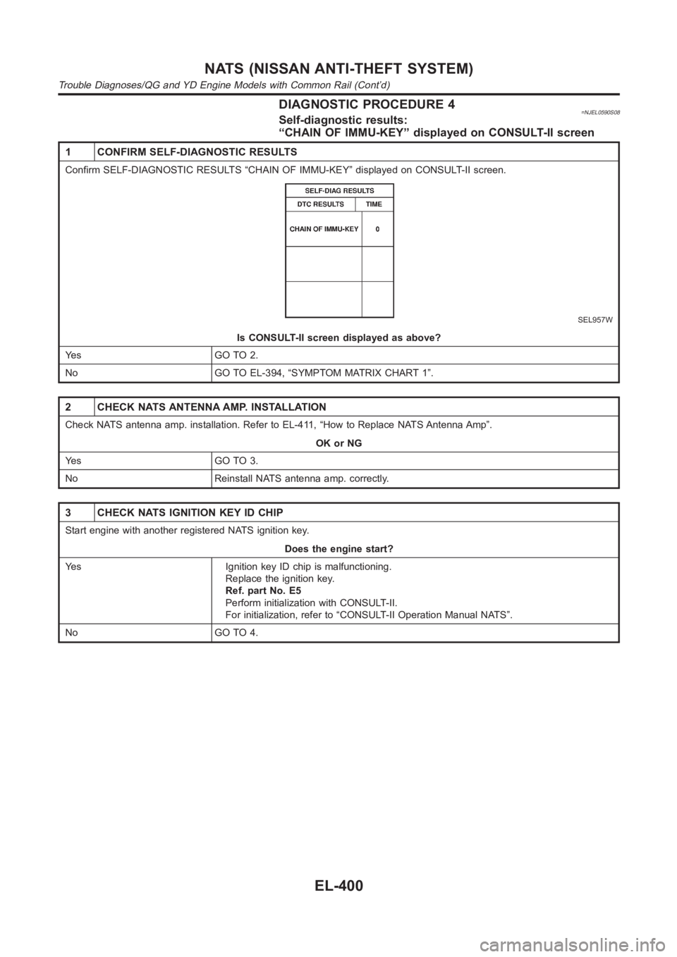
1 CONFIRM SELF-DIAGNOSTIC RESULTS
Confirm SELF-DIAGNOSTIC RESULTS “CHAIN OF IMMU-KEY” displayed on CONSULT-II screen.
SEL957W
Is CONSULT-II screen displayed as above?
Ye s G O T O 2 .
No GO TO EL-394, “SYMPTOM MATRIX CHART 1”.
2 CHECK NATS ANTENNA AMP. INSTALLATION
Check NATS antenna amp. installation. Refer to EL-411, “How to Replace NATS Antenna Amp”.
OK or NG
Ye s G O T O 3 .
No Reinstall NATS antenna amp. correctly.
3 CHECK NATS IGNITION KEY ID CHIP
Start engine with another registered NATS ignition key.
Does the engine start?
Yes Ignition key ID chip is malfunctioning.
Replace the ignition key.
Ref. part No. E5
Perform initialization with CONSULT-II.
For initialization, refer to “CONSULT-II Operation Manual NATS”.
No GO TO 4.
NATS (NISSAN ANTI-THEFT SYSTEM)
Trouble Diagnoses/QG and YD Engine Models with Common Rail (Cont’d)
EL-400
Page 2737 of 3189
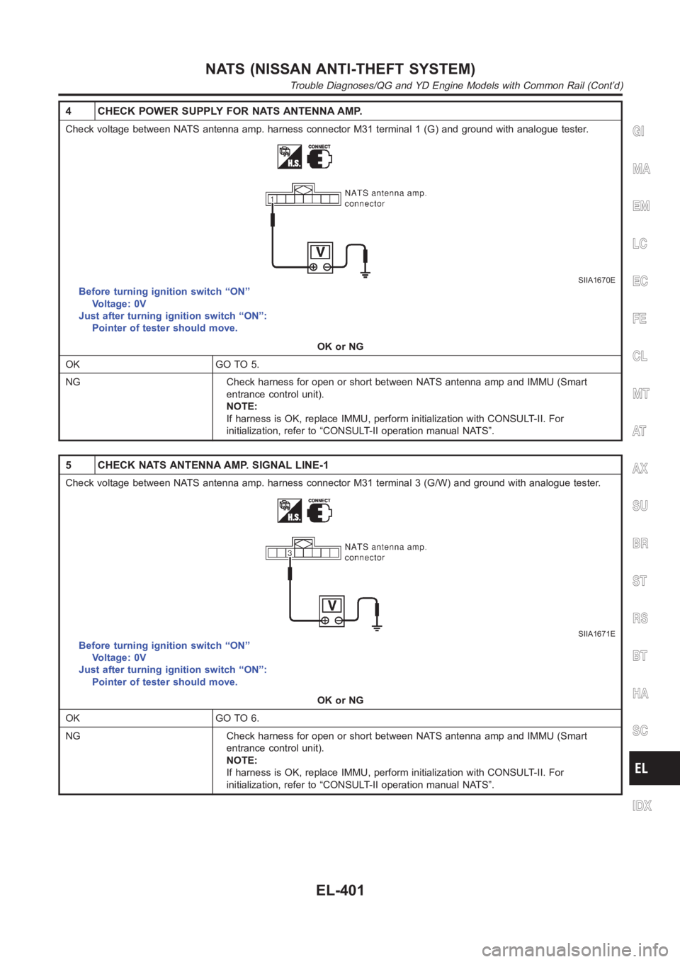
4 CHECK POWER SUPPLY FOR NATS ANTENNA AMP.
Check voltage between NATS antenna amp. harness connector M31 terminal 1 (G) and ground with analogue tester.
SIIA1670E
Before turning ignition switch “ON”
Voltage: 0V
Just after turning ignition switch “ON”:
Pointer of tester should move.
OK or NG
OK GO TO 5.
NG Check harness for open or short between NATS antenna amp and IMMU (Smart
entrance control unit).
NOTE:
If harness is OK, replace IMMU, perform initialization with CONSULT-II. For
initialization, refer to “CONSULT-II operation manual NATS”.
5 CHECK NATS ANTENNA AMP. SIGNAL LINE-1
Check voltage between NATS antenna amp. harness connector M31 terminal 3 (G/W) and ground with analogue tester.
SIIA1671E
Before turning ignition switch “ON”
Voltage: 0V
Just after turning ignition switch “ON”:
Pointer of tester should move.
OK or NG
OK GO TO 6.
NG Check harness for open or short between NATS antenna amp and IMMU (Smart
entrance control unit).
NOTE:
If harness is OK, replace IMMU, perform initialization with CONSULT-II. For
initialization, refer to “CONSULT-II operation manual NATS”.
GI
MA
EM
LC
EC
FE
CL
MT
AT
AX
SU
BR
ST
RS
BT
HA
SC
IDX
NATS (NISSAN ANTI-THEFT SYSTEM)
Trouble Diagnoses/QG and YD Engine Models with Common Rail (Cont’d)
EL-401
Page 2738 of 3189
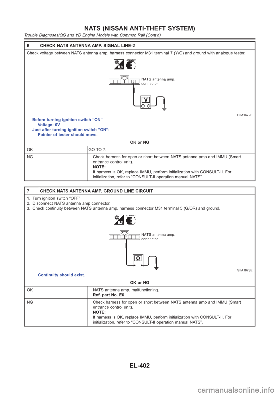
6 CHECK NATS ANTENNA AMP. SIGNAL LINE-2
Check voltage between NATS antenna amp. harness connector M31 terminal 7 (Y/G) and ground with analogue tester.
SIIA1672E
Before turning ignition switch “ON”
Voltage: 0V
Just after turning ignition switch “ON”:
Pointer of tester should move.
OK or NG
OK GO TO 7.
NG Check harness for open or short between NATS antenna amp and IMMU (Smart
entrance control unit).
NOTE:
If harness is OK, replace IMMU, perform initialization with CONSULT-II. For
initialization, refer to “CONSULT-II operation manual NATS”.
7 CHECK NATS ANTENNA AMP. GROUND LINE CIRCUIT
1. Turn ignition switch “OFF”
2. Disconnect NATS antenna amp connector.
3. Check continuity between NATS antenna amp. harness connector M31 terminal 5 (G/OR) and ground.
SIIA1673E
Continuity should exist.
OK or NG
OK NATS antenna amp. malfunctioning.
Ref. part No. E6
NG Check harness for open or short between NATS antenna amp and IMMU (Smart
entrance control unit).
NOTE:
If harness is OK, replace IMMU, perform initialization with CONSULT-II. For
initialization, refer to “CONSULT-II operation manual NATS”.
NATS (NISSAN ANTI-THEFT SYSTEM)
Trouble Diagnoses/QG and YD Engine Models with Common Rail (Cont’d)
EL-402
Page 2739 of 3189
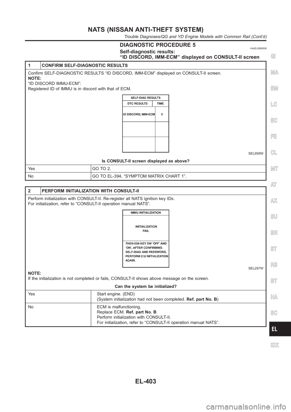
DIAGNOSTIC PROCEDURE 5=NJEL0590S09Self-diagnostic results:
“ID DISCORD, IMM-ECM” displayed on CONSULT-II screen
1 CONFIRM SELF-DIAGNOSTIC RESULTS
Confirm SELF-DIAGNOSTIC RESULTS “ID DISCORD, IMM-ECM” displayed on CONSULT-II screen.
NOTE:
“ID DISCORD IMMU-ECM”:
Registered ID of IMMU is in discord with that of ECM.
SEL958W
Is CONSULT-II screen displayed as above?
Ye s G O T O 2 .
No GO TO EL-394, “SYMPTOM MATRIX CHART 1”.
2 PERFORM INITIALIZATION WITH CONSULT-II
Perform initialization with CONSULT-II. Re-register all NATS ignition key IDs.
For initialization, refer to “CONSULT-II operation manual NATS”.
SEL297W
NOTE:
If the initialization is not completed or fails, CONSULT-II shows above message on the screen.
Can the system be initialized?
Yes Start engine. (END)
(System initialization had not been completed.Ref. part No. B)
No ECM is malfunctioning.
Replace ECM.Ref. part No. B
Perform initialization with CONSULT-II.
For initialization, refer to “CONSULT-II operation manual NATS”.
GI
MA
EM
LC
EC
FE
CL
MT
AT
AX
SU
BR
ST
RS
BT
HA
SC
IDX
NATS (NISSAN ANTI-THEFT SYSTEM)
Trouble Diagnoses/QG and YD Engine Models with Common Rail (Cont’d)
EL-403
Page 2740 of 3189
![NISSAN ALMERA N16 2003 Electronic Repair Manual DIAGNOSTIC PROCEDURE 6=NJEL0590S10“SECURITY INDICATOR LAMP DOES NOT LIGHT UP”
1 CHECK FUSE
Check 10A fuse [No. 12 and No. 30, located in the fuse block (J/B)]
10A fuse OK?
OK GO TO 2.
NG Replace f NISSAN ALMERA N16 2003 Electronic Repair Manual DIAGNOSTIC PROCEDURE 6=NJEL0590S10“SECURITY INDICATOR LAMP DOES NOT LIGHT UP”
1 CHECK FUSE
Check 10A fuse [No. 12 and No. 30, located in the fuse block (J/B)]
10A fuse OK?
OK GO TO 2.
NG Replace f](/img/5/57350/w960_57350-2739.png)
DIAGNOSTIC PROCEDURE 6=NJEL0590S10“SECURITY INDICATOR LAMP DOES NOT LIGHT UP”
1 CHECK FUSE
Check 10A fuse [No. 12 and No. 30, located in the fuse block (J/B)]
10A fuse OK?
OK GO TO 2.
NG Replace fuse.
2 CHECK SECURITY INDICATOR LAMP
1. Install 10A fuse.
2. Perform initialization with CONSULT-II.
For initialization, refer to “CONSULT-II Operation Manual NATS”.
3. Turn ignition switch OFF.
4. Start engine and turn ignition switch OFF.
5. Check the security indicator lamp lighting.
Security indicator lamp should be light up.
OK or NG
OK INSPECTION END.
NG GO TO 3.
3 CHECK SECURITY INDICATOR LAMP POWER SUPPLY CIRCUIT
1. Disconnect combination meter connector.
2. Check voltage between combination meter harness connector M171 terminal 34 and ground.
YEL842D
Battery voltage should exist.
OK or NG
OK GO TO 4.
NG Check harness for open or short between fuse and security indicator lamp.
NATS (NISSAN ANTI-THEFT SYSTEM)
Trouble Diagnoses/QG and YD Engine Models with Common Rail (Cont’d)
EL-404