NISSAN ALMERA N16 2003 Electronic Repair Manual
Manufacturer: NISSAN, Model Year: 2003, Model line: ALMERA N16, Model: NISSAN ALMERA N16 2003Pages: 3189, PDF Size: 54.76 MB
Page 2701 of 3189
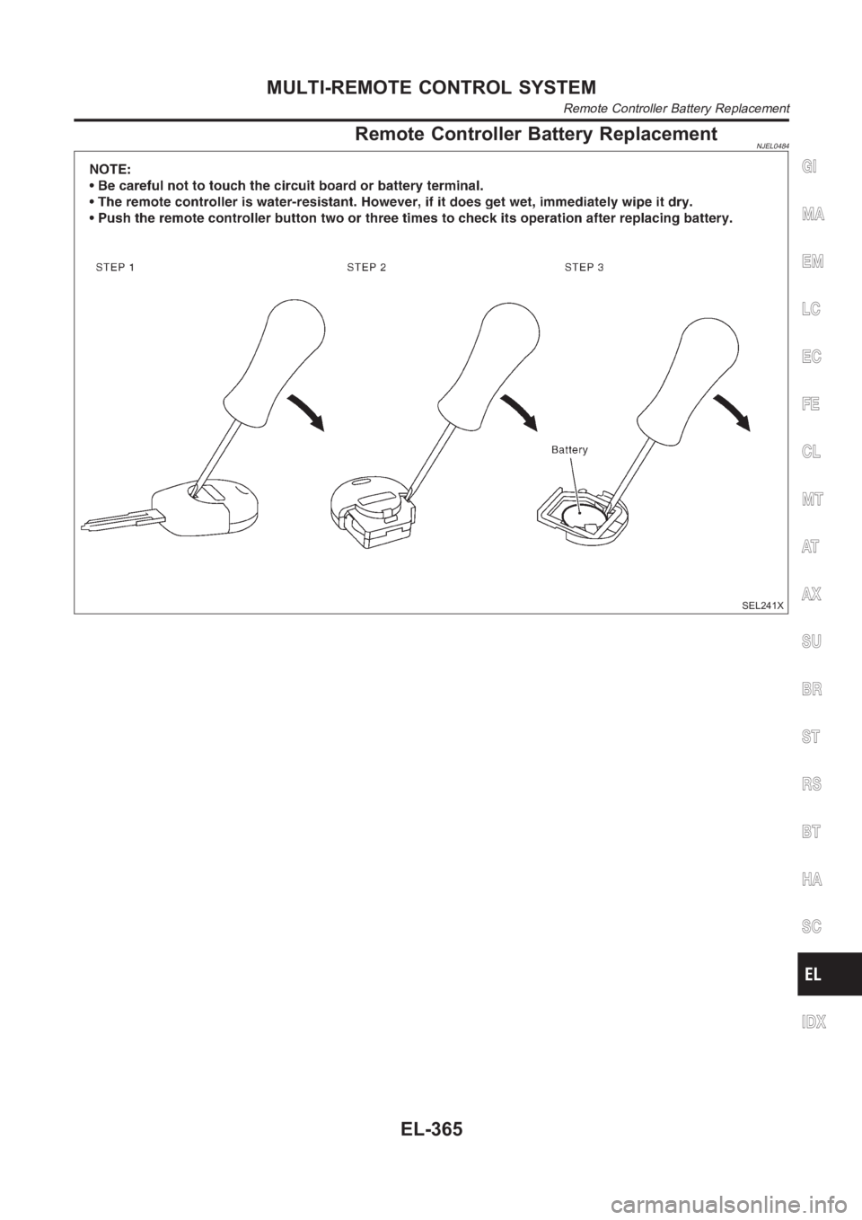
Remote Controller Battery ReplacementNJEL0484
SEL241X
GI
MA
EM
LC
EC
FE
CL
MT
AT
AX
SU
BR
ST
RS
BT
HA
SC
IDX
MULTI-REMOTE CONTROL SYSTEM
Remote Controller Battery Replacement
EL-365
Page 2702 of 3189
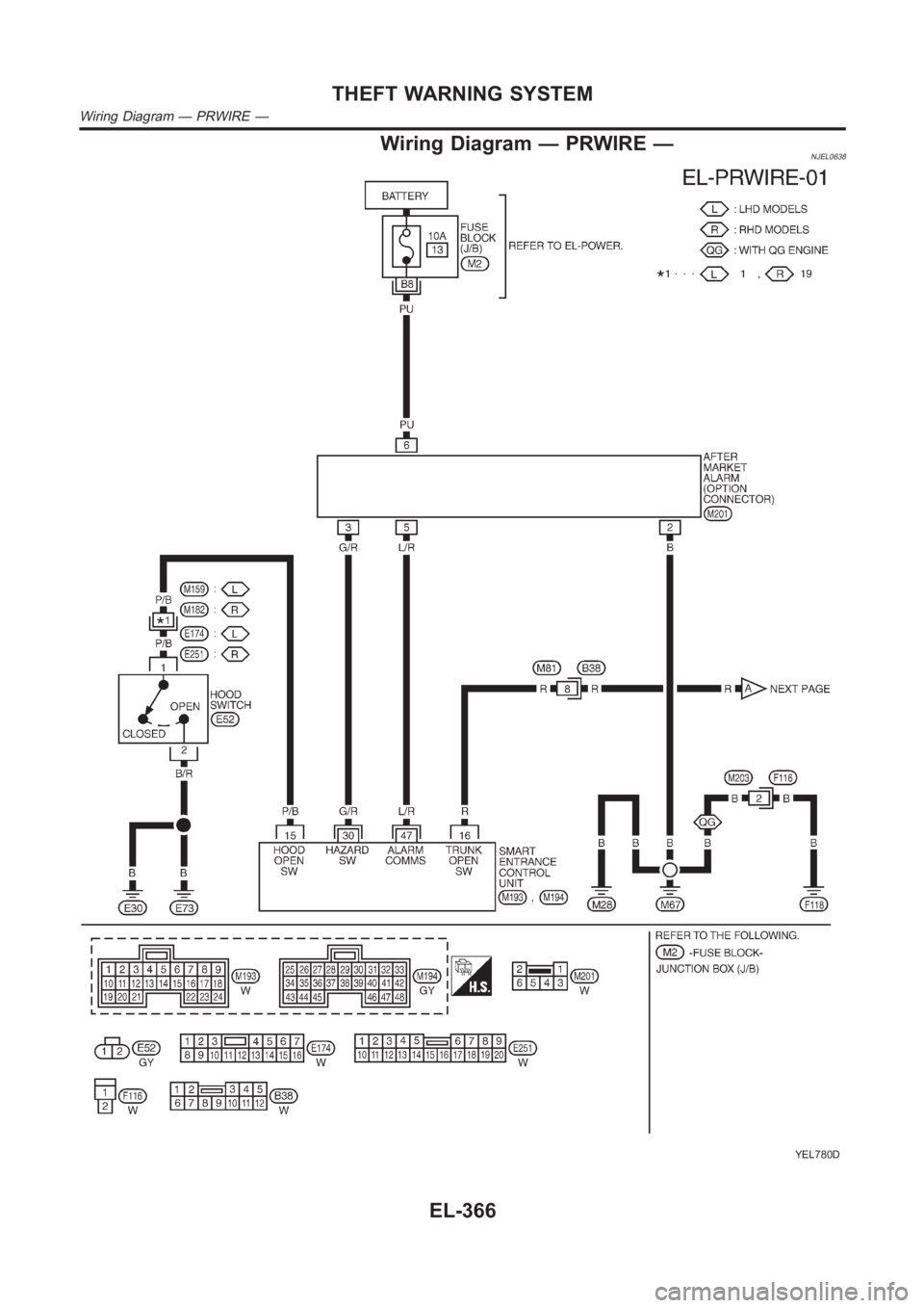
Wiring Diagram — PRWIRE —NJEL0638
YEL780D
THEFT WARNING SYSTEM
Wiring Diagram — PRWIRE —
EL-366
Page 2703 of 3189
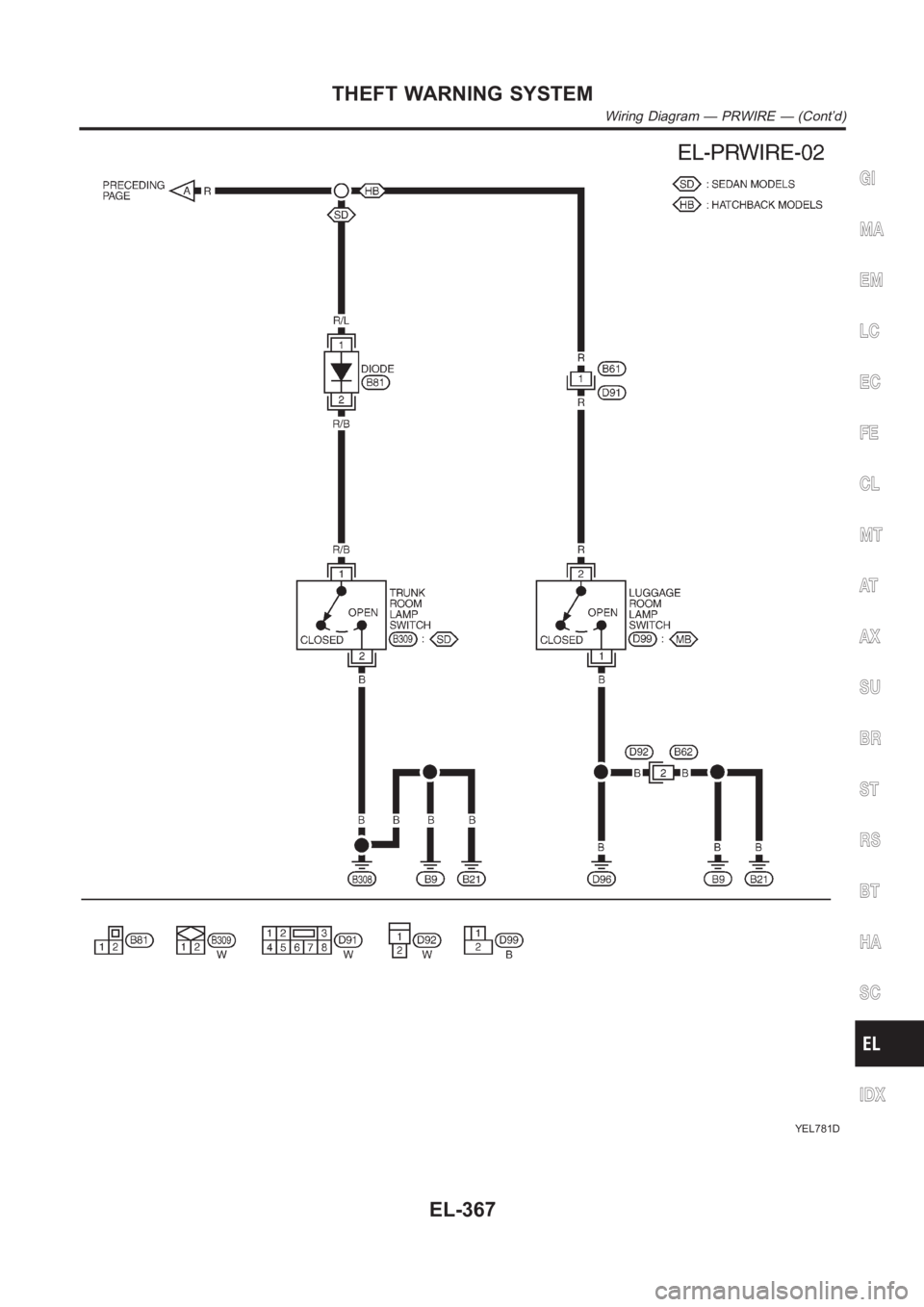
YEL781D
GI
MA
EM
LC
EC
FE
CL
MT
AT
AX
SU
BR
ST
RS
BT
HA
SC
IDX
THEFT WARNING SYSTEM
Wiring Diagram — PRWIRE — (Cont’d)
EL-367
Page 2704 of 3189
DescriptionNJEL0583The Smart Entrance Control Unit is applied for QG engine models and YD engine models with common rail.
OUTLINENJEL0583S01The smart entrance control unit totally controls the following body electrical system operations.
Warning chime, refer to EL-136, “WARNING CHIME”.
Rear defogger and door mirror defogger, refer to EL-173, “REAR WINDOW DEFOGGER”.
Power door lock, refer to EL-261, “POWER DOOR LOCK SYSTEM”.
Power door lock - Super lock - (RHD models), refer to EL-301, “POWER DOOR LOCK — SUPER LOCK
—”.
Multi-remote control system, refer to EL-352, “MULTI-REMOTE CONTROL SYSTEM”.
NATS (Nissan Anti-Theft system), refer to EL-386, “NATS (NISSAN ANTI-THEFT SYSTEM)”.
Interior lamp, refer to EL-80, “INTERIOR ROOM LAMP”.
Also, smart entrance control unit has the “sleep/wake-up control” function. Smart entrance control unit puts
itself (the whole smart entrance control unit) to sleep under certain conditions to prevent unnecessary power
consumption. Then, when a certain input is detected, the system wakes itself up. For more detailed
information, refer to EL-368, “SLEEP/WAKE-UP CONTROL”.
INTERIOR LAMP/SPOT LAMP/VANITY MIRROR ILLUMINATIONNJEL0583S02The lamps turn off automatically when the interior lamp, spot lamp or/and vanity mirror illumination are illumi-
nated with the ignition key in the OFF position, if the lamp remains lit by the door switch open signal or if the
lamp switch is in the ON position for more than 30 minutes.
After lamps are turned off by the smart entrance control unit, the lamps illuminate again when:
Driver’s door is locked or unlocked with remote controller, door lock/unlock switch or door key cylinder.
Ignition switch is turned to ON.
Door is opened or closed,
Key is inserted into ignition key cylinder.
REAR WINDOW DEFOGGER/DOOR MIRROR DEFOGGERNJEL0583S03Rear window defogger is turned off in approximately 15 minutes after the rear window defogger switch is turned
on.
SLEEP/WAKE-UP CONTROLNJEL0583S04Sleep ControlNJEL0583S0401“Sleep” control prevents unnecessary power consumption. After the following conditions are met, the smart
entrance control unit suspends the operation. The whole smart entrance control unit is set in the “sleep” mode.
Ignition switch “OFF”
All electrical loads (in the smart entrance control unit) “OFF”
Timer “OFF”
Each switch do not input
Wake-up ControlNJEL0583S0402When the smart entrance control unit detects a “wake-up” signal, it wakes up the whole system and starts
operating again. When any one of the following switches are turned ON, the “sleep” mode is canceled:
Ignition switch
Hazard switch
Headlamp switch
Hood switch
Trunk room lamp switch (sedan models)
Back door switch (hatchback or wagon models)
Each door switch
Trunk release switch (sedan models)
Back door release switch (hatchback or wagon models)
External trunk release switch (sedan models)
External back door release switch (hatchback or wagon models)
SMART ENTRANCE CONTROL SYSTEM
Description
EL-368
Page 2705 of 3189
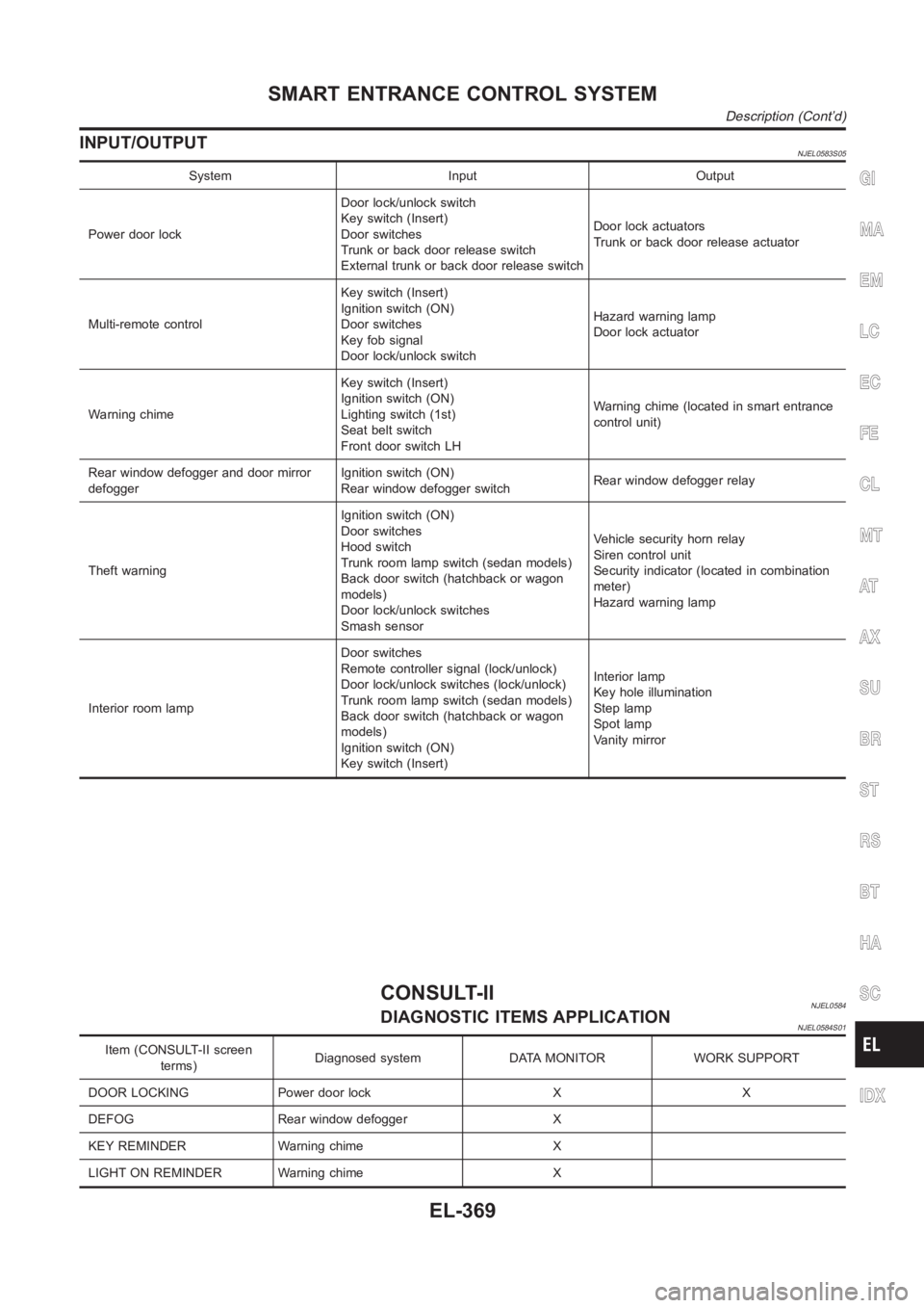
INPUT/OUTPUTNJEL0583S05
System Input Output
Power door lockDoor lock/unlock switch
Key switch (Insert)
Door switches
Trunk or back door release switch
External trunk or back door release switchDoor lock actuators
Trunk or back door release actuator
Multi-remote controlKey switch (Insert)
Ignition switch (ON)
Door switches
Key fob signal
Door lock/unlock switchHazard warning lamp
Door lock actuator
Warning chimeKey switch (Insert)
Ignition switch (ON)
Lighting switch (1st)
Seat belt switch
Front door switch LHWarning chime (located in smart entrance
control unit)
Rear window defogger and door mirror
defoggerIgnition switch (ON)
Rear window defogger switchRear window defogger relay
Theft warningIgnition switch (ON)
Door switches
Hood switch
Trunk room lamp switch (sedan models)
Back door switch (hatchback or wagon
models)
Door lock/unlock switches
Smash sensorVehicle security horn relay
Siren control unit
Security indicator (located in combination
meter)
Hazard warning lamp
Interior room lampDoor switches
Remote controller signal (lock/unlock)
Door lock/unlock switches (lock/unlock)
Trunk room lamp switch (sedan models)
Back door switch (hatchback or wagon
models)
Ignition switch (ON)
Key switch (Insert)Interior lamp
Key hole illumination
Step lamp
Spot lamp
Vanity mirror
CONSULT-IINJEL0584DIAGNOSTIC ITEMS APPLICATIONNJEL0584S01
Item (CONSULT-II screen
terms)Diagnosed system DATA MONITOR WORK SUPPORT
DOOR LOCKING Power door lock X X
DEFOG Rear window defogger X
KEY REMINDER Warning chime X
LIGHT ON REMINDER Warning chime X
GI
MA
EM
LC
EC
FE
CL
MT
AT
AX
SU
BR
ST
RS
BT
HA
SC
IDX
SMART ENTRANCE CONTROL SYSTEM
Description (Cont’d)
EL-369
Page 2706 of 3189
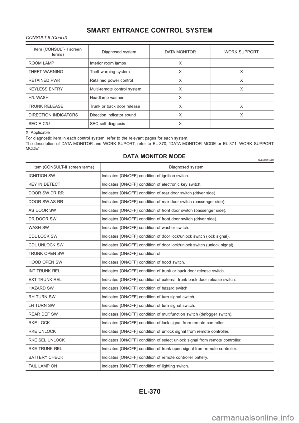
Item (CONSULT-II screen
terms)Diagnosed system DATA MONITOR WORK SUPPORT
ROOM LAMP Interior room lamps X
THEFT WARNING Theft warning system X X
RETAINED PWR Retained power control X X
KEYLESS ENTRY Multi-remote control system X X
H/L WASH Headlamp washer X
TRUNK RELEASE Trunk or back door release X X
DIRECTION INDICATORS Direction indicator sound X X
SEC-E C/U SEC self-diagnosis X
X: Applicable
For diagnostic item in each control system, refer to the relevant pages foreach system.
The description of DATA MONITOR and WORK SUPORT, refer to EL-370, “DATA MONITOR MODE or EL-371, WORK SUPPORT
MODE”.
DATA MONITOR MODENJEL0584S02
Item (CONSULT-II screen terms) Diagnosed system
IGNITION SW Indicates [ON/OFF] condition of ignition switch.
KEY IN DETECT Indicates [ON/OFF] condition of electronic key switch.
DOOR SW DR RR Indicates [ON/OFF] condition of rear door switch (driver side).
DOOR SW AS RR Indicates [ON/OFF] condition of rear door switch (passenger side).
AS DOOR SW Indicates [ON/OFF] condition of front door switch (passenger side).
DR DOOR SW Indicates [ON/OFF] condition of front door switch (driver side).
WASH SW Indicates [ON/OFF] condition of washer switch.
CDL LOCK SW Indicates [ON/OFF] condition of door lock/unlock switch (locksignal).
CDL UNLOCK SW Indicates [ON/OFF] condition of door lock/unlock switch (unlock signal).
TRUNK OPEN SW Indicates [ON/OFF] condition of
HOOD OPEN SW Indicates [ON/OFF] condition of hood switch.
INT TRUNK REL· Indicates [ON/OFF] condition of trunk or back door release switch.
EXT TRUNK REL Indicates [ON/OFF] condition of external trunk back door release switch.
HAZARD SW Indicates [ON/OFF] condition of hazard switch.
RH TURN SW Indicates [ON/OFF] condition of turn signal switch.
LH TURN SW Indicates [ON/OFF] condition of turn signal switch.
REAR DEF SW Indicates [ON/OFF] condition of multifunction switch (defogger switch).
RKE LOCK Indicates [ON/OFF] condition of lock signal from remote controller.
RKE UNLOCK Indicates [ON/OFF] condition of unlock signal from remote controller.
RKE SEL UNLOCK Indicates [ON/OFF] condition of select unlock signal from remote controller.
RKE TRUNK REL Indicates [ON/OFF] condition of trunk open signal from remote controller.
BATTERY CHECK Indicates [ON/OFF] condition of remote controller battery.
TAIL LAMP ON Indicates [ON/OFF] condition of lighting switch.
SMART ENTRANCE CONTROL SYSTEM
CONSULT-II (Cont’d)
EL-370
Page 2707 of 3189
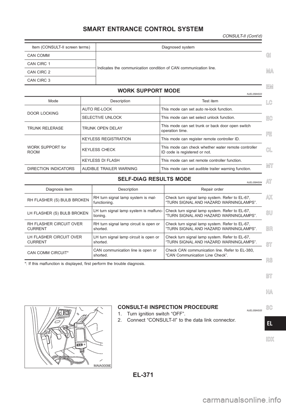
Item (CONSULT-II screen terms) Diagnosed system
CAN COMM
Indicates the communication condition of CAN communication line. CANCIRC1
CANCIRC2
CANCIRC3
WORK SUPPORT MODENJEL0584S03
Mode Description Test item
DOOR LOCKINGAUTO RE-LOCK This mode can set auto re-lock function.
SELECTIVE UNLOCK This mode can set select unlock function.
TRUNK RELERASE TRUNK OPEN DELAYThis mode can set trunk or back door open switch
operation time.
WORK SUPPORT for
ROOMKEYLESS REGISTRATION This mode can register remote controller ID.
KEYLESS CHECKThis mode can check whether water remote controller
ID code is registered or not.
KEYLESS DI FLASH This mode can set remote controller function.
DIRECTION INDICATORS AUDIBLE TRAILER WARNING This mode can set audible trailer warning function.
SELF-DIAG RESULTS MODENJEL0584S04
Diagnosis item Description Repair order
RH FLASHER (S) BULB BROKENRH turn signal lamp system is mal-
functioning.Check turn signal lamp system. Refer to EL-67,
“TURN SIGNAL AND HAZARD WARNINGLAMPS”.
LH FLASHER (S) BULB BROKENLH turn signal lamp system is malfunc-
tioning.Check turn signal lamp system. Refer to EL-67,
“TURN SIGNAL AND HAZARD WARNINGLAMPS”.
RH FLASHER CIRCUIT OVER
CURRENTRH turn signal lamp circuit is open or
shorted.Check turn signal lamp system. Refer to EL-67,
“TURN SIGNAL AND HAZARD WARNINGLAMPS”.
LH FLASHER CIRCUIT OVER
CURRENTLH turn signal lamp circuit is open or
shorted.Check turn signal lamp system. Refer to EL-67,
“TURN SIGNAL AND HAZARD WARNINGLAMPS”.
CAN COMM CIRCUIT*CAN communication line is open or
shorted.Check CAN communication line. Refer to EL-380,
“CAN Communication Line Check”.
*: If this malfunction is displayed, first perform the trouble diagnosis.
MAIA0009E
CONSULT-II INSPECTION PROCEDURENJEL0584S051. Turn ignition switch “OFF”.
2. Connect “CONSULT-II” to the data link connector.
GI
MA
EM
LC
EC
FE
CL
MT
AT
AX
SU
BR
ST
RS
BT
HA
SC
IDX
SMART ENTRANCE CONTROL SYSTEM
CONSULT-II (Cont’d)
EL-371
Page 2708 of 3189
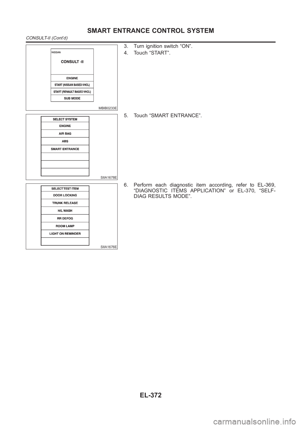
MBIB0233E
3. Turn ignition switch “ON”.
4. Touch “START”.
SIIA1678E
5. Touch “SMART ENTRANCE”.
SIIA1676E
6. Perform each diagnostic item according, refer to EL-369,
“DIAGNOSTIC ITEMS APPLICATION” or EL-370, “SELF-
DIAG RESULTS MODE”.
SMART ENTRANCE CONTROL SYSTEM
CONSULT-II (Cont’d)
EL-372
Page 2709 of 3189
NOTE:
GI
MA
EM
LC
EC
FE
CL
MT
AT
AX
SU
BR
ST
RS
BT
HA
SC
IDX
SMART ENTRANCE CONTROL SYSTEM
CONSULT-II (Cont’d)
EL-373
Page 2710 of 3189
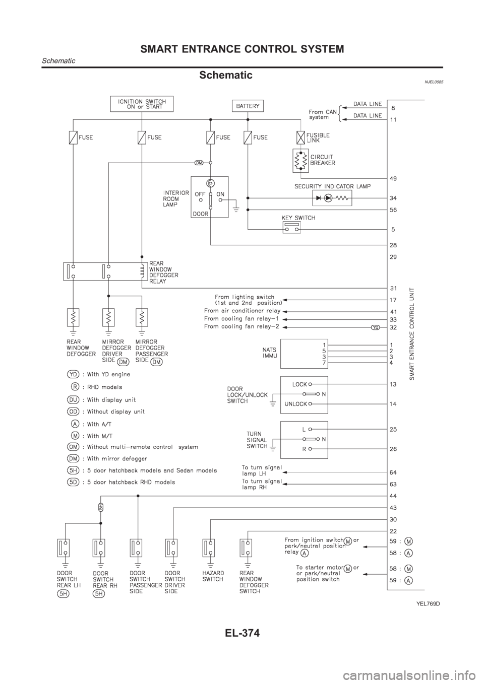
SchematicNJEL0585
YEL769D
SMART ENTRANCE CONTROL SYSTEM
Schematic
EL-374