NISSAN ALMERA N16 2003 Electronic Repair Manual
Manufacturer: NISSAN, Model Year: 2003, Model line: ALMERA N16, Model: NISSAN ALMERA N16 2003Pages: 3189, PDF Size: 54.76 MB
Page 2721 of 3189
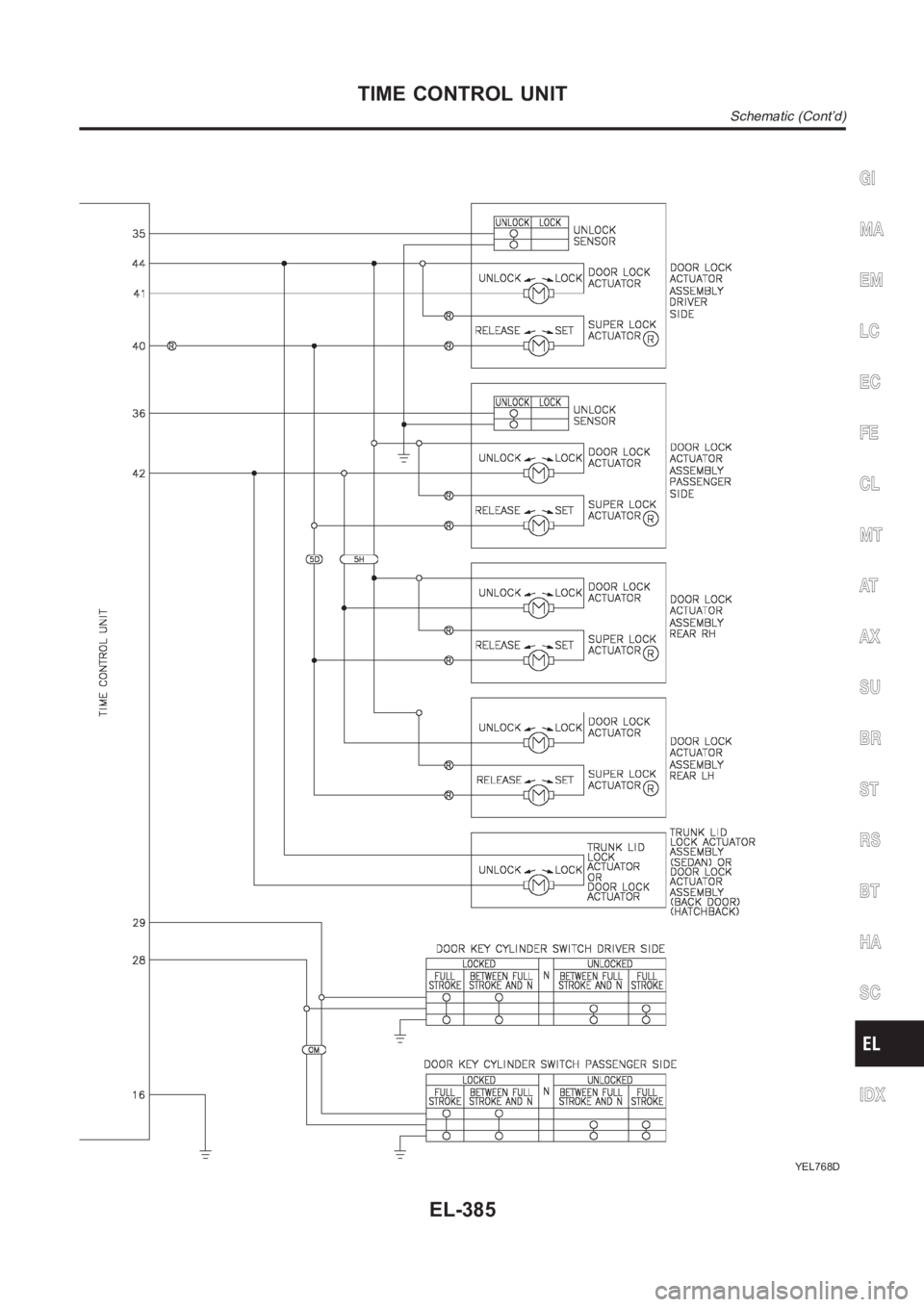
YEL768D
GI
MA
EM
LC
EC
FE
CL
MT
AT
AX
SU
BR
ST
RS
BT
HA
SC
IDX
TIME CONTROL UNIT
Schematic (Cont’d)
EL-385
Page 2722 of 3189
Component Parts and Harness Connetor
Location
NJEL0406For details, refer to “ELECTRICAL UNIT LOCATION” (EL-543) and
“HARNESS LAYOUT” (EL-550).
System DescriptionNJEL0407NATS (Nissan Anti-Theft System) has the following immobilizer functions:
Since only NATS ignition keys, whose ID nos. have been registered into the ECM and IMMU of NATS,
allow the engine to run, operation of a stolen vehicle without a NATS registered key is prevented by NATS.
That is to say, NATS will immobilize the engine if someone tries to start it without the registered key of
NATS.
This version of NATS has dongle unit to improve its anti-theft performance(RHD models for Europe).
Dongle unit has its own ID which is registered into NATS IMMU. So if dongle unit is replaced, initialization
must be carried out.
When malfunction of dongle unit is detected:
The security indicator lamp illuminates for about 15 minutes after ignition switch is turned to ON.
− When dongle unit has a malfunction and the indicator lamp is illuminated,engine can not be started.
However engine can be started only one time when security indicator lamp turns off in about 15 minutes
after ignition switch is turned to ON.
All of the originally supplied ignition key IDs have been NATS registered.
If requested by the vehicle owner, a maximum of five key IDs can be registered into the NATS compo-
nents.
The security indicator blinks when the ignition switch is in “OFF” or “ACC”position. Therefore, NATS warns
outsiders that the vehicle is equipped with the anti-theft system.
When NATS detects trouble, the security indicator lamp lights up as follows.
Condition IGN ON andWith dongle Without dongle
MIL Security indicator MIL Security indicator
NATS malfunction
(except dongle unit) is
detected—1. 6 times blinking
2. Staying ON after igni-
tion switch is turned
ON— Staying ON
Only malfunction of
dongle unit is detected.—Staying ON for about 15
minutes after ignition
switch is turned ON——
Malfunction of NATS
and engine related parts
are detected.Staying ON1. 6 times blinking
2. Staying ON after igni-
tion switch is turned
ONStaying ON Staying ON
Only engine related part
malfunction is detected.Staying ON — Staying ON —
Just after initialization of
NATS— 6 times blinking — —
NATS trouble diagnoses, system initialization and additional registration of other NATS ignition key IDs
must be carried out using CONSULT-II hardware and CONSULT-II NATS software.
Regarding the procedures of NATS initialization and NATS ignition key ID registration, refer to CONSULT-II
operation manual, NATS.
When servicing a malfunction of the NATS (indicated by lighting up of Security Indicator Lamp) or
NATS (NISSAN ANTI-THEFT SYSTEM)
Component Parts and Harness Connetor Location
EL-386
Page 2723 of 3189
registering another NATS ignition key ID no., it may be necessary to re-register original key iden-
tification. Therefore, be sure to receive ALL KEYS from vehicle owner.
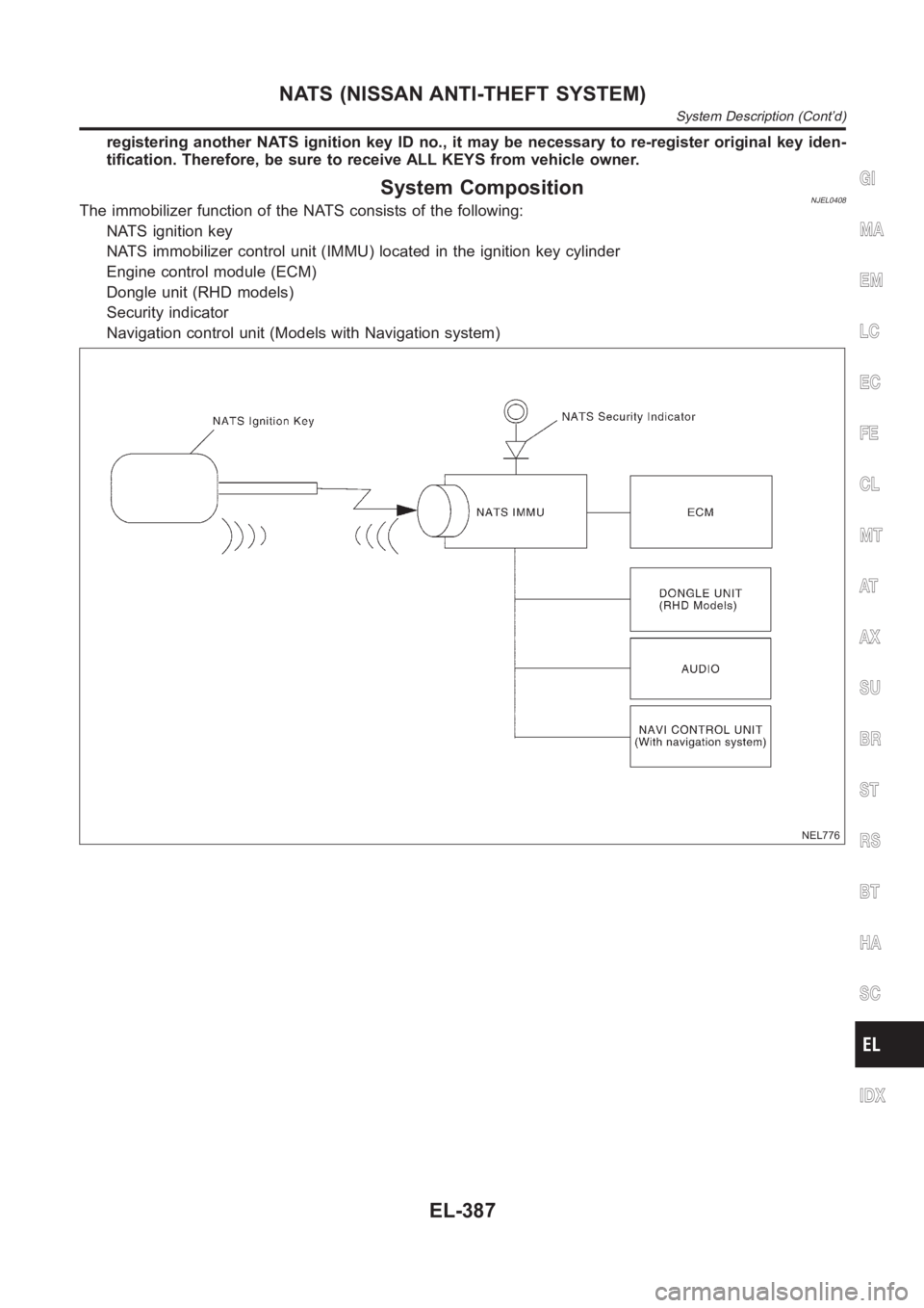
System CompositionNJEL0408The immobilizer function of the NATS consists of the following:
NATS ignition key
NATS immobilizer control unit (IMMU) located in the ignition key cylinder
Engine control module (ECM)
Dongle unit (RHD models)
Security indicator
Navigation control unit (Models with Navigation system)
NEL776
GI
MA
EM
LC
EC
FE
CL
MT
AT
AX
SU
BR
ST
RS
BT
HA
SC
IDX
NATS (NISSAN ANTI-THEFT SYSTEM)
System Description (Cont’d)
EL-387
Page 2724 of 3189
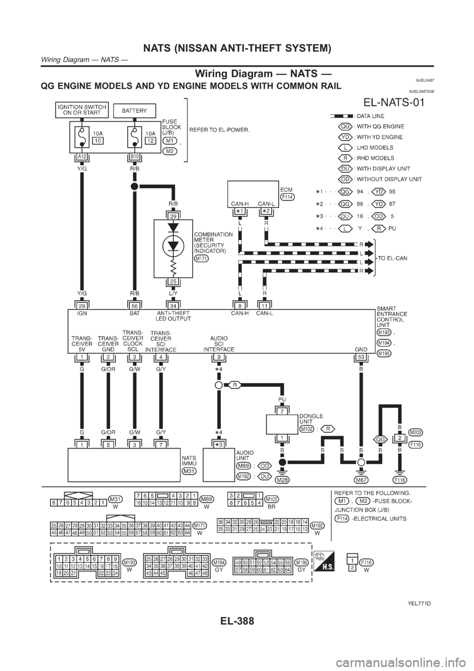
Wiring Diagram — NATS —NJEL0487QG ENGINE MODELS AND YD ENGINE MODELS WITH COMMON RAILNJEL0487S06
YEL771D
NATS (NISSAN ANTI-THEFT SYSTEM)
Wiring Diagram — NATS —
EL-388
Page 2725 of 3189
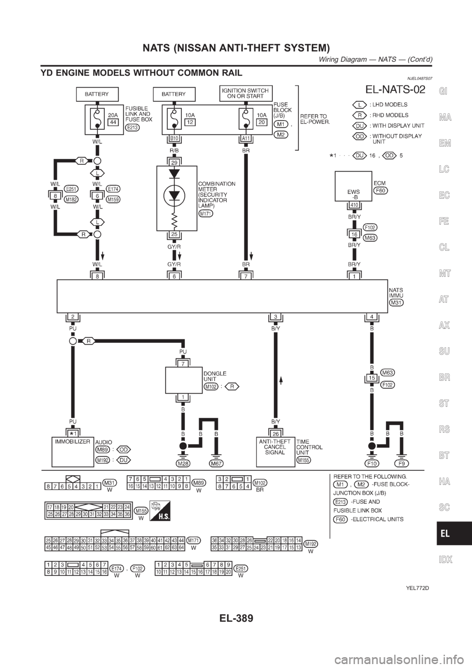
YD ENGINE MODELS WITHOUT COMMON RAILNJEL0487S07
YEL772D
GI
MA
EM
LC
EC
FE
CL
MT
AT
AX
SU
BR
ST
RS
BT
HA
SC
IDX
NATS (NISSAN ANTI-THEFT SYSTEM)
Wiring Diagram — NATS — (Cont’d)
EL-389
Page 2726 of 3189
SEF094Y
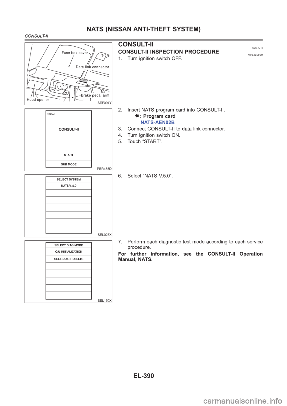
CONSULT-IINJEL0410CONSULT-II INSPECTION PROCEDURENJEL0410S011. Turn ignition switch OFF.
PBR455D
2. Insert NATS program card into CONSULT-II.
: Program card
NATS-AEN02B
3. Connect CONSULT-II to data link connector.
4. Turn ignition switch ON.
5. Touch “START”.
SEL027X
6. Select “NATS V.5.0”.
SEL150X
7. Perform each diagnostic test mode according to each service
procedure.
For further information, see the CONSULT-II Operation
Manual, NATS.
NATS (NISSAN ANTI-THEFT SYSTEM)
CONSULT-II
EL-390
Page 2727 of 3189
CONSULT-II DIAGNOSTIC TEST MODE FUNCTION=NJEL0410S02
CONSULT-II DIAGNOSTIC TEST
MODEDescription
C/U INITIALIZATION When replacing any of the following components, C/U initialization and re-registration of all
NATS ignition keys are necessary.
[NATS ignition key/IMMU/ECM/Dongle unit]
SELF-DIAG RESULTS Detected items (screen terms) are as shown in the chart EL-391.
NOTE:
When any initialization is performed, all ID previously reg-
istered will be erased and all NATS ignition keys must be
registered again.
The engine cannot be started with an unregistered key. In this
case, the system may show “DIFFERENCE OF KEY” or
“LOCK MODE” as a self-diagnostic result on the CONSULT-II
screen.
When initialization is performed for RHD models for Europe,
security indicator will flash six times to demonstrate recognition
of the dongle unit ID.
In rare case, “CHAIN OF ECM-IMMU” might be stored as a
self-diagnostic result during key registration procedure, even if
the system is not malfunctioning.
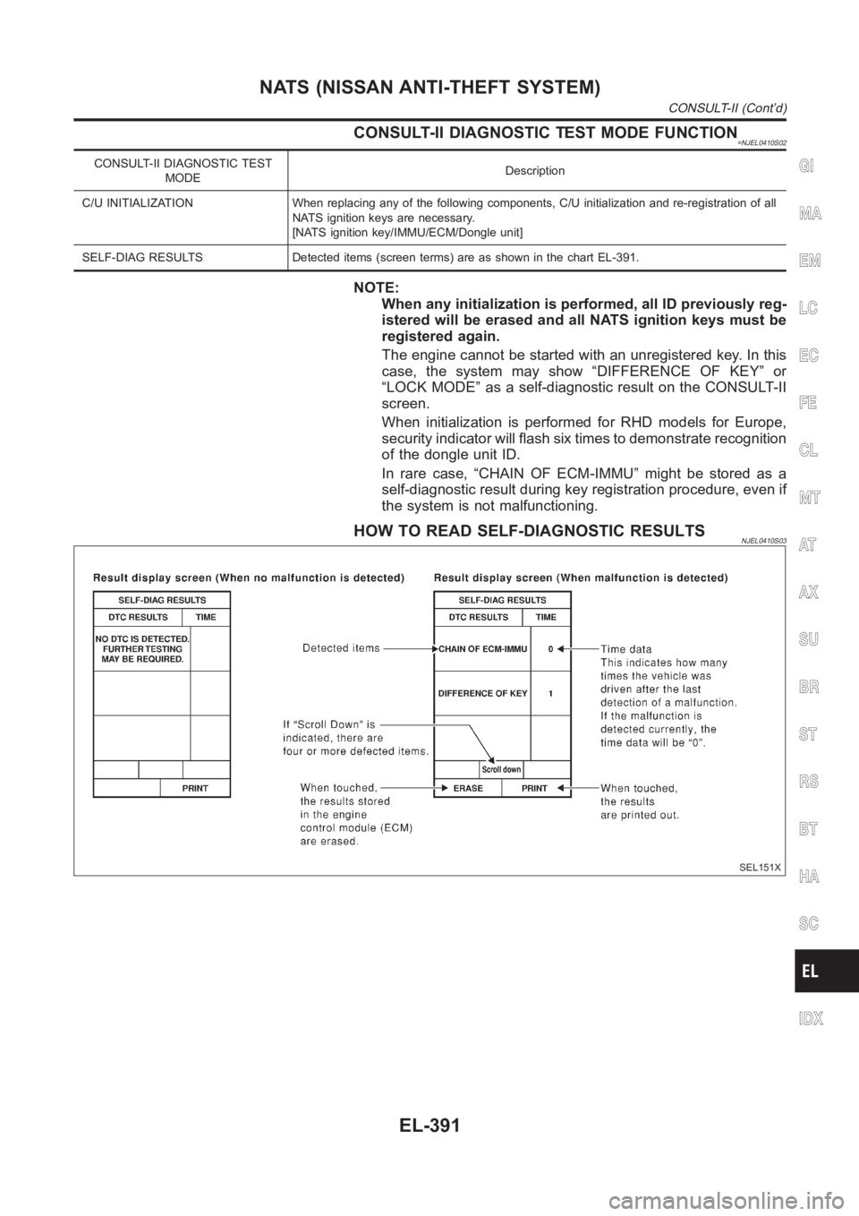
HOW TO READ SELF-DIAGNOSTIC RESULTSNJEL0410S03
SEL151X
GI
MA
EM
LC
EC
FE
CL
MT
AT
AX
SU
BR
ST
RS
BT
HA
SC
IDX
NATS (NISSAN ANTI-THEFT SYSTEM)
CONSULT-II (Cont’d)
EL-391
Page 2728 of 3189
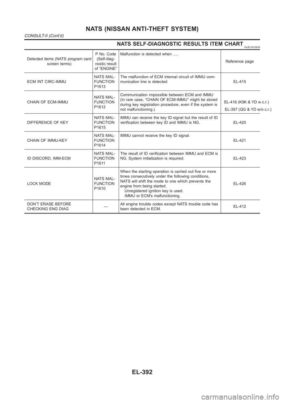
NATS SELF-DIAGNOSTIC RESULTS ITEM CHART=NJEL0410S04
Detected items (NATS program card
screen terms)P No. Code
(Self-diag-
nostic result
of “ENGINE”Malfunction is detected when .....
Reference page
ECM INT CIRC-IMMUNATS MAL-
FUNCTION
P1613The malfunction of ECM internal circuit of IMMU com-
munication line is detected. EL-415
CHAIN OF ECM-IMMUNATS MAL-
FUNCTION
P1612Communication impossible between ECM and IMMU
(In rare case, “CHAIN OF ECM-IMMU” might be stored
during key registration procedure, even if the system is
not malfunctioning.) EL-397 (QG & YD w/o c.r.) EL-416 (K9K & YD w c.r.)
DIFFERENCE OF KEYNATS MAL-
FUNCTION
P1615IMMU can receive the key ID signal but the result of ID
verification between key ID and IMMU is NG. EL-420
CHAIN OF IMMU-KEYNATS MAL-
FUNCTION
P1614IMMU cannot receive the key ID signal.
EL-421
ID DISCORD, IMM-ECMNATS MAL-
FUNCTION
P1611The result of ID verification between IMMU and ECM is
NG. System initialization is required. EL-423
LOCK MODENATS MAL-
FUNCTION
P1610When the starting operation is carried out five or more
times consecutively under the following conditions,
NATS will shift the mode to one which prevents the
engine from being started.
Unregistered ignition key is used.
IMMU or ECM’s malfunctioning.EL-426
DON’T ERASE BEFORE
CHECKING ENG DIAG—All engine trouble codes except NATS trouble code has
been detected in ECM.EL-412
NATS (NISSAN ANTI-THEFT SYSTEM)
CONSULT-II (Cont’d)
EL-392
Page 2729 of 3189
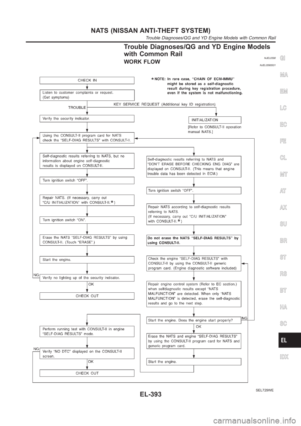
Trouble Diagnoses/QG and YD Engine Models
with Common Rail
NJEL0590WORK FLOWNJEL0590S01
SEL729WE
GI
MA
EM
LC
EC
FE
CL
MT
AT
AX
SU
BR
ST
RS
BT
HA
SC
IDX
NATS (NISSAN ANTI-THEFT SYSTEM)
Trouble Diagnoses/QG and YD Engine Models with Common Rail
EL-393
Page 2730 of 3189
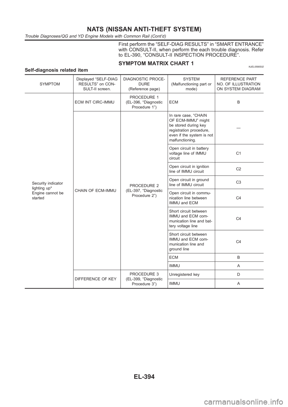
First perform the “SELF-DIAG RESULTS” in “SMART ENTRANCE”
with CONSULT-II, when perform the each trouble diagnosis. Refer
to EL-390, “CONSULT-II INSPECTION PROCEDURE”.
SYMPTOM MATRIX CHART 1NJEL0590S02Self-diagnosis related item
SYMPTOMDisplayed “SELF-DIAG
RESULTS” on CON-
SULT-II screen.DIAGNOSTIC PROCE-
DURE
(Reference page)SYSTEM
(Malfunctioning part or
mode)REFERENCE PART
NO. OF ILLUSTRATION
ON SYSTEM DIAGRAM
Security indicator
lighting up*
Engine cannot be
startedECM INT CIRC-IMMUPROCEDURE 1
(EL-396, “Diagnostic
Procedure 1”)ECM B
CHAIN OF ECM-IMMUPROCEDURE 2
(EL-397, “Diagnostic
Procedure 2”)In rare case, “CHAIN
OF ECM-IMMU” might
be stored during key
registration procedure,
even if the system is not
malfunctioning.—
Open circuit in battery
voltage line of IMMU
circuitC1
Open circuit in ignition
line of IMMU circuitC2
Open circuit in ground
line of IMMU circuitC3
Open circuit in commu-
nication line between
IMMU and ECMC4
Short circuit between
IMMU and ECM com-
munication line and bat-
tery voltage lineC4
Short circuit between
IMMU and ECM com-
munication line and
ground lineC4
ECM B
IMMU A
DIFFERENCE OF KEYPROCEDURE 3
(EL-399, “Diagnostic
Procedure 3”)Unregistered key D
IMMU A
NATS (NISSAN ANTI-THEFT SYSTEM)
Trouble Diagnoses/QG and YD Engine Models with Common Rail (Cont’d)
EL-394