NISSAN ALMERA TINO 2001 Service Repair Manual
Manufacturer: NISSAN, Model Year: 2001, Model line: ALMERA TINO, Model: NISSAN ALMERA TINO 2001Pages: 3051, PDF Size: 46.38 MB
Page 1401 of 3051
SEF552W
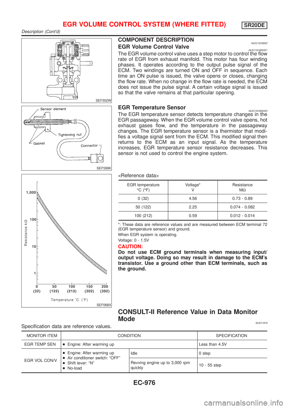
COMPONENT DESCRIPTIONNLEC1818S02EGR Volume Control ValveNLEC1818S0201The EGR volume control valve uses a step motor to control the flow
rate of EGR from exhaust manifold. This motor has four winding
phases. It operates according to the output pulse signal of the
ECM. Two windings are turned ON and OFF in sequence. Each
time an ON pulse is issued, the valve opens or closes, changing
the flow rate. When no change in the flow rate is needed, the ECM
does not issue the pulse signal. A certain voltage signal is issued
so that the valve remains at that particular opening.
SEF599K
EGR Temperature SensorNLEC1818S0203The EGR temperature sensor detects temperature changes in the
EGR passageway. When the EGR volume control valve opens, hot
exhaust gases flow, and the temperature in the passageway
changes. The EGR temperature sensor is a thermistor that modi-
fies a voltage signal sent from the ECM. This modified signal then
returns to the ECM as an input signal. As the temperature
increases, EGR temperature sensor resistance decreases. This
sensor is not used to control the engine system.
SEF068X
EGR temperature
ÉC (ÉF)Voltage*
VResistance
MW
0 (32) 4.56 0.73 - 0.89
50 (122) 2.25 0.074 - 0.082
100 (212) 0.59 0.012 - 0.014
*: These data are reference values and are measured between ECM terminal 72
(EGR temperature sensor) and ground.
When EGR system is operating.
Voltage: 0 - 1.5V
CAUTION:
Do not use ECM ground terminals when measuring input/
output voltage. Doing so may result in damage to the ECM's
transistor. Use a ground other than ECM terminals, such as
the ground.
CONSULT-II Reference Value in Data Monitor
Mode
NLEC1819Specification data are reference values.
MONITOR ITEM CONDITION SPECIFICATION
EGR TEMP SEN+Engine: After warming up Less than 4.5V
EGR VOL CON/V+Engine: After warming up
+Air conditioner switch: ªOFFº
+Shift lever: ªNº
+No-loadIdle 0 step
Revving engine up to 3,000 rpm
quickly10 - 55 step
EGR VOLUME CONTROL SYSTEM (WHERE FITTED)SR20DE
Description (Cont'd)
EC-976
Page 1402 of 3051
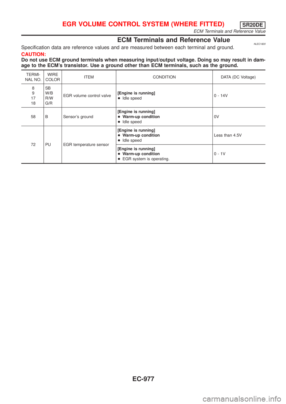
ECM Terminals and Reference ValueNLEC1820Specification data are reference values and are measured between each terminal and ground.
CAUTION:
Do not use ECM ground terminals when measuring input/output voltage. Doing so may result in dam-
age to the ECM's transistor. Use a ground other than ECM terminals, such as the ground.
TERMI-
NAL NO.WIRE
COLORITEM CONDITION DATA (DC Voltage)
8
9
17
18SB
W/B
R/W
G/REGR volume control valve[Engine is running]
+Idle speed0 - 14V
58 B Sensor's ground[Engine is running]
+Warm-up condition
+Idle speed0V
72 PU EGR temperature sensor[Engine is running]
+Warm-up condition
+Idle speedLess than 4.5V
[Engine is running]
+Warm-up condition
+EGR system is operating.0-1V
EGR VOLUME CONTROL SYSTEM (WHERE FITTED)SR20DE
ECM Terminals and Reference Value
EC-977
Page 1403 of 3051
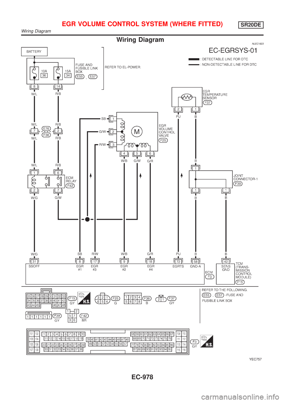
Wiring DiagramNLEC1823
YEC757
EGR VOLUME CONTROL SYSTEM (WHERE FITTED)SR20DE
Wiring Diagram
EC-978
Page 1404 of 3051
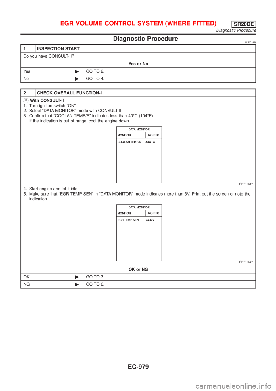
Diagnostic ProcedureNLEC1825
1 INSPECTION START
Do you have CONSULT-II?
YesorNo
Ye s©GO TO 2.
No©GO TO 4.
2 CHECK OVERALL FUNCTION-I
With CONSULT-II
1. Turn ignition switch ªONº.
2. Select ªDATA MONITORº mode with CONSULT-II.
3. Confirm that ªCOOLAN TEMP/Sº indicates less than 40ÉC (104ÉF).
If the indication is out of range, cool the engine down.
SEF013Y
4. Start engine and let it idle.
5. Make sure that ªEGR TEMP SENº in ªDATA MONITORº mode indicates more than 3V. Print out the screen or note the
indication.
SEF014Y
OK or NG
OK©GO TO 3.
NG©GO TO 6.
EGR VOLUME CONTROL SYSTEM (WHERE FITTED)SR20DE
Diagnostic Procedure
EC-979
Page 1405 of 3051
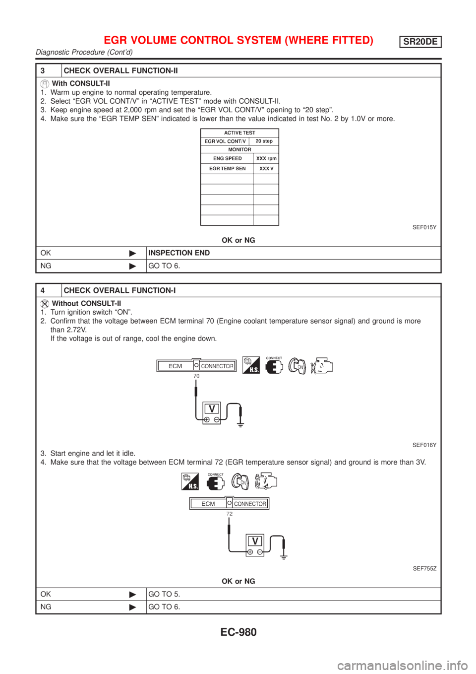
3 CHECK OVERALL FUNCTION-II
With CONSULT-II
1. Warm up engine to normal operating temperature.
2. Select ªEGR VOL CONT/Vº in ªACTIVE TESTº mode with CONSULT-II.
3. Keep engine speed at 2,000 rpm and set the ªEGR VOL CONT/Vº opening to ª20 stepº.
4. Make sure the ªEGR TEMP SENº indicated is lower than the value indicated in test No. 2 by 1.0V or more.
SEF015Y
OK or NG
OK©INSPECTION END
NG©GO TO 6.
4 CHECK OVERALL FUNCTION-I
Without CONSULT-II
1. Turn ignition switch ªONº.
2. Confirm that the voltage between ECM terminal 70 (Engine coolant temperature sensor signal) and ground is more
than 2.72V.
If the voltage is out of range, cool the engine down.
SEF016Y
3. Start engine and let it idle.
4. Make sure that the voltage between ECM terminal 72 (EGR temperature sensor signal) and ground is more than 3V.
SEF755Z
OK or NG
OK©GO TO 5.
NG©GO TO 6.
EGR VOLUME CONTROL SYSTEM (WHERE FITTED)SR20DE
Diagnostic Procedure (Cont'd)
EC-980
Page 1406 of 3051
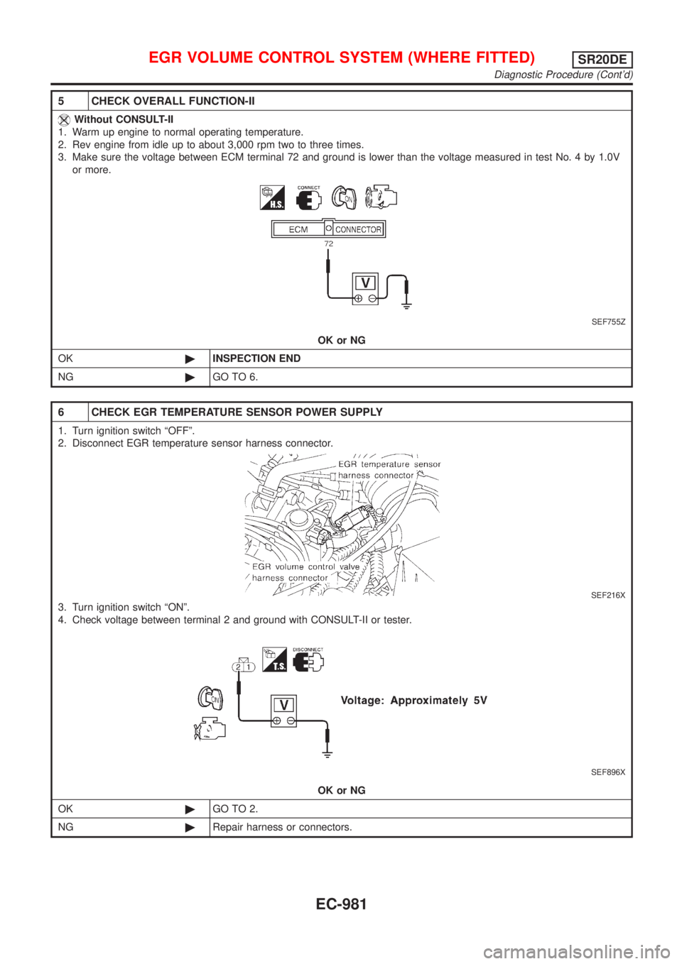
5 CHECK OVERALL FUNCTION-II
Without CONSULT-II
1. Warm up engine to normal operating temperature.
2. Rev engine from idle up to about 3,000 rpm two to three times.
3. Make sure the voltage between ECM terminal 72 and ground is lower than the voltage measured in test No. 4 by 1.0V
or more.
SEF755Z
OK or NG
OK©INSPECTION END
NG©GO TO 6.
6 CHECK EGR TEMPERATURE SENSOR POWER SUPPLY
1. Turn ignition switch ªOFFº.
2. Disconnect EGR temperature sensor harness connector.
SEF216X
3. Turn ignition switch ªONº.
4. Check voltage between terminal 2 and ground with CONSULT-II or tester.
SEF896X
OK or NG
OK©GO TO 2.
NG©Repair harness or connectors.
EGR VOLUME CONTROL SYSTEM (WHERE FITTED)SR20DE
Diagnostic Procedure (Cont'd)
EC-981
Page 1407 of 3051
7 CHECK GROUND CIRCUIT
1. Turn ignition switch ªOFFº.
2. Check harness continuity between EGR temperature sensor harness terminal 1 and engine ground.
Refer to wiring diagram.
Continuity should exist.
3. Also check harness for short to power.
OK or NG
OK©GO TO 9.
NG©GO TO 8.
8 DETECT MALFUNCTIONING PART
Check the following.
+Joint connector-1
+Harness for open or short between EGR temperature sensor and ECM
+Harness for open or short between EGR temperature sensor and TCM
©Repair open circuit or short to power in harness or connector.
9 CHECK EGR TEMPERATURE SENSOR
Refer to ªComponent Inspectionº, EC-985.
OK or NG
OK©GO TO 10.
NG©Replace EGR temperature senosr.
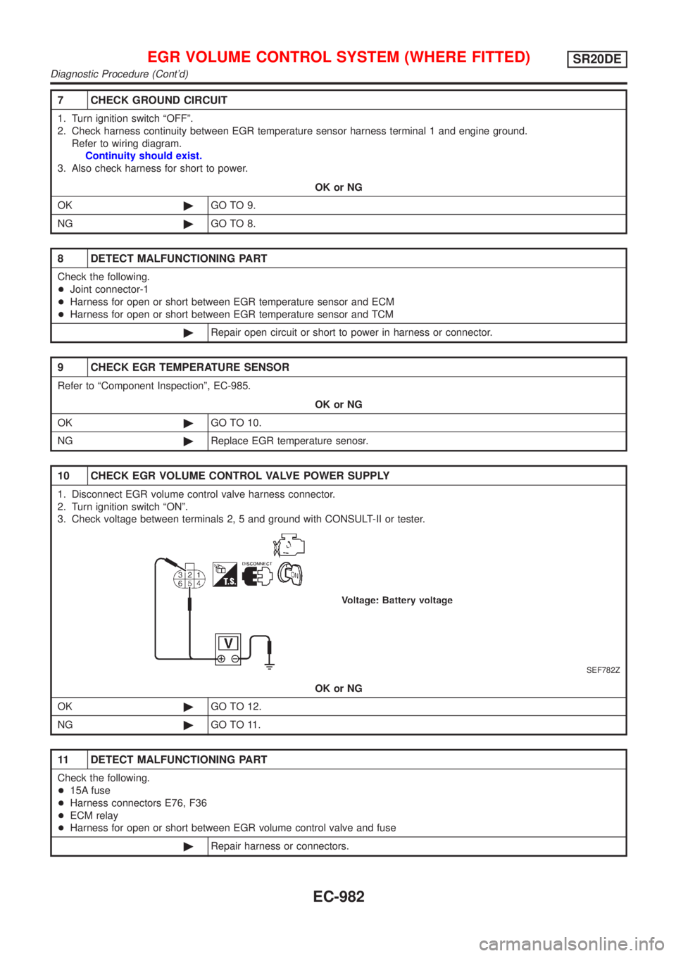
10 CHECK EGR VOLUME CONTROL VALVE POWER SUPPLY
1. Disconnect EGR volume control valve harness connector.
2. Turn ignition switch ªONº.
3. Check voltage between terminals 2, 5 and ground with CONSULT-II or tester.
SEF782Z
OK or NG
OK©GO TO 12.
NG©GO TO 11.
11 DETECT MALFUNCTIONING PART
Check the following.
+15A fuse
+Harness connectors E76, F36
+ECM relay
+Harness for open or short between EGR volume control valve and fuse
©Repair harness or connectors.
EGR VOLUME CONTROL SYSTEM (WHERE FITTED)SR20DE
Diagnostic Procedure (Cont'd)
EC-982
Page 1408 of 3051
12 CHECK EGR VOLUME CONTROL VALAVE OUTPUT SIGNAL CIRCUIT
1. Turn ignition switch ªOFFº.
2. Disconnect ECM harness connector.
3. Check harness continuity between
ECM terminal 8 and EGR volume control valve terminal 1,
ECM terminal 9 and EGR volume control valve terminal 4,
ECM terminal 17 and EGR volume control valve terminal 3,
ECM terminal 18 and EGR volume control valve terminal 6.
Refer to wiring diagram.
Continuity should exist.
4. Also check harness for short to ground and short to power.
OK or NG
OK©GO TO 13.
NG©Repair open circuit, short to ground or short to power in harness connectors.
13 CHECK EGR PASSAGE
Check EGR passage for clogging and cracks.
OK or NG
OK©GO TO 14.
NG©Repair or replace EGR passage.
14 CHECK EGR VOLUME CONTROL VALVE
Refer to ªCOMPONENT INSPECTIONº, EC-984.
OK or NG
OK©GO TO 15.
NG©Replace EGR volume control valve.
15 CHECK INTERMITTENT INCIDENT
Perform ªTROUBLE DIAGNOSIS FOR INTERMITTENT INCIDENTº, EC-670.
©INSPECTION END
EGR VOLUME CONTROL SYSTEM (WHERE FITTED)SR20DE
Diagnostic Procedure (Cont'd)
EC-983
Page 1409 of 3051
SEF216X
SEF783Z
SEF015Y
SEF560W
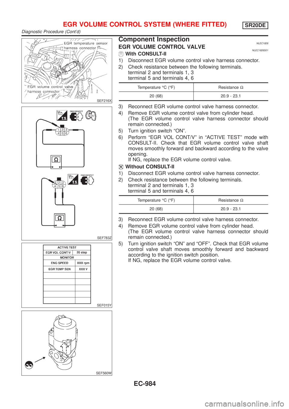
Component InspectionNLEC1826EGR VOLUME CONTROL VALVENLEC1826S01With CONSULT-II
1) Disconnect EGR volume control valve harness connector.
2) Check resistance between the following terminals.
terminal 2 and terminals 1, 3
terminal 5 and terminals 4, 6
Temperature ÉC (ÉF) ResistanceW
20 (68) 20.9 - 23.1
3) Reconnect EGR volume control valve harness connector.
4) Remove EGR volume control valve from cylinder head.
(The EGR volume control valve harness connector should
remain connected.)
5) Turn ignition switch ªONº.
6) Perform ªEGR VOL CONT/Vº in ªACTIVE TESTº mode with
CONSULT-II. Check that EGR volume control valve shaft
moves smoothly forward and backward according to the valve
opening.
If NG, replace the EGR volume control valve.
Without CONSULT-II
1) Disconnect EGR volume control valve harness connector.
2) Check resistance between the following terminals.
terminal 2 and terminals 1, 3
terminal 5 and terminals 4, 6
Temperature ÉC (ÉF) ResistanceW
20 (68) 20.9 - 23.1
3) Reconnect EGR volume control valve harness connector.
4) Remove EGR volume control valve from cylinder head.
(The EGR volume control valve harness connector should
remain connected.)
5) Turn ignition switch ªONº and ªOFFº. Check that EGR volume
control valve shaft moves smoothly forward and backward
according to the ignition switch position.
If NG, replace the EGR volume control valve.
EGR VOLUME CONTROL SYSTEM (WHERE FITTED)SR20DE
Diagnostic Procedure (Cont'd)
EC-984
Page 1410 of 3051
SEF611Y
SEF068X
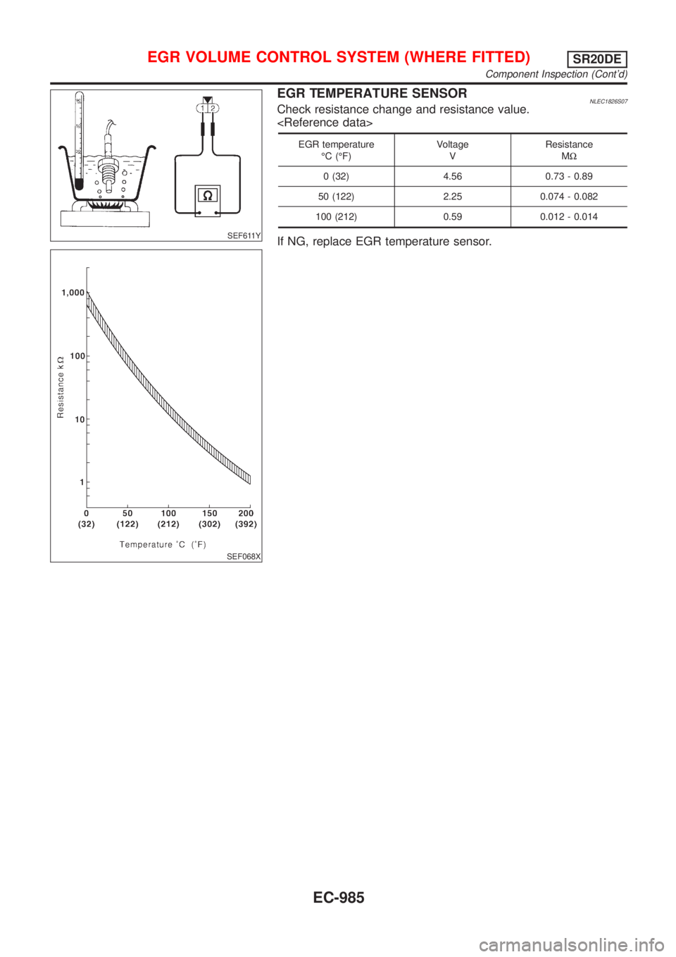
EGR TEMPERATURE SENSORNLEC1826S07Check resistance change and resistance value.
EGR temperature
ÉC (ÉF)Voltage
VResistance
MW
0 (32) 4.56 0.73 - 0.89
50 (122) 2.25 0.074 - 0.082
100 (212) 0.59 0.012 - 0.014
If NG, replace EGR temperature sensor.
EGR VOLUME CONTROL SYSTEM (WHERE FITTED)SR20DE
Component Inspection (Cont'd)
EC-985