NISSAN ALMERA TINO 2001 Service Repair Manual
Manufacturer: NISSAN, Model Year: 2001, Model line: ALMERA TINO, Model: NISSAN ALMERA TINO 2001Pages: 3051, PDF Size: 46.38 MB
Page 1381 of 3051
SEF327R
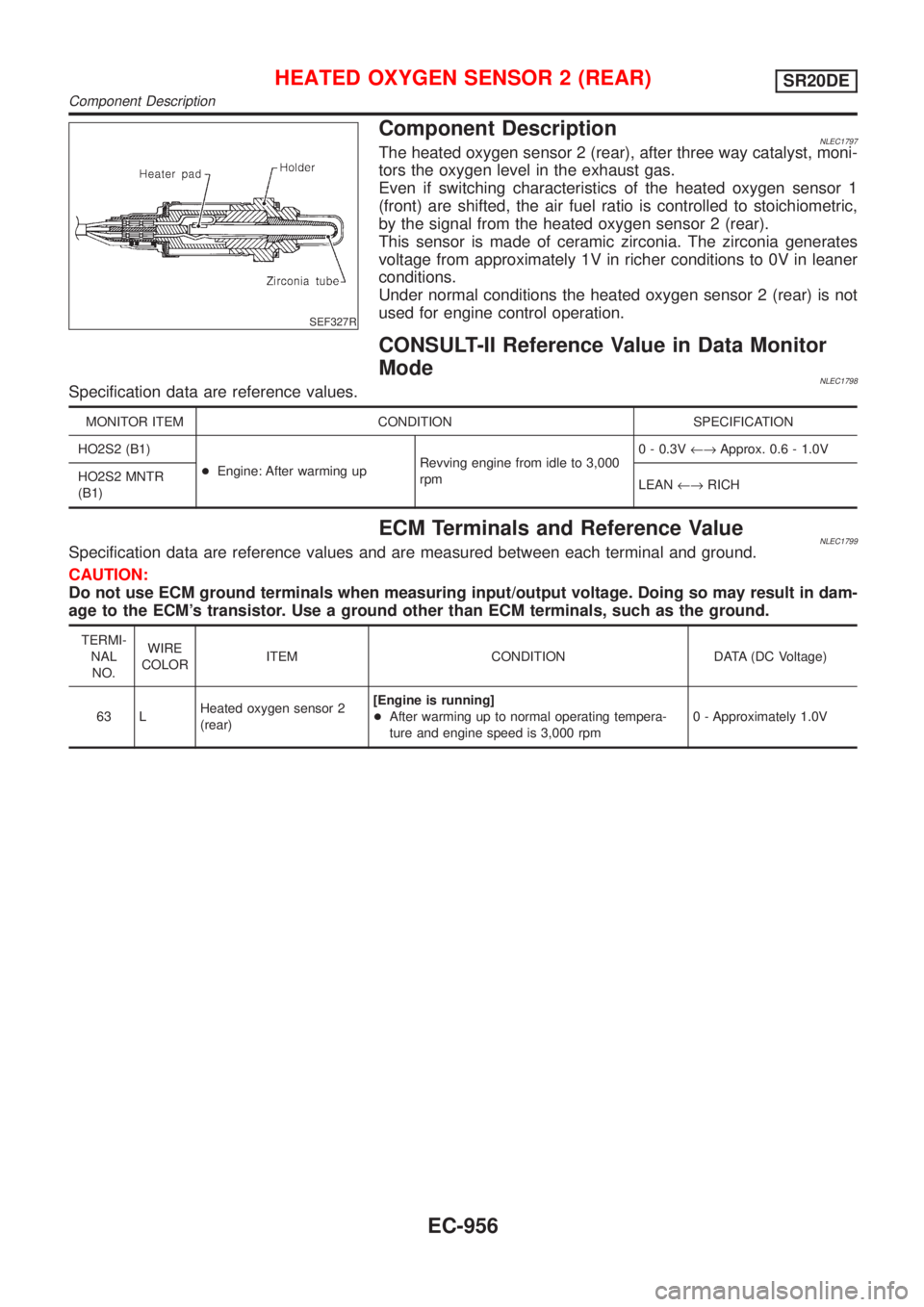
Component DescriptionNLEC1797The heated oxygen sensor 2 (rear), after three way catalyst, moni-
tors the oxygen level in the exhaust gas.
Even if switching characteristics of the heated oxygen sensor 1
(front) are shifted, the air fuel ratio is controlled to stoichiometric,
by the signal from the heated oxygen sensor 2 (rear).
This sensor is made of ceramic zirconia. The zirconia generates
voltage from approximately 1V in richer conditions to 0V in leaner
conditions.
Under normal conditions the heated oxygen sensor 2 (rear) is not
used for engine control operation.
CONSULT-II Reference Value in Data Monitor
Mode
NLEC1798Specification data are reference values.
MONITOR ITEM CONDITION SPECIFICATION
HO2S2 (B1)
+Engine: After warming upRevving engine from idle to 3,000
rpm0 - 0.3V¨Approx. 0.6 - 1.0V
HO2S2 MNTR
(B1)LEAN¨RICH
ECM Terminals and Reference ValueNLEC1799Specification data are reference values and are measured between each terminal and ground.
CAUTION:
Do not use ECM ground terminals when measuring input/output voltage. Doing so may result in dam-
age to the ECM's transistor. Use a ground other than ECM terminals, such as the ground.
TERMI-
NAL
NO.WIRE
COLORITEM CONDITION DATA (DC Voltage)
63 LHeated oxygen sensor 2
(rear)[Engine is running]
+After warming up to normal operating tempera-
ture and engine speed is 3,000 rpm0 - Approximately 1.0V
HEATED OXYGEN SENSOR 2 (REAR)SR20DE
Component Description
EC-956
Page 1382 of 3051
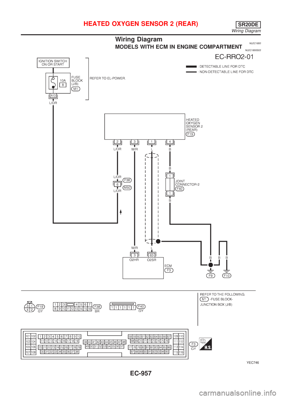
Wiring DiagramNLEC1800MODELS WITH ECM IN ENGINE COMPARTMENTNLEC1800S03
YEC746
HEATED OXYGEN SENSOR 2 (REAR)SR20DE
Wiring Diagram
EC-957
Page 1383 of 3051
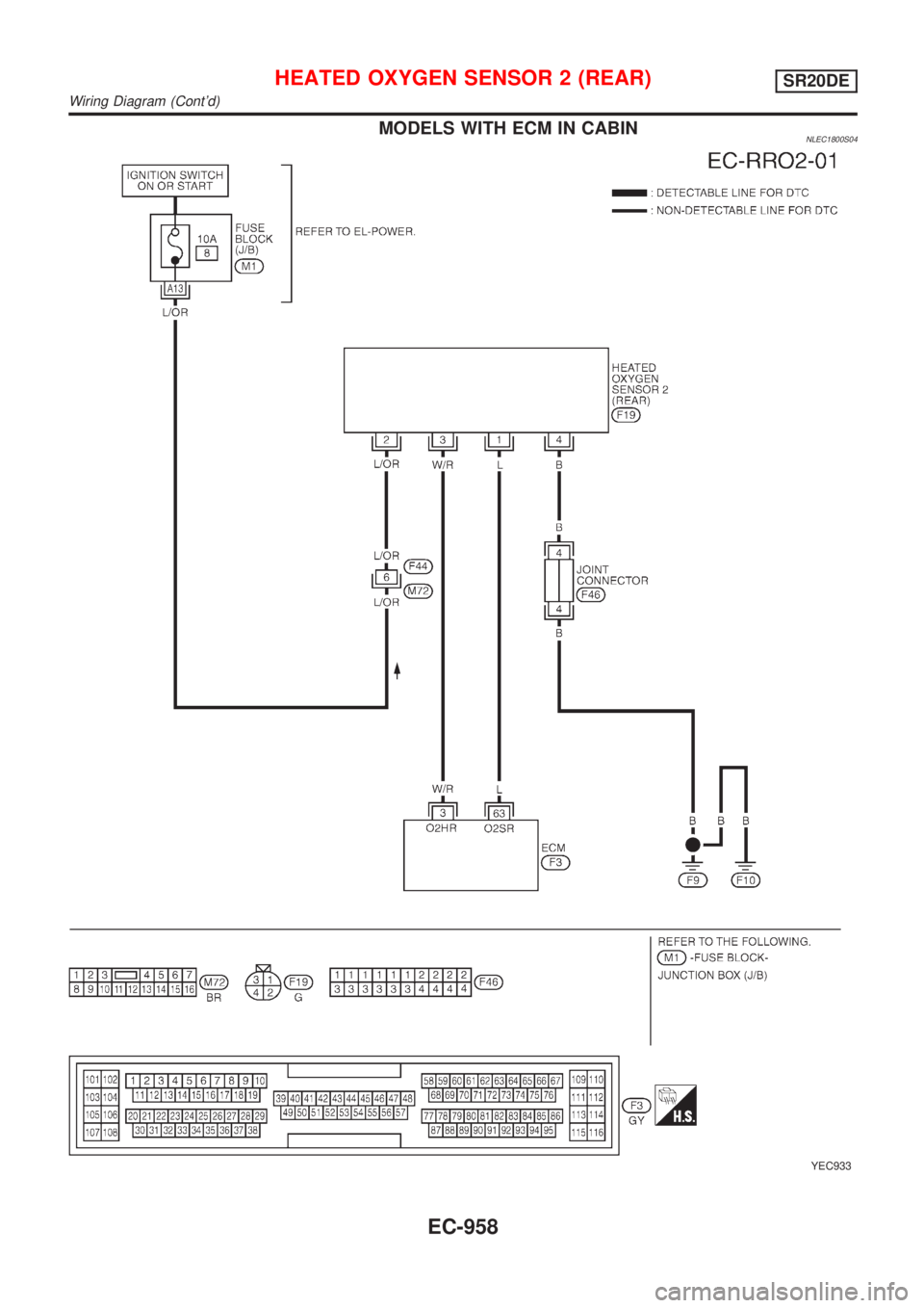
MODELS WITH ECM IN CABINNLEC1800S04
YEC933
HEATED OXYGEN SENSOR 2 (REAR)SR20DE
Wiring Diagram (Cont'd)
EC-958
Page 1384 of 3051
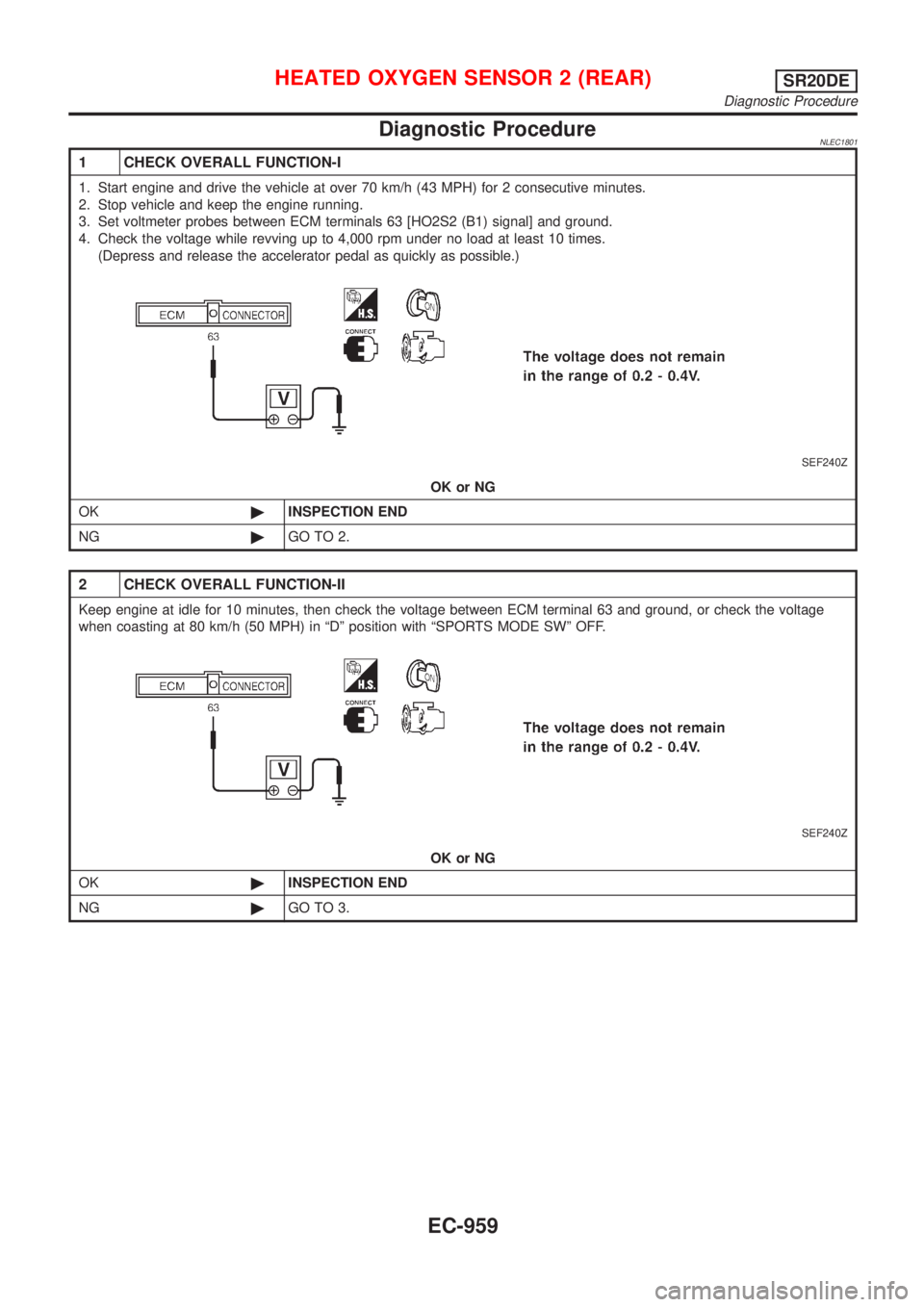
Diagnostic ProcedureNLEC1801
1 CHECK OVERALL FUNCTION-I
1. Start engine and drive the vehicle at over 70 km/h (43 MPH) for 2 consecutive minutes.
2. Stop vehicle and keep the engine running.
3. Set voltmeter probes between ECM terminals 63 [HO2S2 (B1) signal] and ground.
4. Check the voltage while revving up to 4,000 rpm under no load at least 10 times.
(Depress and release the accelerator pedal as quickly as possible.)
SEF240Z
OK or NG
OK©INSPECTION END
NG©GO TO 2.
2 CHECK OVERALL FUNCTION-II
Keep engine at idle for 10 minutes, then check the voltage between ECM terminal 63 and ground, or check the voltage
when coasting at 80 km/h (50 MPH) in ªDº position with ªSPORTS MODE SWº OFF.
SEF240Z
OK or NG
OK©INSPECTION END
NG©GO TO 3.
HEATED OXYGEN SENSOR 2 (REAR)SR20DE
Diagnostic Procedure
EC-959
Page 1385 of 3051
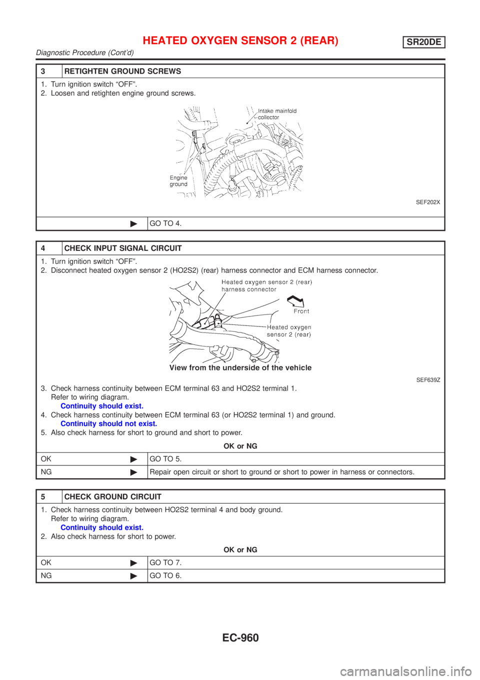
3 RETIGHTEN GROUND SCREWS
1. Turn ignition switch ªOFFº.
2. Loosen and retighten engine ground screws.
SEF202X
©GO TO 4.
4 CHECK INPUT SIGNAL CIRCUIT
1. Turn ignition switch ªOFFº.
2. Disconnect heated oxygen sensor 2 (HO2S2) (rear) harness connector and ECM harness connector.
SEF639Z
3. Check harness continuity between ECM terminal 63 and HO2S2 terminal 1.
Refer to wiring diagram.
Continuity should exist.
4. Check harness continuity between ECM terminal 63 (or HO2S2 terminal 1) and ground.
Continuity should not exist.
5. Also check harness for short to ground and short to power.
OK or NG
OK©GO TO 5.
NG©Repair open circuit or short to ground or short to power in harness or connectors.
5 CHECK GROUND CIRCUIT
1. Check harness continuity between HO2S2 terminal 4 and body ground.
Refer to wiring diagram.
Continuity should exist.
2. Also check harness for short to power.
OK or NG
OK©GO TO 7.
NG©GO TO 6.
HEATED OXYGEN SENSOR 2 (REAR)SR20DE
Diagnostic Procedure (Cont'd)
EC-960
Page 1386 of 3051
6 DETECT MALFUNCTIONING PART
Check the following.
+Joint connector-2 (where fitted)
+Joint connector F46 (where fitted)
+Harness for open or short between HO2S2 and ECM
©Repair open circuit or short to power in harness or connectors.
7 CHECK HEATED OXYGEN SENSOR 2 (REAR)
Refer to ªComponent Inspectionº, EC-961.
OK or NG
OK©GO TO 8.
NG©Replace heated oxygen sensor 2 (rear).
8 CHECK INTERMITTENT INCIDENT
Perform ªTROUBLE DIAGNOSIS FOR INTERMITTENT INCIDENTº, EC-670.
©INSPECTION END
SEF662Y
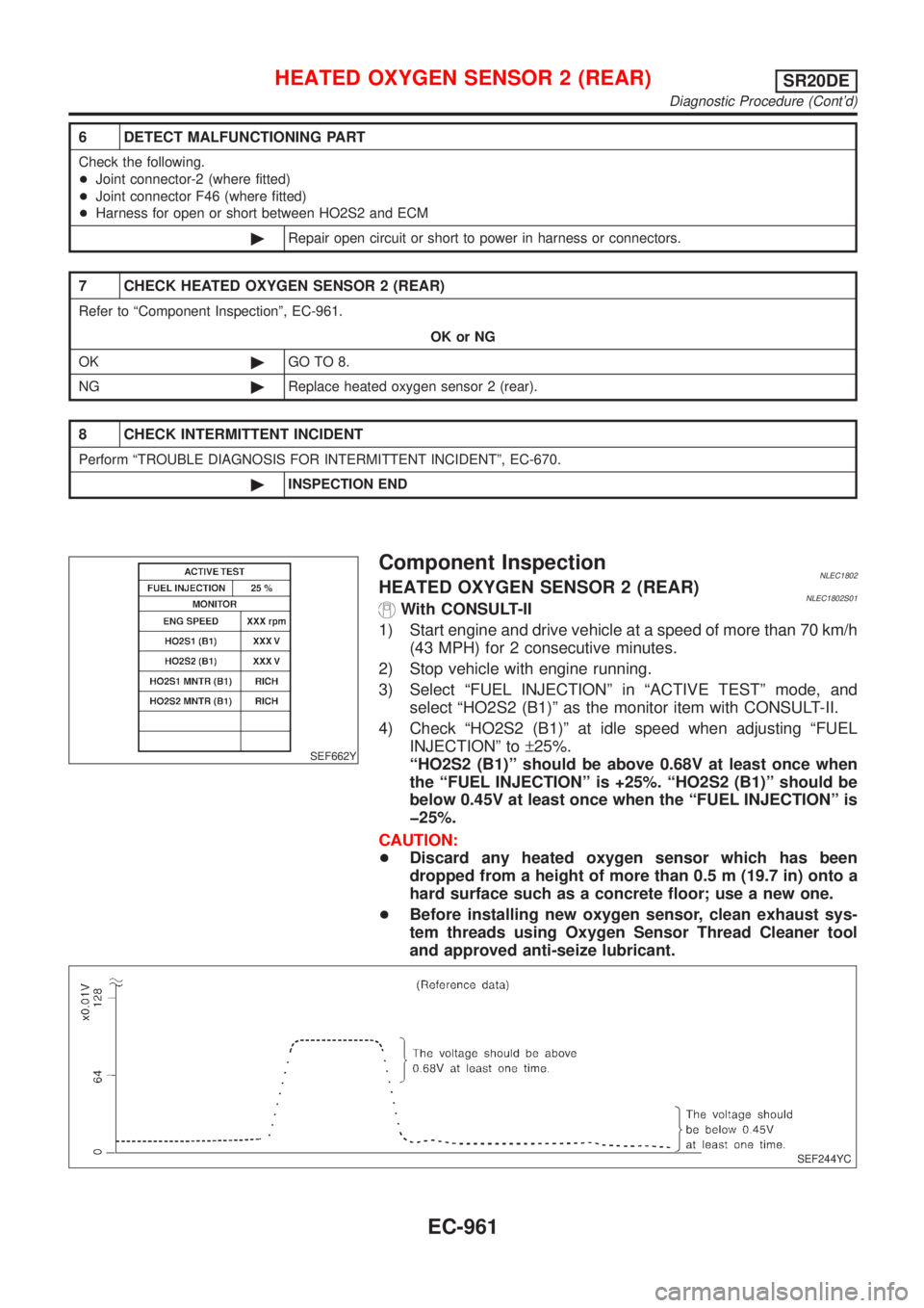
Component InspectionNLEC1802HEATED OXYGEN SENSOR 2 (REAR)NLEC1802S01With CONSULT-II
1) Start engine and drive vehicle at a speed of more than 70 km/h
(43 MPH) for 2 consecutive minutes.
2) Stop vehicle with engine running.
3) Select ªFUEL INJECTIONº in ªACTIVE TESTº mode, and
select ªHO2S2 (B1)º as the monitor item with CONSULT-II.
4) Check ªHO2S2 (B1)º at idle speed when adjusting ªFUEL
INJECTIONº to±25%.
ªHO2S2 (B1)º should be above 0.68V at least once when
the ªFUEL INJECTIONº is +25%. ªHO2S2 (B1)º should be
below 0.45V at least once when the ªFUEL INJECTIONº is
þ25%.
CAUTION:
+Discard any heated oxygen sensor which has been
dropped from a height of more than 0.5 m (19.7 in) onto a
hard surface such as a concrete floor; use a new one.
+Before installing new oxygen sensor, clean exhaust sys-
tem threads using Oxygen Sensor Thread Cleaner tool
and approved anti-seize lubricant.
SEF244YC
HEATED OXYGEN SENSOR 2 (REAR)SR20DE
Diagnostic Procedure (Cont'd)
EC-961
Page 1387 of 3051
SEF032X
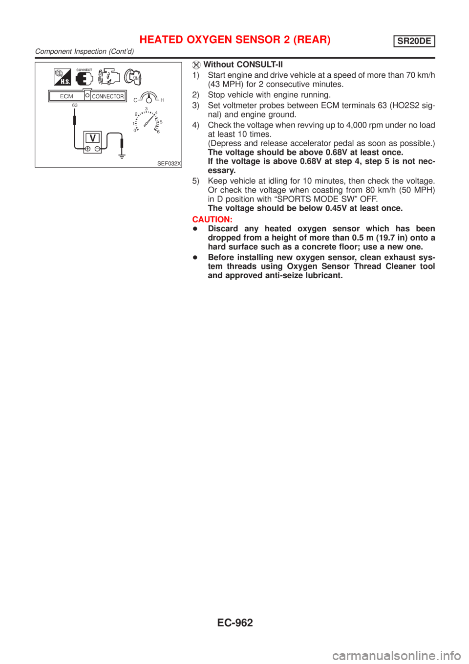
Without CONSULT-II
1) Start engine and drive vehicle at a speed of more than 70 km/h
(43 MPH) for 2 consecutive minutes.
2) Stop vehicle with engine running.
3) Set voltmeter probes between ECM terminals 63 (HO2S2 sig-
nal) and engine ground.
4) Check the voltage when revving up to 4,000 rpm under no load
at least 10 times.
(Depress and release accelerator pedal as soon as possible.)
The voltage should be above 0.68V at least once.
If the voltage is above 0.68V at step 4, step 5 is not nec-
essary.
5) Keep vehicle at idling for 10 minutes, then check the voltage.
Or check the voltage when coasting from 80 km/h (50 MPH)
in D position with ªSPORTS MODE SWº OFF.
The voltage should be below 0.45V at least once.
CAUTION:
+Discard any heated oxygen sensor which has been
dropped from a height of more than 0.5 m (19.7 in) onto a
hard surface such as a concrete floor; use a new one.
+Before installing new oxygen sensor, clean exhaust sys-
tem threads using Oxygen Sensor Thread Cleaner tool
and approved anti-seize lubricant.
HEATED OXYGEN SENSOR 2 (REAR)SR20DE
Component Inspection (Cont'd)
EC-962
Page 1388 of 3051
DescriptionNLEC1803SYSTEM DESCRIPTIONNLEC1803S01
Sensor Input Signal to ECM ECM function Actuator
Camshaft position sensor Engine speedHeated oxygen sensor
2 heater (rear) controlHeated oxygen sensor 2 heater
(rear)
The ECM performs ON/OFF control of the heated oxygen sensor 2 heater (rear) corresponding to the engine
speed.
OPERATIONNLEC1803S02
Engine condition Heated oxygen sensor 2 heater (rear)
Engine stopped OFF
Engine is running. Engine speed below 3,600 rpm
After driving for 2 minutes at a speed
of 70 km/h (43 MPH) or moreON
Engine speed above 3,600 rpm OFF
CONSULT-II Reference Value in Data Monitor
Mode
NLEC1804Specification data are reference values.
MONITOR ITEM CONDITION SPECIFICATION
HO2S2 HTR (B1)+Engine speedBelow 3,600 rpm [After driving for 2 minutes at a
speed of 70 km/h (43 MPH) or more]ON
Above 3,600 rpm OFF
+Ignition switch ON (Engine stopped) OFF
ECM Terminals and Reference ValueNLEC1805Specification data are reference values and are measured between each terminal and ground.
CAUTION:
Do not use ECM ground terminals when measuring input/output voltage. Doing so may result in dam-
age to the ECM's transistor. Use a ground other than ECM terminals, such as the ground.
TERMI-
NAL
NO.WIRE
COLORITEM CONDITION DATA (DC Voltage)
3 W/RHeated oxygen sensor 2
heater (rear)[Engine is running]
+Engine speed is below 3,600 rpm [After driving
for 2 minutes at a speed of 70 km/h (43 MPH) or
more]0-1V
[Engine is running]
+Engine speed is above 3,600 rpm
BATTERY VOLTAGE
(11 - 14V)
[Ignition switch ªONº]
+Engine stopped
HEATED OXYGEN SENSOR 2 HEATER (REAR)SR20DE
Description
EC-963
Page 1389 of 3051
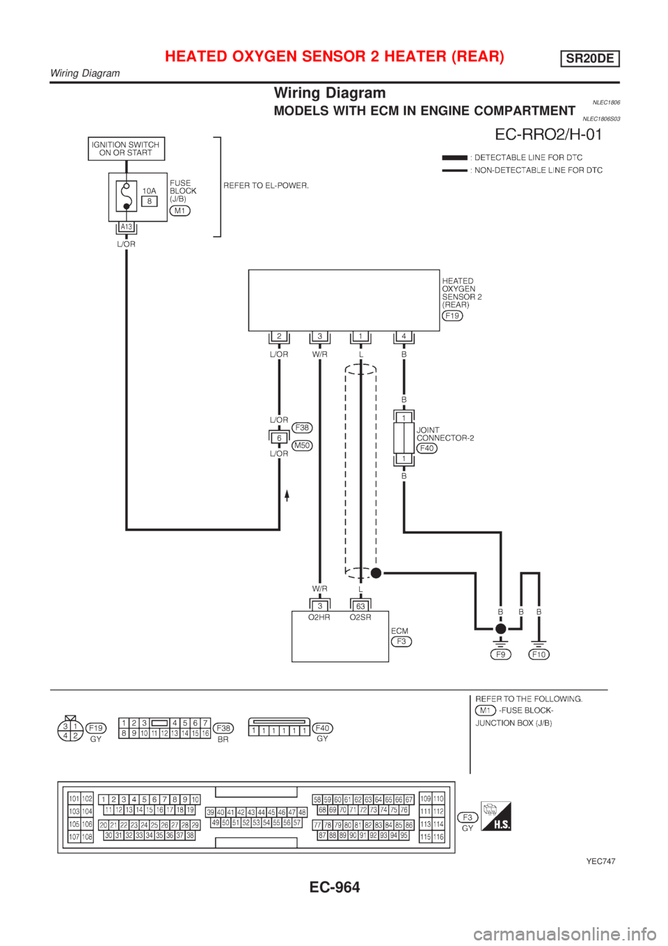
Wiring DiagramNLEC1806MODELS WITH ECM IN ENGINE COMPARTMENTNLEC1806S03
YEC747
HEATED OXYGEN SENSOR 2 HEATER (REAR)SR20DE
Wiring Diagram
EC-964
Page 1390 of 3051
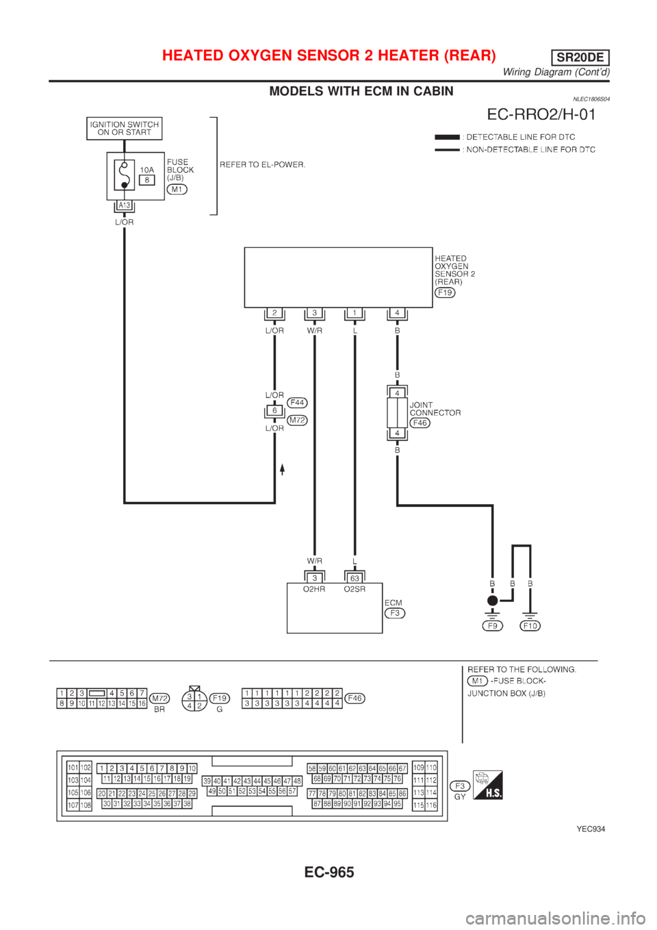
MODELS WITH ECM IN CABINNLEC1806S04
YEC934
HEATED OXYGEN SENSOR 2 HEATER (REAR)SR20DE
Wiring Diagram (Cont'd)
EC-965