NISSAN ALMERA TINO 2001 Service Repair Manual
ALMERA TINO 2001
NISSAN
NISSAN
https://www.carmanualsonline.info/img/5/57352/w960_57352-0.png
NISSAN ALMERA TINO 2001 Service Repair Manual
Trending: transmission, compression ratio, gas mileage, wheel size, suspension, display, engine
Page 1361 of 3051
6 CHECK INTERMITTENT INCIDENT
Perform ªTROUBLE DIAGNOSIS FOR INTERMITTENT INCIDENTº, EC-670.
©INSPECTION END
DTC P1706 PARK/NEUTRAL POSITION (PNP) SWITCHSR20DE
Diagnostic Procedure (Cont'd)
EC-936
Page 1362 of 3051
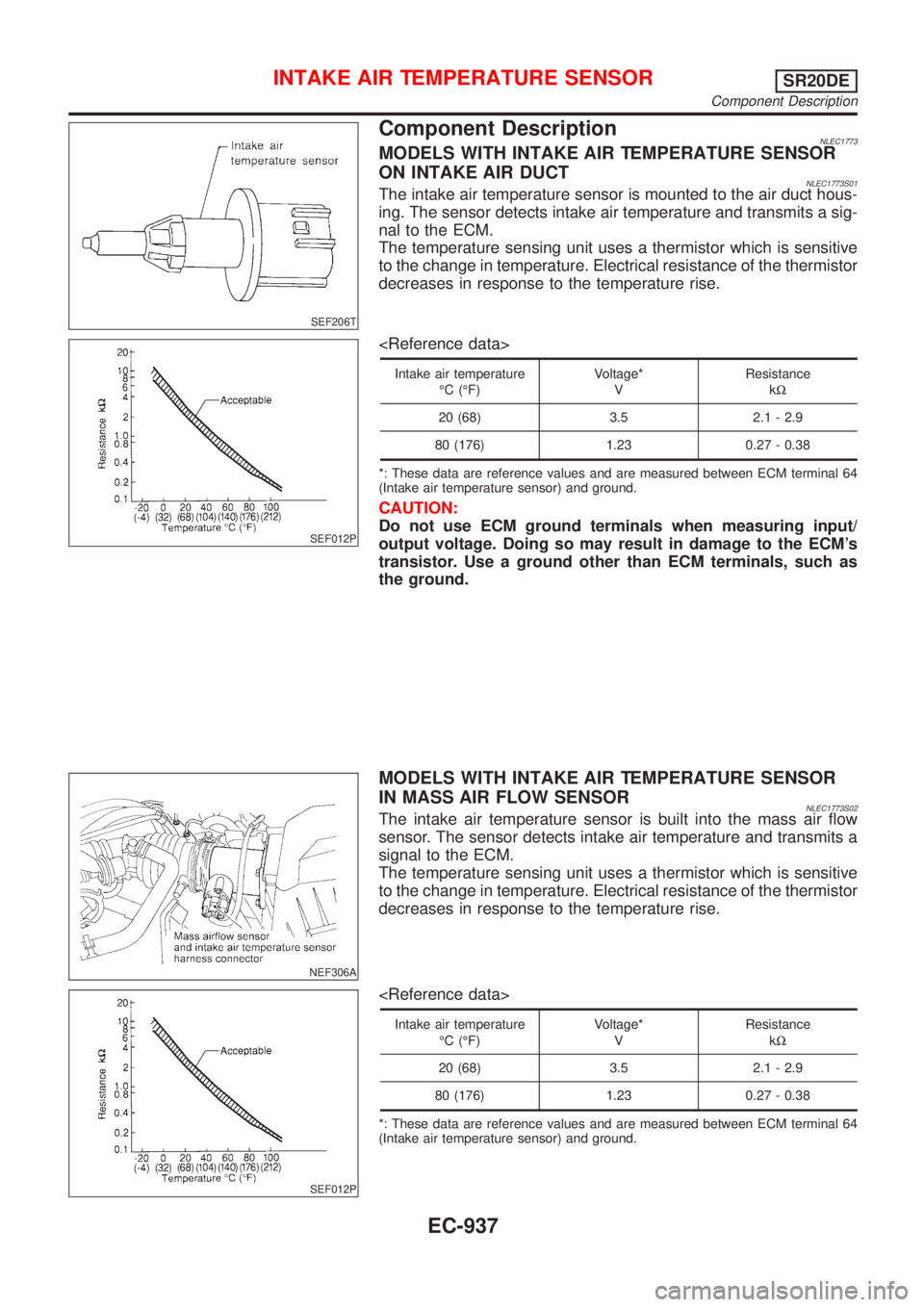
SEF206T
Component DescriptionNLEC1773MODELS WITH INTAKE AIR TEMPERATURE SENSOR
ON INTAKE AIR DUCT
NLEC1773S01The intake air temperature sensor is mounted to the air duct hous-
ing. The sensor detects intake air temperature and transmits a sig-
nal to the ECM.
The temperature sensing unit uses a thermistor which is sensitive
to the change in temperature. Electrical resistance of the thermistor
decreases in response to the temperature rise.
SEF012P
Intake air temperature
ÉC (ÉF)Voltage*
VResistance
kW
20 (68) 3.5 2.1 - 2.9
80 (176) 1.23 0.27 - 0.38
*: These data are reference values and are measured between ECM terminal 64
(Intake air temperature sensor) and ground.
CAUTION:
Do not use ECM ground terminals when measuring input/
output voltage. Doing so may result in damage to the ECM's
transistor. Use a ground other than ECM terminals, such as
the ground.
NEF306A
MODELS WITH INTAKE AIR TEMPERATURE SENSOR
IN MASS AIR FLOW SENSOR
NLEC1773S02The intake air temperature sensor is built into the mass air flow
sensor. The sensor detects intake air temperature and transmits a
signal to the ECM.
The temperature sensing unit uses a thermistor which is sensitive
to the change in temperature. Electrical resistance of the thermistor
decreases in response to the temperature rise.
SEF012P
Intake air temperature
ÉC (ÉF)Voltage*
VResistance
kW
20 (68) 3.5 2.1 - 2.9
80 (176) 1.23 0.27 - 0.38
*: These data are reference values and are measured between ECM terminal 64
(Intake air temperature sensor) and ground.
INTAKE AIR TEMPERATURE SENSORSR20DE
Component Description
EC-937
Page 1363 of 3051
CAUTION:
Do not use ECM ground terminals when measuring input/
output voltage. Doing so may result in damage to the ECM's
transistor. Use a ground other than ECM terminals, such as
the ground.
INTAKE AIR TEMPERATURE SENSORSR20DE
Component Description (Cont'd)
EC-938
Page 1364 of 3051
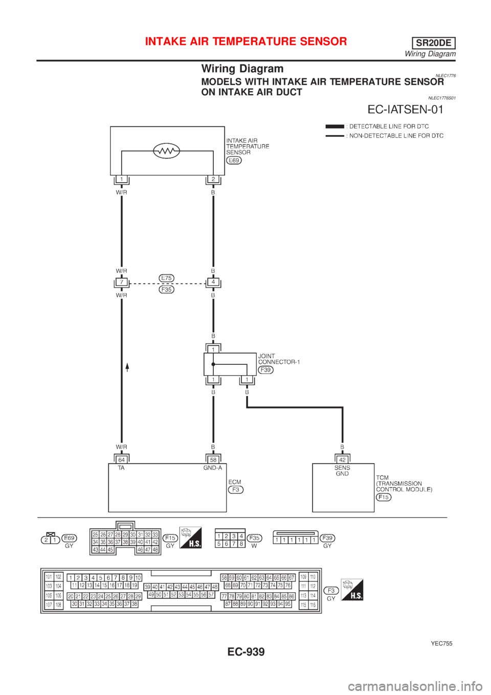
Wiring DiagramNLEC1776MODELS WITH INTAKE AIR TEMPERATURE SENSOR
ON INTAKE AIR DUCT
NLEC1776S01
YEC755
INTAKE AIR TEMPERATURE SENSORSR20DE
Wiring Diagram
EC-939
Page 1365 of 3051
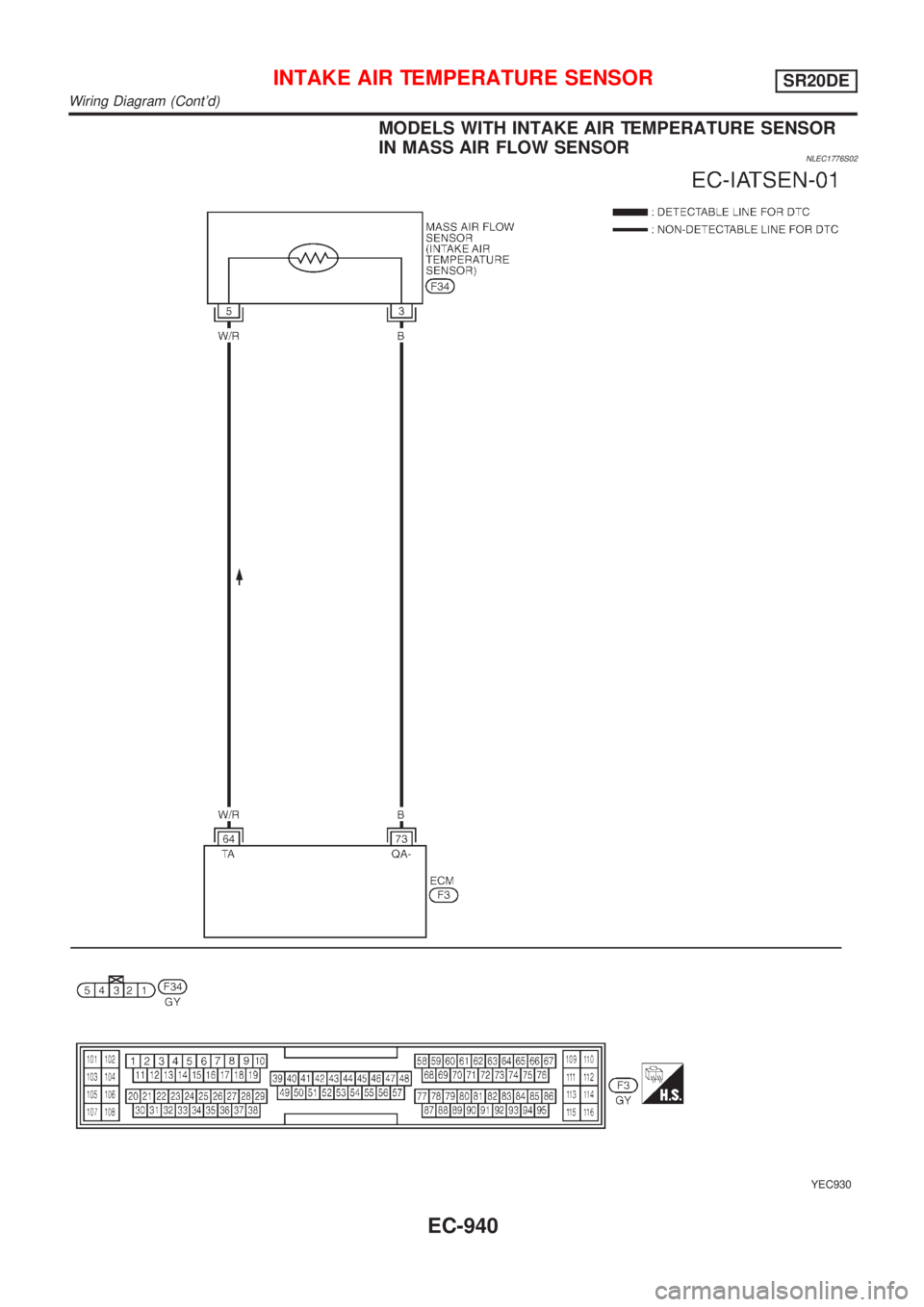
MODELS WITH INTAKE AIR TEMPERATURE SENSOR
IN MASS AIR FLOW SENSOR
NLEC1776S02
YEC930
INTAKE AIR TEMPERATURE SENSORSR20DE
Wiring Diagram (Cont'd)
EC-940
Page 1366 of 3051
Diagnostic ProcedureNLEC1779
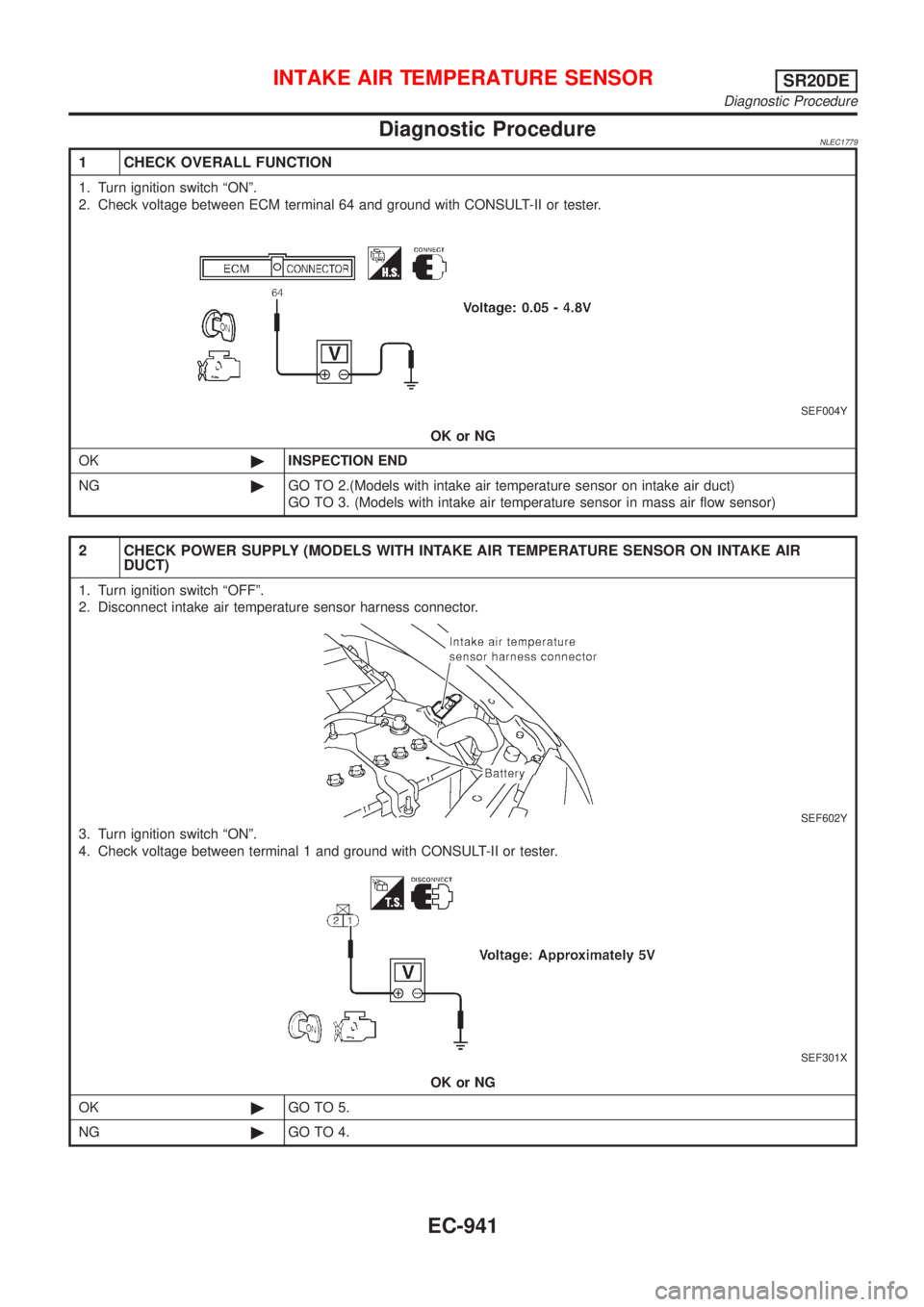
1 CHECK OVERALL FUNCTION
1. Turn ignition switch ªONº.
2. Check voltage between ECM terminal 64 and ground with CONSULT-II or tester.
SEF004Y
OK or NG
OK©INSPECTION END
NG©GO TO 2.(Models with intake air temperature sensor on intake air duct)
GO TO 3. (Models with intake air temperature sensor in mass air flow sensor)
2 CHECK POWER SUPPLY (MODELS WITH INTAKE AIR TEMPERATURE SENSOR ON INTAKE AIR
DUCT)
1. Turn ignition switch ªOFFº.
2. Disconnect intake air temperature sensor harness connector.
SEF602Y
3. Turn ignition switch ªONº.
4. Check voltage between terminal 1 and ground with CONSULT-II or tester.
SEF301X
OK or NG
OK©GO TO 5.
NG©GO TO 4.
INTAKE AIR TEMPERATURE SENSORSR20DE
Diagnostic Procedure
EC-941
Page 1367 of 3051
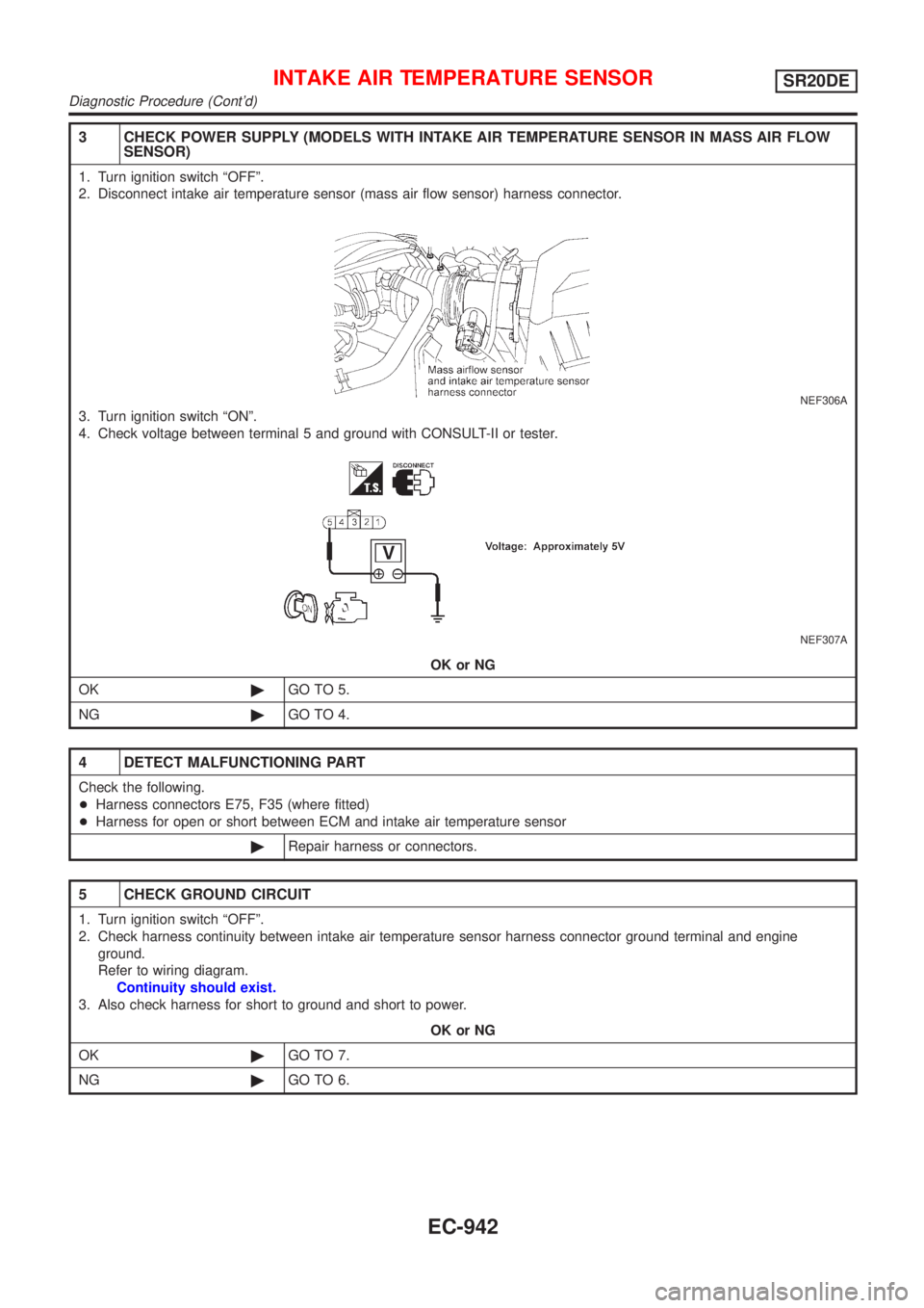
3 CHECK POWER SUPPLY (MODELS WITH INTAKE AIR TEMPERATURE SENSOR IN MASS AIR FLOW
SENSOR)
1. Turn ignition switch ªOFFº.
2. Disconnect intake air temperature sensor (mass air flow sensor) harness connector.
NEF306A
3. Turn ignition switch ªONº.
4. Check voltage between terminal 5 and ground with CONSULT-II or tester.
NEF307A
OK or NG
OK©GO TO 5.
NG©GO TO 4.
4 DETECT MALFUNCTIONING PART
Check the following.
+Harness connectors E75, F35 (where fitted)
+Harness for open or short between ECM and intake air temperature sensor
©Repair harness or connectors.
5 CHECK GROUND CIRCUIT
1. Turn ignition switch ªOFFº.
2. Check harness continuity between intake air temperature sensor harness connector ground terminal and engine
ground.
Refer to wiring diagram.
Continuity should exist.
3. Also check harness for short to ground and short to power.
OK or NG
OK©GO TO 7.
NG©GO TO 6.
INTAKE AIR TEMPERATURE SENSORSR20DE
Diagnostic Procedure (Cont'd)
EC-942
Page 1368 of 3051
6 DETECT MALFUNCTIONING PART
Check the following.
+Joint connector-1 (where fitted)
+Harness connectors E75, F35 (where fitted)
+Harness for open or short between ECM and intake air temperature sensor
+Harness for open or short between TCM (Transmission Control Module) and intake air temperature sensor (where fit-
ted)
©Repair open circuit or short to ground or short to power in harness or connectors.
7 CHECK INTAKE AIR TEMPERATURE SENSOR
Refer to ªComponent Inspectionº, EC-943.
OK or NG
OK©GO TO 8.
NG©Replace intake air temperature sensor.
8 CHECK INTERMITTENT INCIDENT
Perform ªTROUBLE DIAGNOSIS FOR INTERMITTENT INCIDENTº, EC-670.
©INSPECTION END
SEF913W
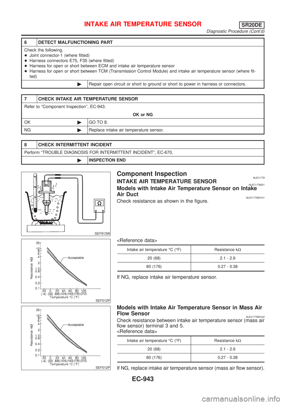
Component InspectionNLEC1778INTAKE AIR TEMPERATURE SENSORNLEC1778S01Models with Intake Air Temperature Sensor on Intake
Air Duct
NLEC1778S0101Check resistance as shown in the figure.
SEF012P
Intake air temperature ÉC (ÉF) Resistance kW
20 (68) 2.1 - 2.9
80 (176) 0.27 - 0.38
If NG, replace intake air temperature sensor.
SEF012P
Models with Intake Air Temperature Sensor in Mass Air
Flow Sensor
NLEC1778S0102Check resistance between intake air temperature sensor (mass air
flow sensor) terminal 3 and 5.
Intake air temperature ÉC (ÉF) Resistance kW
20 (68) 2.1 - 2.9
80 (176) 0.27 - 0.38
If NG, replace intake air temperature sensor (mass air flow sensor).
INTAKE AIR TEMPERATURE SENSORSR20DE
Diagnostic Procedure (Cont'd)
EC-943
Page 1369 of 3051
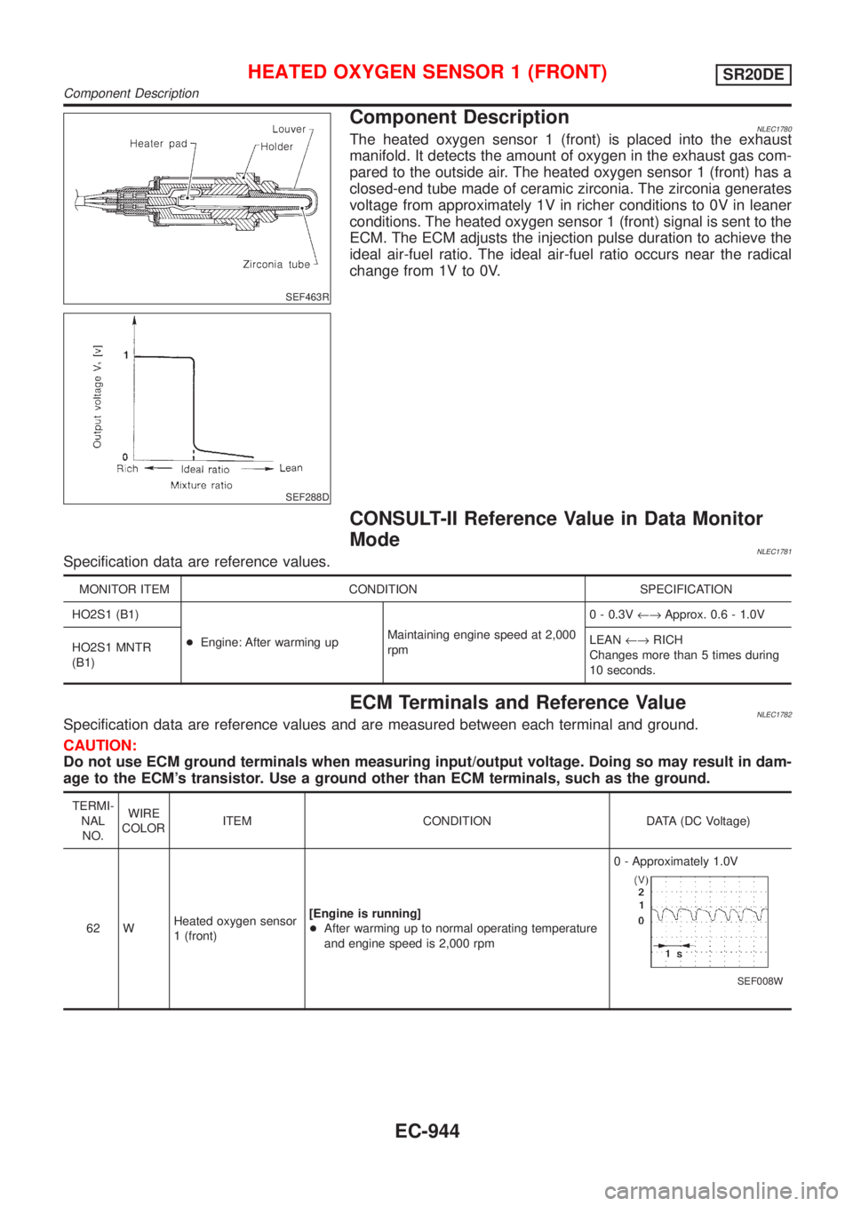
SEF463R
SEF288D
Component DescriptionNLEC1780The heated oxygen sensor 1 (front) is placed into the exhaust
manifold. It detects the amount of oxygen in the exhaust gas com-
pared to the outside air. The heated oxygen sensor 1 (front) has a
closed-end tube made of ceramic zirconia. The zirconia generates
voltage from approximately 1V in richer conditions to 0V in leaner
conditions. The heated oxygen sensor 1 (front) signal is sent to the
ECM. The ECM adjusts the injection pulse duration to achieve the
ideal air-fuel ratio. The ideal air-fuel ratio occurs near the radical
change from 1V to 0V.
CONSULT-II Reference Value in Data Monitor
Mode
NLEC1781Specification data are reference values.
MONITOR ITEM CONDITION SPECIFICATION
HO2S1 (B1)
+Engine: After warming upMaintaining engine speed at 2,000
rpm0 - 0.3V¨Approx. 0.6 - 1.0V
HO2S1 MNTR
(B1)LEAN¨RICH
Changes more than 5 times during
10 seconds.
ECM Terminals and Reference ValueNLEC1782Specification data are reference values and are measured between each terminal and ground.
CAUTION:
Do not use ECM ground terminals when measuring input/output voltage. Doing so may result in dam-
age to the ECM's transistor. Use a ground other than ECM terminals, such as the ground.
TERMI-
NAL
NO.WIRE
COLORITEM CONDITION DATA (DC Voltage)
62 WHeated oxygen sensor
1 (front)[Engine is running]
+After warming up to normal operating temperature
and engine speed is 2,000 rpm0 - Approximately 1.0V
SEF008W
HEATED OXYGEN SENSOR 1 (FRONT)SR20DE
Component Description
EC-944
Page 1370 of 3051
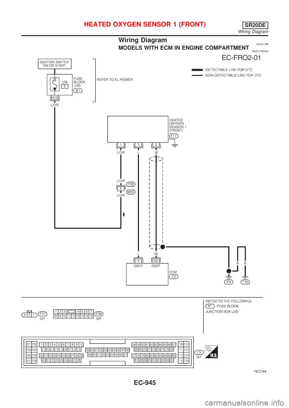
Wiring DiagramNLEC1786MODELS WITH ECM IN ENGINE COMPARTMENTNLEC1786S03
YEC744
HEATED OXYGEN SENSOR 1 (FRONT)SR20DE
Wiring Diagram
EC-945
Trending: bulb, ground clearance, AUX, ABS, radiator cap, lights, buttons


