NISSAN ALMERA TINO 2001 Service Repair Manual
Manufacturer: NISSAN, Model Year: 2001, Model line: ALMERA TINO, Model: NISSAN ALMERA TINO 2001Pages: 3051, PDF Size: 46.38 MB
Page 201 of 3051
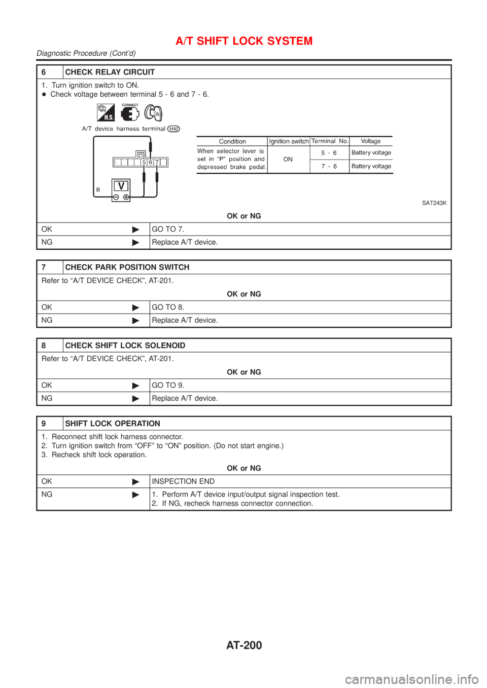
6 CHECK RELAY CIRCUIT
1. Turn ignition switch to ON.
+Check voltage between terminal5-6and7-6.
SAT243K
OK or NG
OK©GO TO 7.
NG©Replace A/T device.
7 CHECK PARK POSITION SWITCH
Refer to ªA/T DEVICE CHECKº, AT-201.
OK or NG
OK©GO TO 8.
NG©Replace A/T device.
8 CHECK SHIFT LOCK SOLENOID
Refer to ªA/T DEVICE CHECKº, AT-201.
OK or NG
OK©GO TO 9.
NG©Replace A/T device.
9 SHIFT LOCK OPERATION
1. Reconnect shift lock harness connector.
2. Turn ignition switch from ªOFFº to ªONº position. (Do not start engine.)
3. Recheck shift lock operation.
OK or NG
OK©INSPECTION END
NG©1. Perform A/T device input/output signal inspection test.
2. If NG, recheck harness connector connection.
A/T SHIFT LOCK SYSTEM
Diagnostic Procedure (Cont'd)
AT-200
Page 202 of 3051
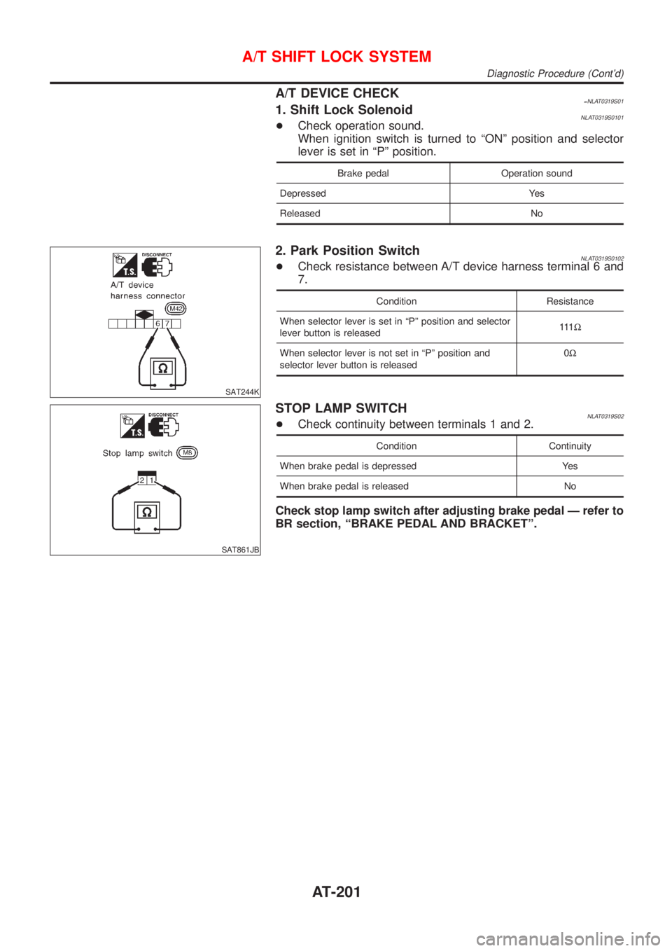
A/T DEVICE CHECK=NLAT0319S011. Shift Lock SolenoidNLAT0319S0101+Check operation sound.
When ignition switch is turned to ªONº position and selector
lever is set in ªPº position.
Brake pedal Operation sound
Depressed Yes
Released No
SAT244K
2. Park Position SwitchNLAT0319S0102+Check resistance between A/T device harness terminal 6 and
7.
Condition Resistance
When selector lever is set in ªPº position and selector
lever button is released111W
When selector lever is not set in ªPº position and
selector lever button is released0W
SAT861JB
STOP LAMP SWITCHNLAT0319S02+Check continuity between terminals 1 and 2.
Condition Continuity
When brake pedal is depressed Yes
When brake pedal is released No
Check stop lamp switch after adjusting brake pedal Ð refer to
BR section, ªBRAKE PEDAL AND BRACKETº.
A/T SHIFT LOCK SYSTEM
Diagnostic Procedure (Cont'd)
AT-201
Page 203 of 3051
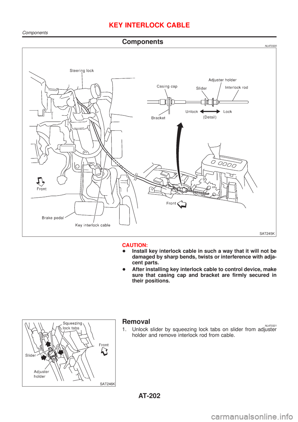
ComponentsNLAT0320
SAT245K
CAUTION:
+Install key interlock cable in such a way that it will not be
damaged by sharp bends, twists or interference with adja-
cent parts.
+After installing key interlock cable to control device, make
sure that casing cap and bracket are firmly secured in
their positions.
SAT246K
RemovalNLAT03211. Unlock slider by squeezing lock tabs on slider from adjuster
holder and remove interlock rod from cable.
KEY INTERLOCK CABLE
Components
AT-202
Page 204 of 3051
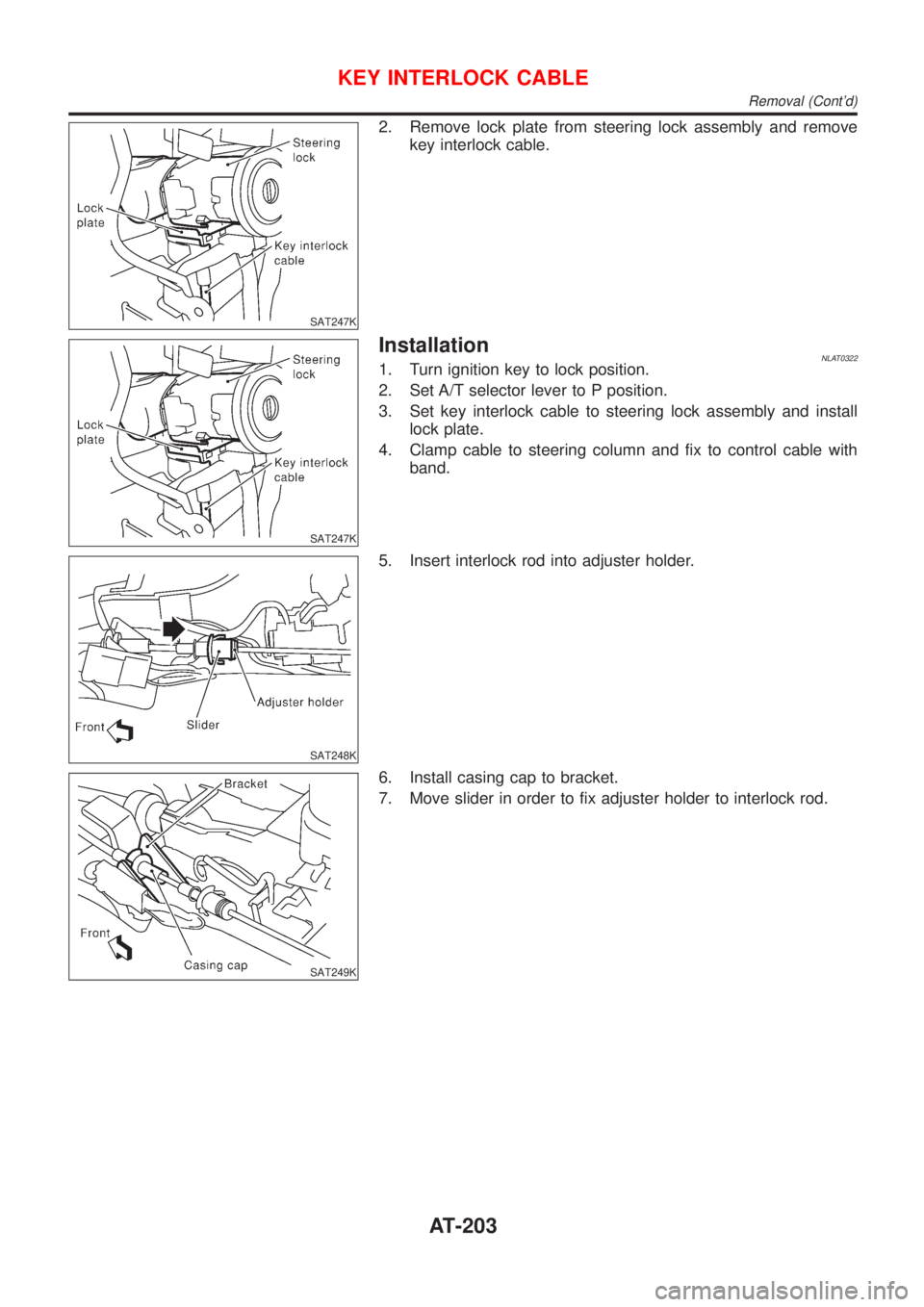
SAT247K
2. Remove lock plate from steering lock assembly and remove
key interlock cable.
SAT247K
InstallationNLAT03221. Turn ignition key to lock position.
2. Set A/T selector lever to P position.
3. Set key interlock cable to steering lock assembly and install
lock plate.
4. Clamp cable to steering column and fix to control cable with
band.
SAT248K
5. Insert interlock rod into adjuster holder.
SAT249K
6. Install casing cap to bracket.
7. Move slider in order to fix adjuster holder to interlock rod.
KEY INTERLOCK CABLE
Removal (Cont'd)
AT-203
Page 205 of 3051
SAT658J
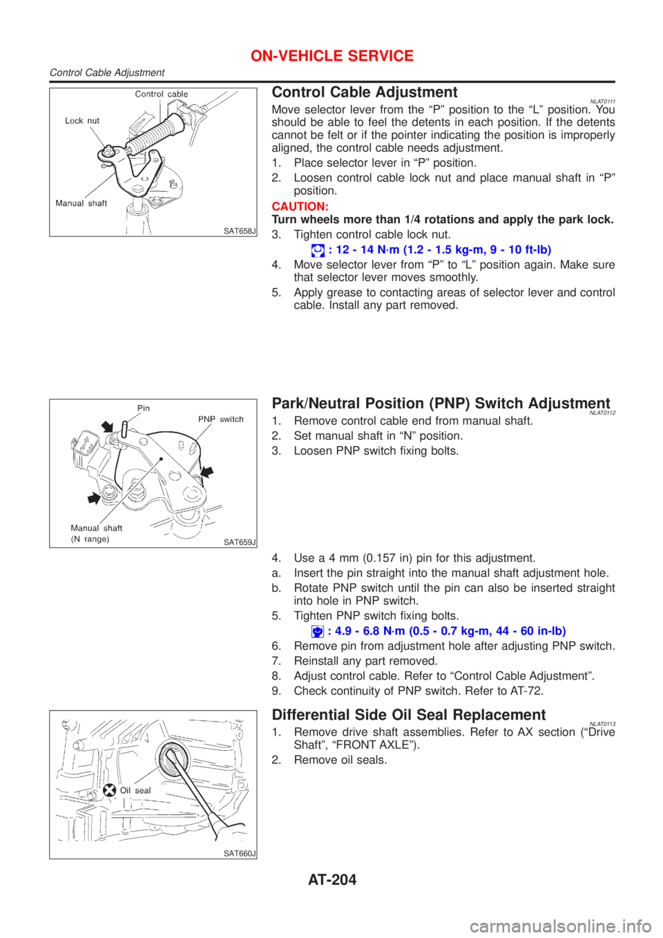
Control Cable AdjustmentNLAT0111Move selector lever from the ªPº position to the ªLº position. You
should be able to feel the detents in each position. If the detents
cannot be felt or if the pointer indicating the position is improperly
aligned, the control cable needs adjustment.
1. Place selector lever in ªPº position.
2. Loosen control cable lock nut and place manual shaft in ªPº
position.
CAUTION:
Turn wheels more than 1/4 rotations and apply the park lock.
3. Tighten control cable lock nut.
: 12 - 14 N´m (1.2 - 1.5 kg-m,9-10ft-lb)
4. Move selector lever from ªPº to ªLº position again. Make sure
that selector lever moves smoothly.
5. Apply grease to contacting areas of selector lever and control
cable. Install any part removed.
SAT659J
Park/Neutral Position (PNP) Switch AdjustmentNLAT01121. Remove control cable end from manual shaft.
2. Set manual shaft in ªNº position.
3. Loosen PNP switch fixing bolts.
4. Usea4mm(0.157 in) pin for this adjustment.
a. Insert the pin straight into the manual shaft adjustment hole.
b. Rotate PNP switch until the pin can also be inserted straight
into hole in PNP switch.
5. Tighten PNP switch fixing bolts.
: 4.9 - 6.8 N´m (0.5 - 0.7 kg-m, 44 - 60 in-lb)
6. Remove pin from adjustment hole after adjusting PNP switch.
7. Reinstall any part removed.
8. Adjust control cable. Refer to ªControl Cable Adjustmentº.
9. Check continuity of PNP switch. Refer to AT-72.
SAT660J
Differential Side Oil Seal ReplacementNLAT01131. Remove drive shaft assemblies. Refer to AX section (ªDrive
Shaftº, ªFRONT AXLEº).
2. Remove oil seals.
ON-VEHICLE SERVICE
Control Cable Adjustment
AT-204
Page 206 of 3051
SAT661JB
3. Install oil seals.
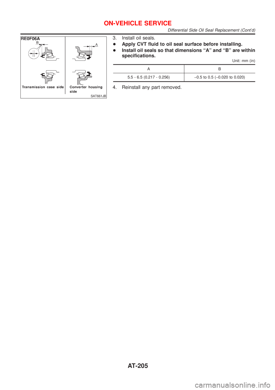
+Apply CVT fluid to oil seal surface before installing.
+Install oil seals so that dimensions ªAº and ªBº are within
specifications.
Unit: mm (in)
AB
5.5 - 6.5 (0.217 - 0.256) þ0.5 to 0.5 (þ0.020 to 0.020)
4. Reinstall any part removed.
ON-VEHICLE SERVICE
Differential Side Oil Seal Replacement (Cont'd)
AT-205
Page 207 of 3051
SAT664J
RemovalNLAT0115CAUTION:
Before separating transaxle from engine, remove the crank-
shaft position sensor (OBD) from transaxle. Be careful not to
damage sensor.
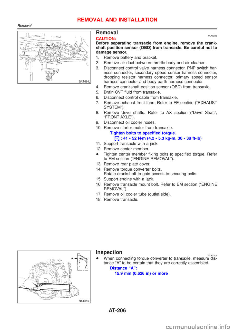
1. Remove battery and bracket.
2. Remove air duct between throttle body and air cleaner.
3. Disconnect control valve harness connector, PNP switch har-
ness connector, secondary speed sensor harness connector,
dropping resistor harness connector, primary speed sensor
harness connector and body earth harness connector.
4. Remove crankshaft position sensor (OBD) from transaxle.
5. Drain CVT fluid from transaxle.
6. Disconnect control cable from transaxle.
7. Remove exhaust front tube. Refer to FE section (ªEXHAUST
SYSTEMº).
8. Remove drive shafts. Refer to AX section (ªDrive Shaftº,
ªFRONT AXLEº).
9. Disconnect oil cooler hoses.
10. Remove starter motor from transaxle.
Tighten bolts to specified torque.
: 41 - 52 N´m (4.2 - 5.3 kg-m, 30 - 38 ft-lb)
11. Support transaxle with a jack.
12. Remove center member.
+Tighten center member fixing bolts to specified torque, Refer
to EM section (ªENGINE REMOVALº).
13. Remove rear plate cover.
14. Remove torque converter bolts.
Rotate crankshaft to gain access to securing bolts.
15. Support engine with a jack.
16. Remove transaxle mount bolt. Refer to EM section (ªENGINE
REMOVALº).
17. Remove oil cooler tube (outlet side).
18. Remove transaxle.
SAT665J
InspectionNLAT0236+When connecting torque converter to transaxle, measure dis-
tance ªAº to be certain that they are correctly assembled.
Distance ªAº:
15.9 mm (0.626 in) or more
REMOVAL AND INSTALLATION
Removal
AT-206
Page 208 of 3051
SAT266K
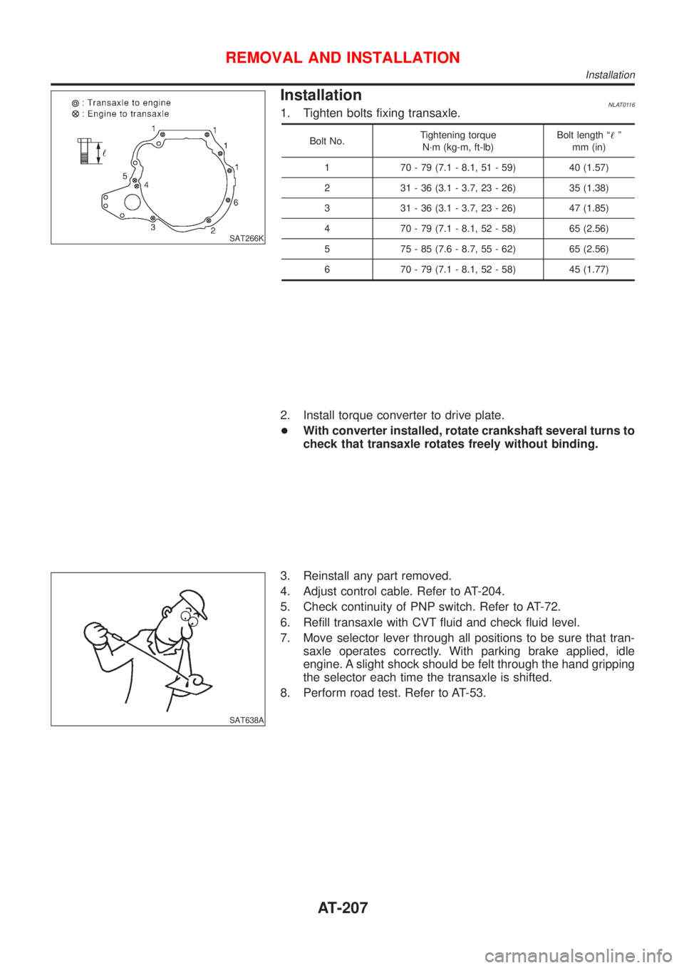
InstallationNLAT01161. Tighten bolts fixing transaxle.
Bolt No.Tightening torque
N´m (kg-m, ft-lb)Bolt length ª!º
mm (in)
1 70 - 79 (7.1 - 8.1, 51 - 59) 40 (1.57)
2 31 - 36 (3.1 - 3.7, 23 - 26) 35 (1.38)
3 31 - 36 (3.1 - 3.7, 23 - 26) 47 (1.85)
4 70 - 79 (7.1 - 8.1, 52 - 58) 65 (2.56)
5 75 - 85 (7.6 - 8.7, 55 - 62) 65 (2.56)
6 70 - 79 (7.1 - 8.1, 52 - 58) 45 (1.77)
2. Install torque converter to drive plate.
+With converter installed, rotate crankshaft several turns to
check that transaxle rotates freely without binding.
SAT638A
3. Reinstall any part removed.
4. Adjust control cable. Refer to AT-204.
5. Check continuity of PNP switch. Refer to AT-72.
6. Refill transaxle with CVT fluid and check fluid level.
7. Move selector lever through all positions to be sure that tran-
saxle operates correctly. With parking brake applied, idle
engine. A slight shock should be felt through the hand gripping
the selector each time the transaxle is shifted.
8. Perform road test. Refer to AT-53.
REMOVAL AND INSTALLATION
Installation
AT-207
Page 209 of 3051
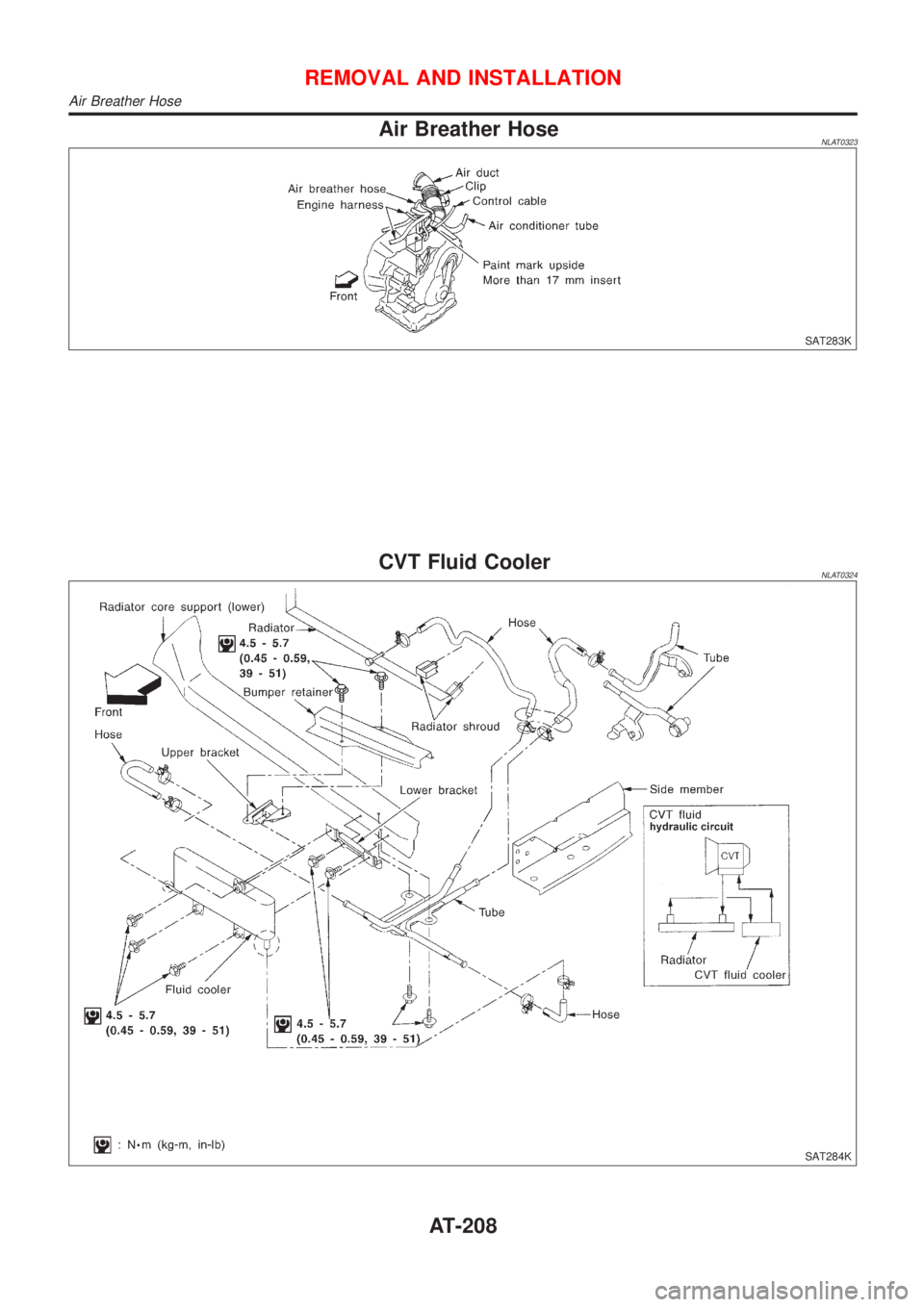
Air Breather HoseNLAT0323
SAT283K
CVT Fluid CoolerNLAT0324
SAT284K
REMOVAL AND INSTALLATION
Air Breather Hose
AT-208
Page 210 of 3051
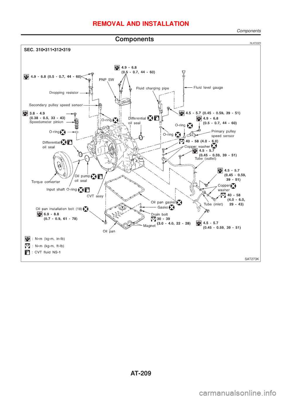
ComponentsNLAT0325
SAT273K
REMOVAL AND INSTALLATION
Components
AT-209