NISSAN ALMERA TINO 2001 Service Repair Manual
ALMERA TINO 2001
NISSAN
NISSAN
https://www.carmanualsonline.info/img/5/57352/w960_57352-0.png
NISSAN ALMERA TINO 2001 Service Repair Manual
Trending: brake fluid, turn signal bulb, brake, ad blue, air filter, jacking points, maintenance
Page 2971 of 3051
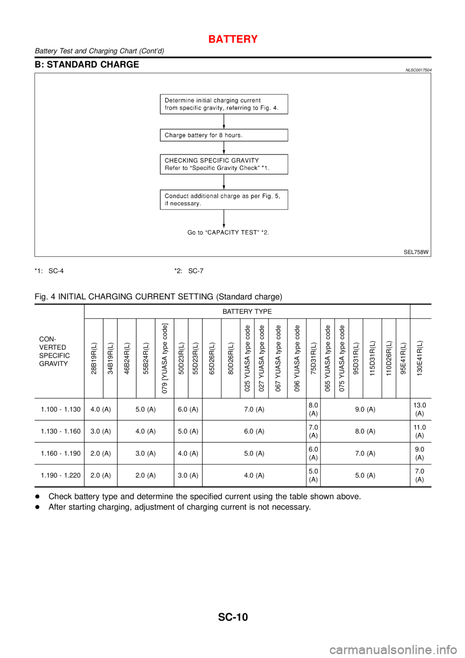
B: STANDARD CHARGENLSC0017S04
SEL758W
*1: SC-4 *2: SC-7
Fig. 4 INITIAL CHARGING CURRENT SETTING (Standard charge)
CON-
VERTED
SPECIFIC
GRAVITYBATTERY TYPE
28B19R(L)
34B19R(L)
46B24R(L)
55B24R(L)
079 [YUASA type code]
50D23R(L)
55D23R(L)
65D26R(L)
80D26R(L)
025 YUASA type code
027 YUASA type code
067 YUASA type code
096 YUASA type code
75D31R(L)
065 YUASA type code
075 YUASA type code
95D31R(L)
115D31R(L)
110D26R(L)
95E41R(L)
130E41R(L)
1.100 - 1.130 4.0 (A) 5.0 (A) 6.0 (A) 7.0 (A)8.0
(A)9.0 (A)13.0
(A)
1.130 - 1.160 3.0 (A) 4.0 (A) 5.0 (A) 6.0 (A)7.0
(A)8.0 (A)11.0
(A)
1.160 - 1.190 2.0 (A) 3.0 (A) 4.0 (A) 5.0 (A)6.0
(A)7.0 (A)9.0
(A)
1.190 - 1.220 2.0 (A) 2.0 (A) 3.0 (A) 4.0 (A)5.0
(A)5.0 (A)7.0
(A)
+Check battery type and determine the specified current using the table shown above.
+After starting charging, adjustment of charging current is not necessary.
BATTERY
Battery Test and Charging Chart (Cont’d)
SC-10
Page 2972 of 3051
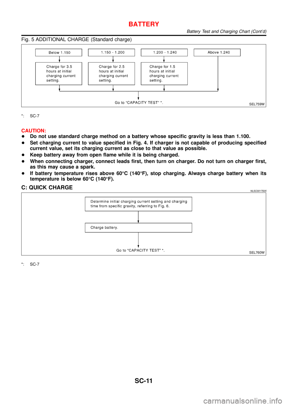
Fig. 5 ADDITIONAL CHARGE (Standard charge)
SEL759W
*: SC-7
CAUTION:
+Do not use standard charge method on a battery whose specific gravity is less than 1.100.
+Set charging current to value specified in Fig. 4. If charger is not capable of producing specified
current value, set its charging current as close to that value as possible.
+Keep battery away from open flame while it is being charged.
+When connecting charger, connect leads first, then turn on charger. Do not turn on charger first,
as this may cause a spark.
+If battery temperature rises above 60°C (140°F), stop charging. Always charge battery when its
temperature is below 60°C (140°F).
C: QUICK CHARGENLSC0017S05
SEL760W
*: SC-7
BATTERY
Battery Test and Charging Chart (Cont’d)
SC-11
Page 2973 of 3051
![NISSAN ALMERA TINO 2001 Service Repair Manual Fig. 6 INITIAL CHARGING CURRENT SETTING AND CHARGING TIME (Quick charge)
BATTERY
TYPE
28B19R(L)
34B19R(L)
46B24R(L)
55B24R(L)
50D23R(L)
079 [YUASA type code]
55D23R(L)
65D26R(L)
80D26R(L)
025 [YUASA t NISSAN ALMERA TINO 2001 Service Repair Manual Fig. 6 INITIAL CHARGING CURRENT SETTING AND CHARGING TIME (Quick charge)
BATTERY
TYPE
28B19R(L)
34B19R(L)
46B24R(L)
55B24R(L)
50D23R(L)
079 [YUASA type code]
55D23R(L)
65D26R(L)
80D26R(L)
025 [YUASA t](/img/5/57352/w960_57352-2972.png)
Fig. 6 INITIAL CHARGING CURRENT SETTING AND CHARGING TIME (Quick charge)
BATTERY
TYPE
28B19R(L)
34B19R(L)
46B24R(L)
55B24R(L)
50D23R(L)
079 [YUASA type code]
55D23R(L)
65D26R(L)
80D26R(L)
025 [YUASA type code]
027 [YUASA type code]
065 [YUASA type code]
075 [YUASA type code]
067 [YUASA type code]
096 [YUASA type code]
75D31R(L)
95D31R(L)
115D31R(L)
110D26R(L)
95E41R(L)
130E41R(L)
CURRENT
[A]10 (A) 15 (A) 20 (A) 25 (A) 30 (A)40
(A)
CONVERTED SPECIFIC GRAVITY
1.100 -
1.1302.5 hours
1.130 -
1.1602.0 hours
1.160 -
1.1901.5 hours
1.190 -
1.2201.0 hours
Above
1.2200.75 hours (45 min.)
+Check battery type and determine the specified current using the table shown above.
+After starting charging, adjustment of charging current is not necessary.
CAUTION:
+Do not use quick charge method on a battery whose specific gravity is less than 1.100.
+Set initial charging current to value specified in Fig. 6. If charger is not capable of producing
specified current value, set its charging current as close to that value as possible.
+Keep battery away from open flame while it is being charged.
+When connecting charger, connect leads first, then turn on charger. Do not turn on charger first,
as this may cause a spark.
+Be careful of a rise in battery temperature because a large current flow is required during quick-
charge operation.
If battery temperature rises above 60°C (140°F), stop charging. Always charge battery when its
temperature is below 60°C (140°F).
+Do not exceed the charging time specified in Fig. 6, because charging battery over the charging
time can cause deterioration of the battery.
BATTERY
Battery Test and Charging Chart (Cont’d)
SC-12
Page 2974 of 3051
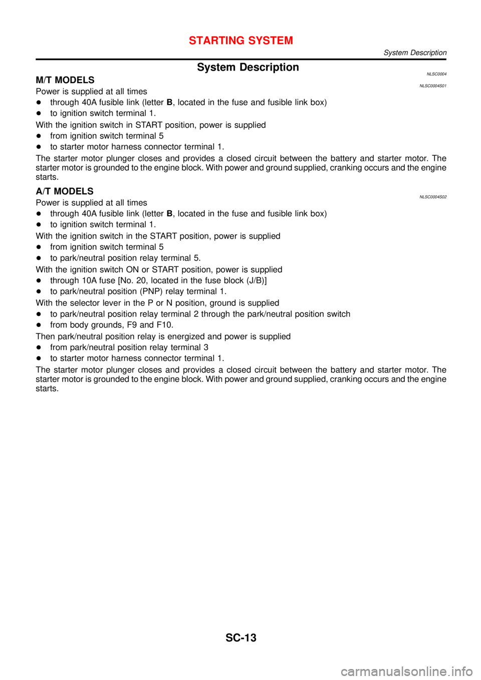
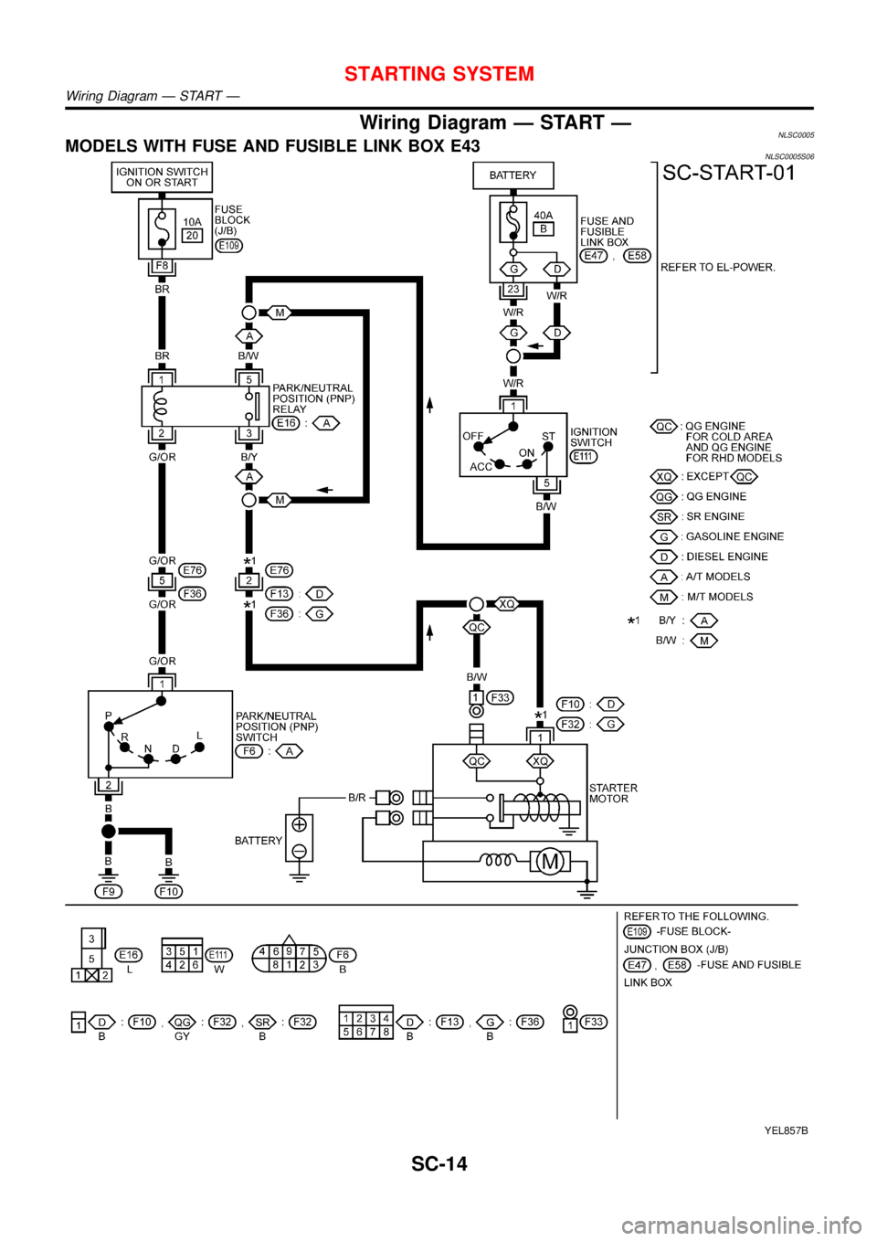
System DescriptionNLSC0004M/T MODELSNLSC0004S01Power is supplied at all times
+through 40A fusible link (letterB, located in the fuse and fusible link box)
+to ignition switch terminal 1.
With the ignition switch in START position, power is supplied
+from ignition switch terminal 5
+to starter motor harness connector terminal 1.
The starter motor plunger closes and provides a closed circuit between the battery and starter motor. The
starter motor is grounded to the engine block. With power and ground supplied, cranking occurs and the engine
starts.
A/T MODELSNLSC0004S02Power is supplied at all times
+through 40A fusible link (letterB, located in the fuse and fusible link box)
+to ignition switch terminal 1.
With the ignition switch in the START position, power is supplied
+from ignition switch terminal 5
+to park/neutral position relay terminal 5.
With the ignition switch ON or START position, power is supplied
+through 10A fuse [No. 20, located in the fuse block (J/B)]
+to park/neutral position (PNP) relay terminal 1.
With the selector lever in the P or N position, ground is supplied
+to park/neutral position relay terminal 2 through the park/neutral position switch
+from body grounds, F9 and F10.
Then park/neutral position relay is energized and power is supplied
+from park/neutral position relay terminal 3
+to starter motor harness connector terminal 1.
The starter motor plunger closes and provides a closed circuit between the battery and starter motor. The
starter motor is grounded to the engine block. With power and ground supplied, cranking occurs and the engine
starts.
STARTING SYSTEM
System Description
SC-13
Page 2975 of 3051
Wiring Diagram—START—NLSC0005MODELS WITH FUSE AND FUSIBLE LINK BOX E43NLSC0005S06
YEL857B
STARTING SYSTEM
Wiring Diagram—START—
SC-14
Page 2976 of 3051
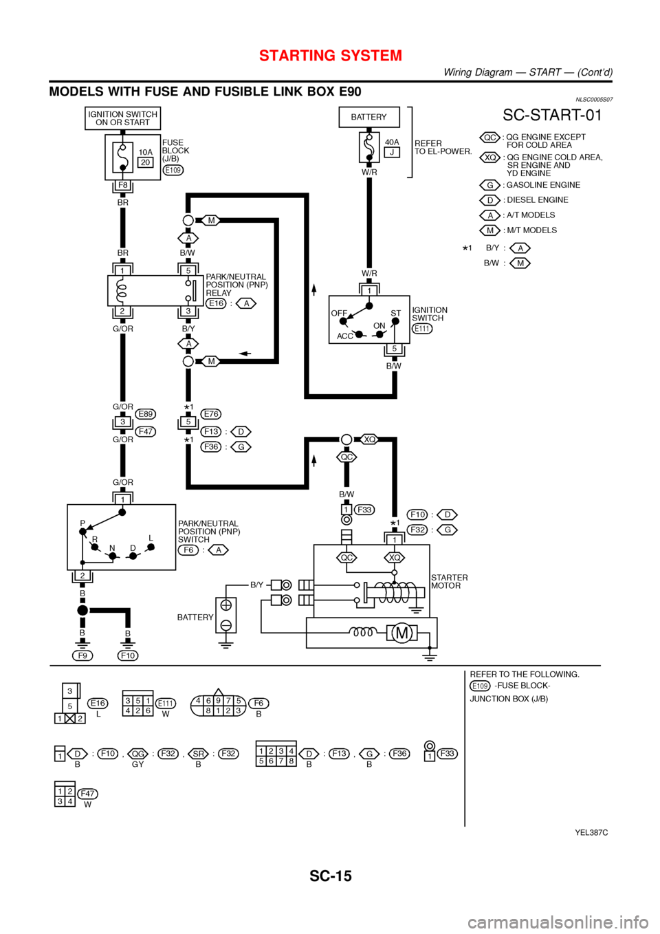
MODELS WITH FUSE AND FUSIBLE LINK BOX E90NLSC0005S07
YEL387C
STARTING SYSTEM
Wiring Diagram—START—(Cont’d)
SC-15
Page 2977 of 3051
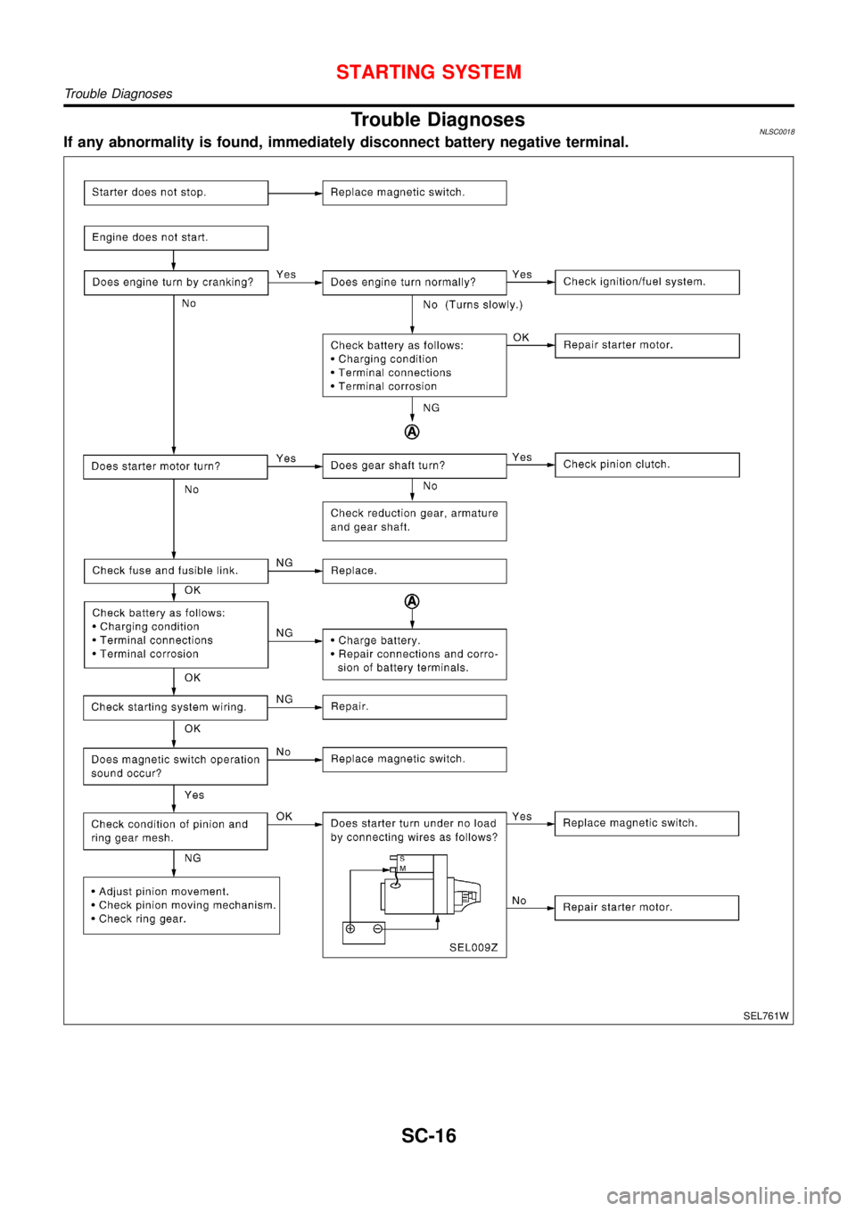
Trouble DiagnosesNLSC0018If any abnormality is found, immediately disconnect battery negative terminal.
SEL761W
STARTING SYSTEM
Trouble Diagnoses
SC-16
Page 2978 of 3051
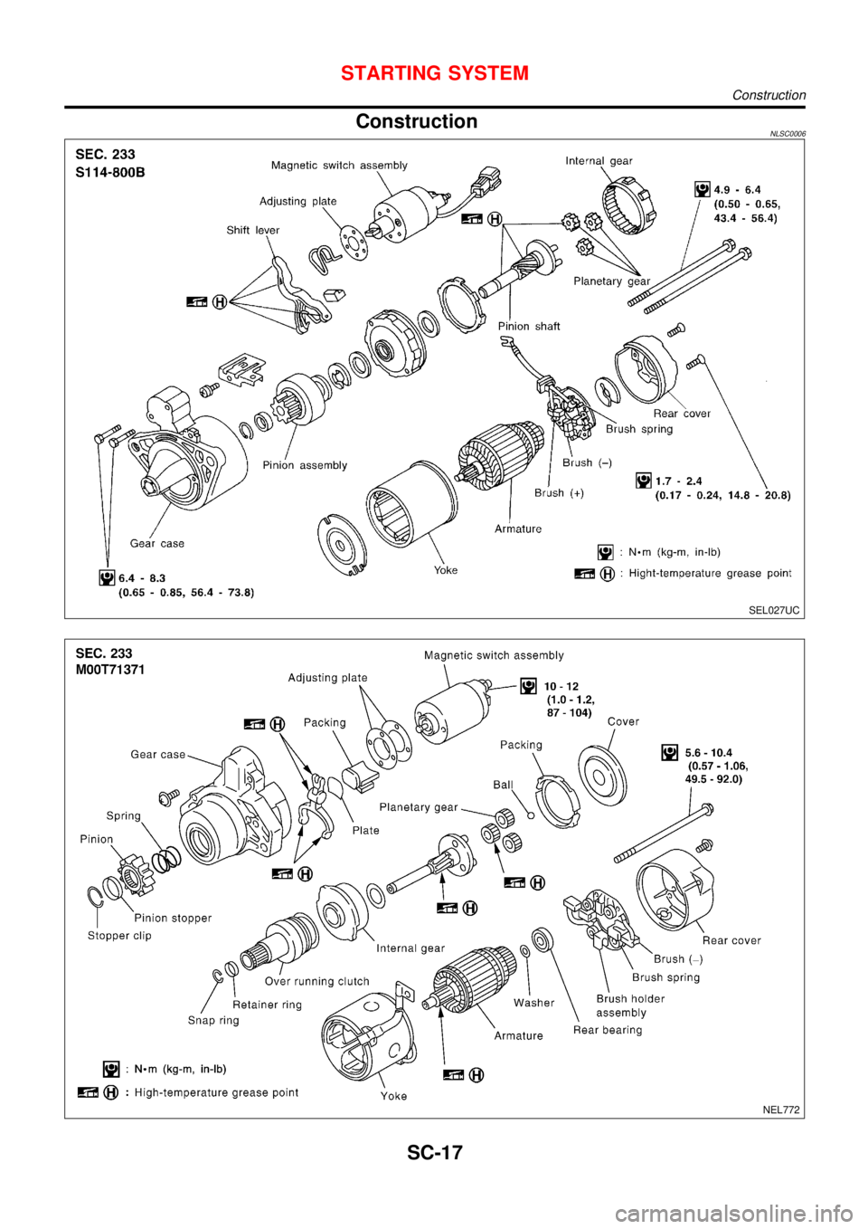
ConstructionNLSC0006
SEL027UC
NEL772
STARTING SYSTEM
Construction
SC-17
Page 2979 of 3051
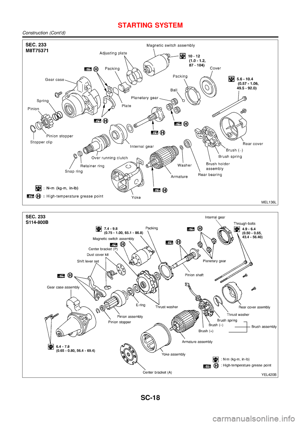
MEL136L
YEL420B
STARTING SYSTEM
Construction (Cont’d)
SC-18
Page 2980 of 3051
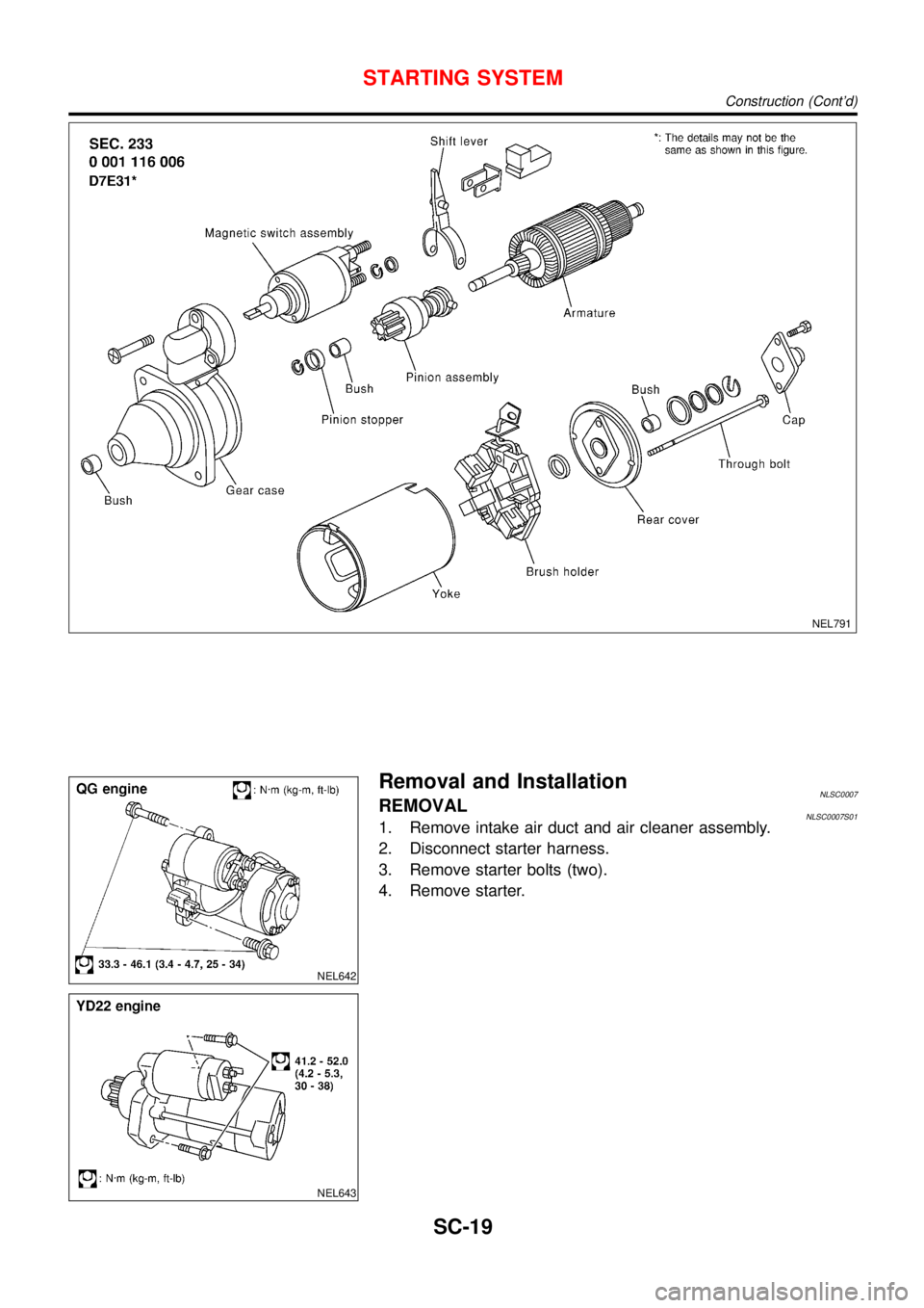
NEL791
NEL642
NEL643
Removal and InstallationNLSC0007REMOVALNLSC0007S011. Remove intake air duct and air cleaner assembly.
2. Disconnect starter harness.
3. Remove starter bolts (two).
4. Remove starter.
STARTING SYSTEM
Construction (Cont’d)
SC-19
Trending: airbag off, clutch, inflation pressure, lock, belt, wheelbase, octane
![NISSAN ALMERA TINO 2001 Service Repair Manual Fig. 6 INITIAL CHARGING CURRENT SETTING AND CHARGING TIME (Quick charge)
BATTERY
TYPE
28B19R(L)
34B19R(L)
46B24R(L)
55B24R(L)
50D23R(L)
079 [YUASA type code]
55D23R(L)
65D26R(L)
80D26R(L)
025 [YUASA t NISSAN ALMERA TINO 2001 Service Repair Manual Fig. 6 INITIAL CHARGING CURRENT SETTING AND CHARGING TIME (Quick charge)
BATTERY
TYPE
28B19R(L)
34B19R(L)
46B24R(L)
55B24R(L)
50D23R(L)
079 [YUASA type code]
55D23R(L)
65D26R(L)
80D26R(L)
025 [YUASA t](/img/5/57352/w960_57352-2972.png)

