NISSAN GT-R 1998 Service Manual
Manufacturer: NISSAN, Model Year: 1998, Model line: GT-R, Model: NISSAN GT-R 1998Pages: 230, PDF Size: 12.66 MB
Page 191 of 230
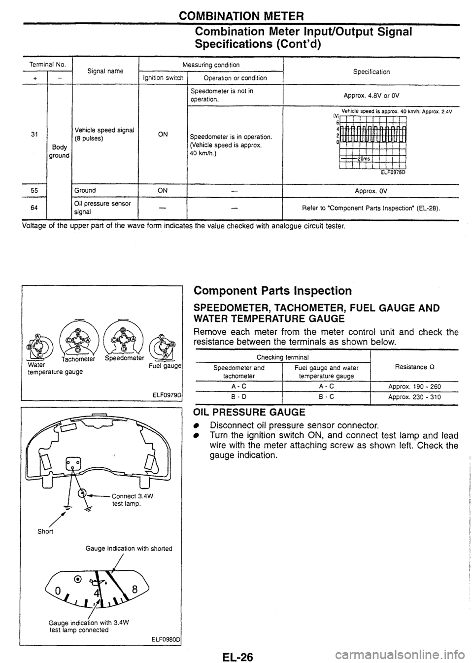
COMBINATION METER
Combination Meter Input/Output Signal -
Specifications (~ont'd)
Signal name
Vehicle speed signal
(8 pulses)
Body
ground
Ground
I--
Oil pressure sensor
signal Measuring
condi!ion
operation.
Speedometer is in operation.
(Vehicle speed is approx.
40 km~h.)
Specification
Approx.
4.8V or OV
Vehicle speed is approx. 40
ELF0978D
-- - Approx. 2.4V
ON - Approx. OV
- I - I Refer to 'Component Parts Inspection" (EL-28).
J I I Voltage of the upper part of the wave form indicates the value checked with analogue circuit tester.
- Water Fuel gaugc
temperature gauge
1 Gauge indication with shorted
Gauge
indicaion with
3.4W test lamp connected
ELF0980D
Component Parts inspection
SPEEDOMETER, TACHOMETER, FUEL GAUGE AND
WATER TEMPERATURE
GAUGE
Remove each meter from the meter control unit and check the
resistance between the terminals as shown below.
Checkina terminal I
Speedometer and I Fuel gauge and water I Resistance R
B-D I B-C I Approx. 230 - 310
tachometer
A-C
OIL PRESSURE GAUGE
Disconnect oil pressure sensor connector.
Turn the ignition switch ON, and connect test lamp and lead
wire with the meter attaching screw as shown left. Check the
gauge indication.
temperature gauge
A-C
ADD~OX.
190 - 260
Page 192 of 230

COMBINATION METER
Component Parts Inspection (Cont'd)
Fuel gauge unit harness
connector
Lower side
<
I
I
I
(Full) Lead switch
harness connector
on fuel gauge unit
h L Upper side
Harness connec:or on lead sw~lch
With fuel
T/f Without fuel
Lower side
(Empty)
FUEL GAUGE UNIT
Remove fuel gauge unit from the vehicle.
Check the gauge resistance on the gauge with the fuel gauge
at Empty and then Full.
SD
LEAD SWITCH
Remove fuel gauge unit from the vehicle.
Check continuity between terminals on the lead switches in the
tank.
Terminal No.
1-3
Termina! No. I Condition I Continuity
Float position
Full
Empty
THERMAL
TRANSMITER
Resistance R
Approx. 6 max.
Approx. 80 min.
5 - 7 6-7
0 When the engine has warmed up to approx. 80°C, measure
resistance between thermal transmitter and body ground.
Specification: Approx. 76 - 90Q
There is no continuity when approx. 26 of fuel is left in the sub fuel tank.
With fuel
Without fuel Yes
No
Page 193 of 230
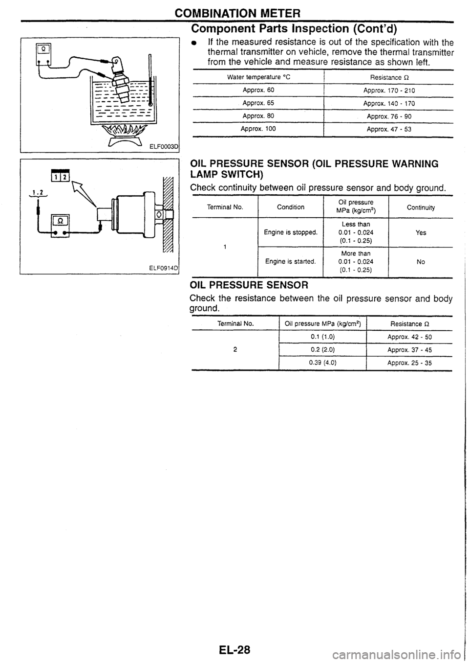
COMBINATION METER
Component Parts Inspection (Cont'd)
If the measured resistance is out of the specification with the
thermal transmitter on vehicle, remove the thermal transmitter
from the vehicle and measure resistance as
shown left.
Water temperature "C 1 Resistance R
Approx. 60 I Approx. i70 - 21 0
Approx. 65 I Approx. 140 - 170
Approx. 80 I Approx. 76 - 90
I
- - -- Appro~. 100 Approx. 47 - 53
OIL PRESSURE SENSOR (OIL PRESSURE WARNING
LAMP SWITCH)
Check continuity between oil pressure sensor and body ground.
Terminal No.
OIL PRESSURE SENSOR
Engine is stopped.
Engine is started.
Check the resistance between the oil pressure sensor and body
ground.
Condition
Terminal No.
I Oil pressure MPa (kgkmq-1 Resistance R
Oil pressure
MPa (kg/cm2) 1 Continuity
Less than
0.01 - 0.024
(0.1 - 0.25)
More than 0.01 - 0.024
(0.1 - 0.25)
0.2 (2.0) Approx. 37 - 45
Yes
No
Page 194 of 230
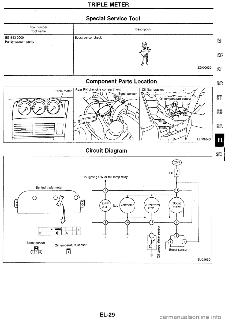
TRIPLE METER
Special Service Tool
Tool number
Tool name Description
i
€GI 51 3 0000 Boost sensor
check
Handy vacuum pump
Component Parts Location
Triple meter
I
Circuit Diagram
Behind triple meter
h
To lighting SW or tail lamp relay
Boost sensor
Oil temperature sensor
* BOOS^ sensor
Page 195 of 230
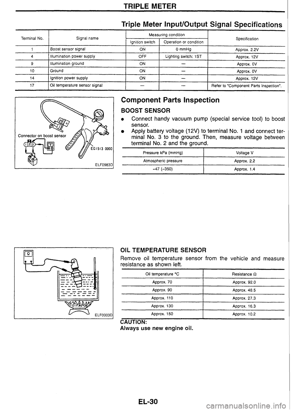
TRIPLE METER
Triple Meter InputlOutput Signal Specifications
Component
Parts Inspection
Terminal No.
1
4
9
10
14
17
BOOST SENSOR
Connect handy vacuum pump (special service tool) to boost
sensor.
Apply battery voltage (12V) to terminal No. 1 and connect ter-
minal No.
3 to the ground. Then, measure voltage between
terminal No.
2 and the ground.
I I - I Refer to "Component Parts Inspectionn.
Signal
name
Boost sensor signal
Illumination
power
supply
illumination ground
Ground ignition power supply
Oil temperature sensor signal
Pressure
kPa (mmHg) I Voltage V
I
- pp Atmospheric pressure Approx. 2.2
-47 (-350) 1 Approx. 1.4
-
Specification
Approx. 2.2V
Approx. 12V
Approx. OV
Approx.
OV
Approx. 12V
Measuring condition
OIL TEMPERATURE SENSOR
lgnition
switch
ON
OFF
ON
ON
ON
Remove oil temperature sensor from the vehicle and measure
resistance as shown
left.
Operation or condition
0 mmHg
Lighting switch: 1
ST
-
-
-
Oil temperature "C
Approx. 70
-- - - --
Resistance R
Approx. 92.0
Approx. 90
Approx.
110
Approx. 130 - -- Appro~. 48.5
Approx. 27.3
Approx. 16.3
Approx. 150
Approx. 10.2
CAUTION:
Always use new engine
oil.
Page 196 of 230

IGNITION KEY WARNING BUZZER AND LIGHT WARNING BUZZER
I Behind combination meter
Meter control unit Component Parts Location
J
Circuit Diagram
Meter Control Unit
InputlOutput Signal
Specifications
Terminal No.
Driver door switch signal
Signal
name
OFF Measuring condition
Ignition switch
I Measuring method Specification
Driver door switch
29
ON (Open)
OFF (Closed)
42
Approx. OV
Approx. 12V
Ignition power supply
54
55
Key-in detection switch
signal 1 OFF
ON
Lighting switch signal
Ground Approx. 12V
Remove
the ignition key.
Insert the ignition key. Approx. OV
Approx. 12V
Approx. 12V
Approx. OV
Approx. OV
I
OFF
ON Lighting
switch: 1 ST ON
OFF
-
Page 197 of 230

FRONT WIPER
Front wiper amplifier
Component Parts Location
Circuit Diagram
Front wiper motor Front wiper and washer
SW
Washer motor
---------------- HI
EL-17040
Front Wiper InpWOutput Signal Specifications
Terminal No.
Signal name 1 Measuring condition. I
Wiper motor position detection
signal
1 Specification
Wiper switch: LO position
Ignition switch
(Reference)
I
Operation
Wiper motor LO signal
4 Wiper motor HI signal
Wiper switch
6
ON
OFF
.
Lo
7 1 Washer operation detection signal I ON
8 I Ignition power supply I ON I - I Approx. 12V
Approx. 12V
ADDIOX. OV
-
Wiper switch
I
Washer motor is in operation. I I
I - Ground
Approx.
OV
I Washer motor is not in operation. OFF
HI
. .
Approx. OV
ON
Approx.
12V
Approx. 12V
Approx. OV
Page 198 of 230

REAR WIPER
Component
Parts Location
Rear of suspension tower (RH)
Circuit Diagram
IGN :
Q
Rear washer motor
B Rear wiper motor I-
Washer motor operation
detection signal I
1 Rear wiper and washer SW
Intermittent position de!ection signal I ~SHIOFFI 111~~ INTI - ON IWIW~
I * Wiper motor operation signal
Rear Wiper Amplifier InputlOutput Signal
Specifications
Measuring condition
lanition
switch
/ O~eration
Terminal No.
Signal name Specification
Washer motor operation detection
signal
Wiper operation signal
Ground
Intermittent position detection signal
I ON I Wiper switch
Wlper
motor operation signal ON
ON
ON
ACC power
supply
I I I (Reference)
INT . Other than INT
Washer
motor is in operation.
Washer motor is not in operation.
Wiper motor is in operation.
Wiper motor is not
in operation.
-
Approx. OV
ARD~OX. 12V Approx.
OV
Approx.
12V
Approx. OV
Approx.
12V
AD~rox. OV
. .
Approx. 12V 1 I ON -
Page 199 of 230
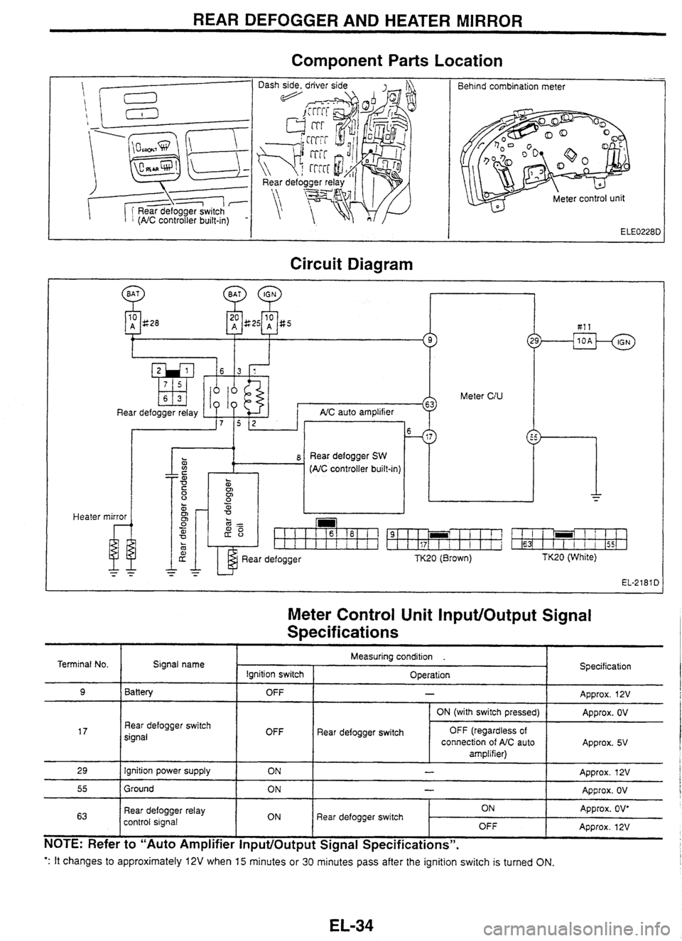
REAR DEFOGGER AND HEATER MIRROR
Component
Parts Location
-- Behind combination meter
Circuit Diagram
Heater
10 A g28 81 1
Meter CIU
Rear defogger relay AIC auto ampl~f~er
. 0
z i 8 Rear defogger SW a (AC controller built-m)
mirror
u
Rear defogger TK20 (Brown) TK20 (White)
EL-2181 D
Meter Control Unit InputlOutput Signal
S~ecif ications
': It changes to approximately 12V when 15 minutes or 30 minutes pass after the ignition switch is turned ON.
Terminal No.
9
17
29
55
63
NOTE: Refer to "Auto Amplifier InputlOutput Signal Specifications".
Signal name
Battery
Rear defogger switch
signal
Ignition power supply
Ground
Rear defogger relay
control signal Specification
Approx.
12V
Approx. OV
Approx. 5V
Approx. 12V
Approx. OV
Approx. OV*
Approx. 12V
Measuring condition .
Ignition switch OFF
OFF ON
ON
ON Operation
-
Rear
defogger switch ON (with switch
pressed)
OFF (regardless of
connection of AIC auto
amplifier)
-
-
Rear defogger switch ON OFF
Page 200 of 230

WIPER DEICER
Component
Parts Location
Wiper deicer switch I
/ I Wiper deicer switch
Circuit Diagram
m
Wiper deicer relay
Wiper deicer Wiper deicer
SW (Timer
built-in) lighting
Wiper
Deicer Switch InputlOutput Signal
Specifications
Terminal No. Signal name
Indicator power supply Measuring
condition .
Ignition switch I Operation Specification
Wiper deicer switch
2
3
OFF
ON
4
- Approx. OV
Approx. 12V
lllumination ground
Ground
5
1 Approx. 12V lgn~tion power supply
6
OFF
ON
Wiper deicer relay control
signal
I ON 1 Wiper deicer switch
ON
*: When
the wiper deicer is activated (approx. 15 minutes).
Illumination power supply
-- -
- - - - - -
ON
OFF
- Approx. OV
Approx. OV
Approx. OV'
Approx. 12V
OFF Lighting
switch: 1ST -- - Approx. 12V