NISSAN GT-R 1998 Service Manual
Manufacturer: NISSAN, Model Year: 1998, Model line: GT-R, Model: NISSAN GT-R 1998Pages: 230, PDF Size: 12.66 MB
Page 151 of 230

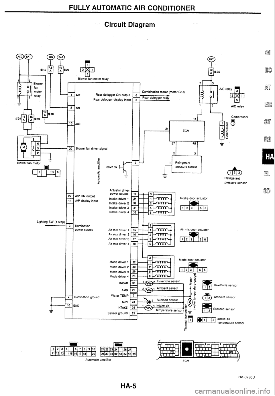
FULLY AUTOMATIC AIR CONDITIONER
Circuit
Diagram
Blower tan motor relay
Rear defogger
A Combination meter (meter UU) output * I Rear defogger relay - Rear defogger display inpui
I Compressor
Blower
fan driver signal Refrigerant Pressure sensor
Actuator driver power source
lntake driver
1 lntake driver 2 lntake driver 3 lntake driver 4
lntake door actuator NP ON output NP display input
Lighting
SW (1 step)
Y-lkEka Air mix door actuator
Illumination
power
source
Air mix driver 1 Air mrx drive: 2 Air mix driver 3 Air mix driver 4
Mode driver 1 1 Mode driver 2 Mode driver 3 Mode driver 4
INCAR In-vehicle sensor
Ambienl sensor
Sunload sensor
AM B
Water TEMP
SUN
INTAKE
Sensor around
lluminatron
groun:!
iND
Automatic
amp!iher
Page 152 of 230

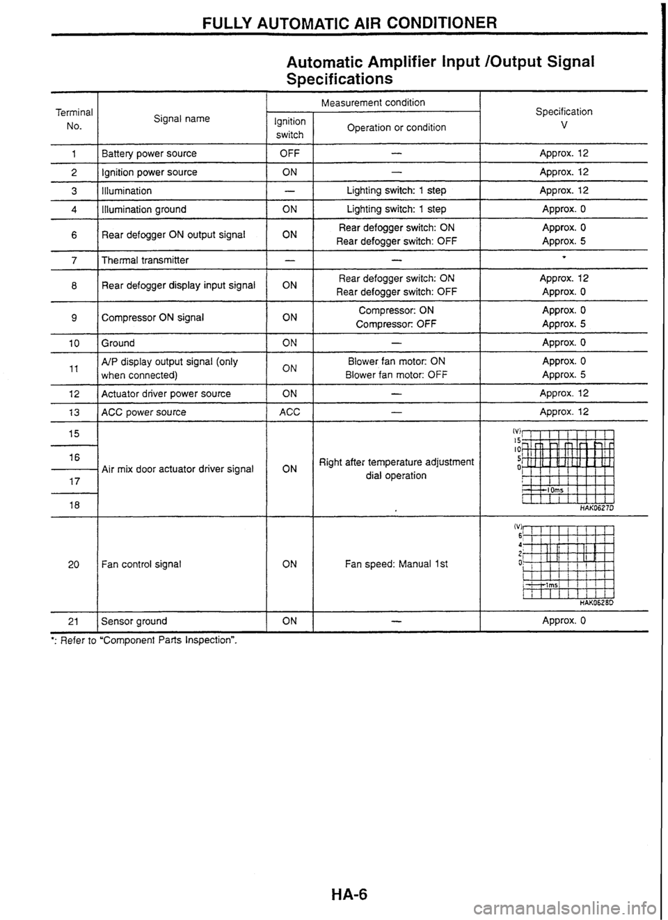
FULLY AUTOMATIC AIR CONDITIONER
Automatic Amplifier Input /Output Signal
Specifications
Measurement condition I Terminal
No. Specification
v Signal
name
Ignition
I Operation or condition
switch
OFF
I - I Approx. 12
Battery
power source
Ignition power source
lllumination
ON
I - I Approx. 12
- I Lighting switch: 1 step 1 Approx. 12
ON r Lighting switch: 1 step I Approx. o
6 1 Rear defogger ON output signal Rear
defogger switch: ON
Rear defogger switch: OFF 1
Approx. 0
Approx.
5
Rear defogger switch: ON
Rear defogger switch: OFF
1
7
Approx. 12
Approx. 0
Thermal transmitter 8 1 Rear defogger
display input signal
Compressor: ON
Compressor:
OFF
Approx. 0
Approx.
5 Compressor ON signal
ON
-I-- - - - I Approx. 0 10 1 Ground
AfP display output signal (only
when connected) Blower
fan motor: ON
Blower fan motor:
OFF
Approx. 0
Approx.
5
12 1 Actuator driver power source
ON I - 1 Approx. 12
1 3 1 ACC power source ACC I - I Approx. 12
Right after temperature adjustment
dial operation
Air mix
door actuator driver signal
Fan control signal
Fan speed: Manual
1st
ON I - I Approx. 0
21
': Refer to "Component
Parts Inspectionn.
Sensor ground
Page 153 of 230

FULLY AUTOMATIC AIR CONDITIONER
Automatic Amplifier Input /Output Signal
Terminal
No. Measurement condition
Specification V Signal name
Ignition
switch Operation
or condition
Right after mode switch (air outlet switch) operation
I
Mode door actuator driver signal
Right after
FRE switch or REC
switch operation 24
I
26 I Ambient sensor
lntake door actuator driver signal
Approx.
0
Approx. 5
A/P ON output (only when con-
'' / nected) Blower fan
motor: ON
Blower fan motor: OFF
Right after mode switch (air outlet
switch) operation
Mode door actuator driver signal
Right after
FRE switch or REC
switch operation -1 lntake door actuator driver signal
33 1 In-vehicle sensor
34 I Sunload sensor
35 1 lntake air temperature sensor
Right after FRE switch or REC
switch operation
36
*: Refer to "Component Parts Inspection".
lntake door actuator driver signal
Page 154 of 230

FULLY AUTOMATIC AIR CONDITIONER
Performance Test
PROCEDURE
Connect the manifold gauge to the vehicle side cooler cycle (service valve).
Attach a psychrometer to the recirculation air inlet port of the blower and cooling unit (below the glove box);
and attach a dry-bulb thermometer to the right side of the center ventilator grille.
Start and
warm up the engine.
After warming up the engine, check that the engine speed has reached the standard idle speed.
After pressing the AUTO switch, operate the fan switch, mode switch (air outlet switch),
REG switch, tem-
perature adjustment dial and switch; and satisfy the following conditions.
Fan speed: 4th
Air inlet: Recirculation
Air outlet: Ventilator (VENT)
Temperature setting:
18°C
Completely open the hood and all door windows, and close all doors.
Maintain these conditions until the cooler cycle stabilizes. (Approx.
10 minutes)
Maintain the engine speed at idle.
Measure the recirculation inlet temperature and humidity, outlet temperature, and cooler cycle high- and
low-pressures. Compare and judge the values with the "AMBIENT AIR TEMPERATURE AND PRESSURE
CHARACTERISTICS and "INTAKE AIR TEMPERATURE AND DISCHARGE AIR TEMPERATURE CHAR-
ACTERISTICS.
Page 155 of 230

FULLY AUTOMATIC AIR CONDITIONER
Performance Test (Cont'd)
INTAKE AIR TEMPERATURE AND DISCHARGE AIR TEMPERATURE CHARACTERISTICS
Intake air temperature .-
.AMBIENT AIR TEMPERATURE AND PRESSURE CHARACTERISTICS
Ambient temperature ---------t
HAK0660D
Page 156 of 230

FULLY AUTOMATIC AIR CONDITIONER
Trouble Diagnosis
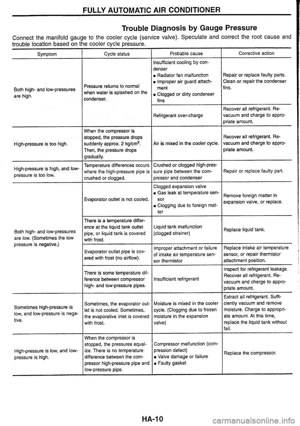
by Gauge Pressure
Connect the manifold gauge to the cooler cycle (service valve). Speculate and correct the root cause and
trouble location based on the cooler cycle pressure.
Probable cause
lnsufficient cooling
by con-
denser
Radiator fan malfunction
lmproper air guard attach-
ment
Clogged or dirty condenser
fins Corrective action
Symptom Cycle status
Repair or replace faulty parts.
Clean or repair the condenser
Pressure retums to normal
when water is splashed on the
condenser. fins.
Both high- and low-pressures
are high.
Recover all refrigerant. Re-
vacuum and charge to appro-
priate amount.
Refrigerant
over-charge
When the compressor is
stopped, the pressure drops
suddenly approx.
2 kg/cm2.
Then, the pressure drops
gradually. Recover
all refrigerant. Re-
vacuum and charge to appro-
priate amount.
Air is mixed
in the cooler cycle.
High-pressure is too high.
Temperature differences occurs
where the high-pressure pipe is
crushed or clogged. Crushed
or clogged high-pres-
sure pipe between the com-
pressor and condenser
High-pressure
is high, and
low-
pressure is too low. Repair or replace
faulty part.
Evaporator outlet is not cooled. Clogged
expansion valve
Gas leak at temperature sen-
sor
Clogging due to foreign mat-
ter
There
is a temperature differ-
ence at the liquid tank outlet
pipe, or liquid tank is covered
with frost. Remove
foreign matter in
expansion valve, or replace.
Liquid tank malfunction
(clogged strainer) Replace
liquid tank.
Both high- and low-pressures
are low. (Sometimes the low
pressure is negative.)
lmproper attachment or failure
of intake air temperature sen-
sor thermistor Replace
intake air temperature
sensor, or repair
thermistor
attachment position.
Evaporator
outlet pipe is cov-
ered with frost (no airflow).
I Inspect for refrigerant leakage.
There is some temperature dif-
ference between compressor
high- and low-pressure pipes. Recover
all refrigerant.
Re-
lnsufficient refrigerant vacuum and charge to appro-
priate amount.
Extract all refrigerant. Suff
i-
ciently vacuum and remove
moisture. Charge to appropri-
ate amount. At this time,
replace the liquid tank without
fail.
Sometimes, the evaporator out-
let is not cooled. Sometimes,
the evaporative inlet is covered
with frost. Moisture
is mixed in the cooler
cycle. (Clogging due to frozen
moisture in the expansion
valve)
Sometimes
high-pressure is
low, and low-pressure is nega-
tive.
When the compressor is
stopped, the pressures equal-
ize. There is no temperature
difference between the com-
pressor high-pressure pipe and
low-pressure pipe. Compressor
malfunction
(com-
I
pression defect)
Valve damage or failure
Faulty gasket Replace
the compressor.
High-pressure
is low, and
low-
pressure
is high.
HA-I 0
Page 157 of 230

FULLY AUTOMATIC AIR CONDITIONER
Trouble Diagnosis by Self-diagnosis Function
There are 5 steps in the self-diagnosis: to check for any sensor failure, and to check that a given control sig-
nal is transmitted to each output device.
Diagnosis
content
- - -
Diagnostic
item
i Step I I Step 2 - - - - - - - --
Each sensor check
Indicator lamp check
Display segments Ambient sensor
0 Indicator lamp In-vehicle sensor
lntake air tempera-
ture sensor
Sunload sensor Step
3
Each
actuator check
and reset check display for each
sen-
lntake door actuator
Air mix door actua-
tor Mode door actuator
lntake door actuator
Air mix door actua-
tor
Mode door actuator
Blower fan motor
Compressor
Air purifier (only
when connected)
Ambient sensor
In-vehicle sensor
lntake air tempera-
ture sensor
SELF-DIAGNOSIS OPERATION PROCEDURE R8
Switching to self-diagnosis mode
Turn the temperature adjustment dial all the way to the left.
Start the engine with the ignition switch from OFF position. Within 10 seconds, press and hold the OFF
switch for more than approx. 5 seconds, to start the self-diagnosis step 1.
Self-diagnosis completion EL
a Turn the ignition switch OFF.
Turn the AUTO switch ON.
Switching between self-diagnosis steps
Use the temperature adjustment dial to switch between self-diagnosis steps 1 to 5.
Temperature adjustment dial (turn clockwise): Step
1-5
Temperature adjustment dial (turn counterclockwise): Step
5- 1
a Refer to "SELF-DIAGNOSIS DISPLAY ITEM" for the diagnosis contents of each step.
Page 158 of 230

FULLY AUTOMATIC AIR CONDITIONER
Trouble Diagnosis
by Self-diagnosis Function
(Cont'd)
Step 3 AUTO SW: ON +
I
Step 1
(CW) Tum the temperature (CCW) Turn the temperature
adjustment dial. adjustment dial. I
IGN SW: OFF
AUTO SW: ON *
T
I Step 4 I AUTO SW: ON *
4 (CW) Turn the temperature (CCW) Turn the temperature
adjustment dial. adjustment dial. I
Step 2 IGN SW: OFF
AUTO SW: ON *
I
CW: Clockwise I CCW: Counterclockwise
Step 5 Detected temperature d~splay for each sensor IGN SW: OFF AUTO SW: ON
C : Each switch indicator lamp HAK0725D
SELF-DIAGNOSIS DISPLAY ITEM
Step 1 - Display segments and indicator lamp check
Check the controller switch indicator lamp and display segments.
Normal: The switch indicator lamp and display segments are illu-
minated.
Abnormal: Malfunctioning area will not be illuminated.
lllum~nated when a short- (T"e last digir ") circuit is detected.
the display code
the corresponding codes
Step 2 - Each sensor check
Display shows "2 in the step 2 mode, and then shows the judge-
ment result.
Check the data of each sensor inputted into the automatic ampli-
fier.
Normal: Display shows
"20.
Abnormal: The last digit of the display code flashes for a malfunc-
tioning sensor. At this time, if a short-circuit
is detected,
"AUTO is displayed. Furthermore, when there are more
than one malfunctioning sensor, the corresponding dis-
play codes flash twice starting with the smaller code.
The sunload sensor will judge an abnormality when there is
insufficient lighting (less than 5,000 lx) such as while being
placed indoor or during the evening.
Page 159 of 230

FULLY AUTOMATIC AIR CONDITIONER
Trouble Diagnosis by Self-diagnosis Function
(Cont'd)
Display code for malfunctioning sensor and identifying condition for automatic amplifier
I
The last digit of
Abnormal flashes for is detected.
Display code
21
22
24
25
a malfunctioning ( actuator terminal. I
When more than one
actuator terminal
are malfunctron~ng.
Ihe corresponding codes
flash twice starting
with the smaller code.
Sensor
Ambient sensor in-vehicle sensor
intake air temperature sensor
Sunload
sensor
Flashes twice
HAK0727C
Actuator display code
Identifying condition for automatic amplifier
Step 3 - Each actuator check and reset
Open circuit
Less than
41 .9"C
Less than -4 1 .g°C
Less than -4 1 .9"C
Less than 4 1.8 W/m2 (36.0 kcallm2. h)
Display shows "3" for approx. 1 second in the step 3 mode, and BB
then shows the judgement result.
Transmit an output signal to the intake door actuator, mode door
actuator, and air
mix door actuator; and check each actuator.
Furthermore, the actuator can be reset by pressing the front DEF
switch at this
time.
Normal: Display shows "30". I28
Abnormal: The display code flashes for a malfunctioning actuator.
At this time, if a short-circuit is detected, "AUTO is dis-
played. Furthermore, when there are more than one
malfunctioning sensor, the corresponding display codes
flash twice starting with the smaller code.
During reset: Display flashes
"30" and front DEF switch. (Approx.
P
EL
10 seconds)
Short-circuit
More than 100°C GI
More than 100°C
More than 100°C EG
More than 1729 W/m2 (1 487 kcal/m2.h)
Faulty harness display
SD
Display code
Actuator
Actuator
Terminal No. (actuator side)
Terminal
No. (automatic
amplifier side)
Open or short-circuit failure
display
31.0 - 32.5
Air mix door
': "AUTO" is displayed for a short-circuit.
33.0 - 34.5
Mode door
Air mix door actuator
35.0 - 36.5
Intake door
1
15
31.0
Mode door actuator
2
16
31.5
1
22
33.0
Intake door actuator
1
24
35.0
5
17
32.0 2
30
33.5
6
18
32.5 2
32
35.5
5
29
34.0
6
23
34.5
5
31
36.0 6
36
36.5
Page 160 of 230

FULLY AUTOMATIC AIR CONDITIONER
Trouble Diagnosis
by Self-diagnosis Function -
When '32.5" 1s d~splayed d~rlng self-diagnos~s step 3 I I I (Cont'd)
Au;omafc amplifier
Actuator driver
powe: supply
Air mix driver
1
Air mix driver 2
Air mix driver 3
Air mix driver 4
1 1 Air mix door actuator 1
circuit
I I'
When a open-circuit failure is displayed for all four terminals of
each actuator, there is a possibility of a disconnected
connector, or broken harness of the actuator driver power
SOU rce.
The self-diagnosis cannot detect short-circuit between actua-
tor driver signals, but the actuators will vibrate when actuated.
Step 4 - Each output device check
Display shows "41" in the step 4 mode. When the DEF switch is
pushed it switches from
42-343+44+45-+46-,41. As indicated in
the following table, the automatic amplifier forcefully outputs to
each actuator, blower fan motor, and compressor in response
to
the display code. Confirm and check each output operation status
by observing, listening to the operating sound, placing hand at the
air outlet, or using other methods.
The operation status of each actuator, blower fan motor, and
1
compressor cannot be confirmed on the display.
Display code for output device and status
Display code
Output device / 11 1 42 1 43 I I I
Mode door
Intake door
Air mix door
Blower fan motor
Compressor
Air purifier (only when connected) VENT I B/L FOOT
Ambient
Recirculation
Full cold
BIL
Open 50%
61 0/e 35%
ON
ON
The blower fan motor revolution is controlled by the duty ratio
signal outputted from the automatic amplifier. (For duty ratio,
refer to "Blower Fan Motor System Check" on page
HA-15.)
Step 5 - Detected temperature display for each sensor
Display shows "5" in the step 5 mode. Every time the DEF switch
is pushed, the detected sensor temperature is displayed in
0.5"C
increments.
D/F
Ambient
Recirculation
Full cold
OFF
OFF
f' 7 Sensor display switches every tlme 2 )- z -2 - - ' the front DEF rwttch is pressed. C
X In al - - t 0 - D
A1 E ? < -
DEF
Ambient 20% ambient
Open
50% Full hot
61Yo 75%
ON
ON
Full hot
1 00% 61 %
ON
ON OFF
OFF ON
ON