change time NISSAN GT-R 1998 Service Manual
[x] Cancel search | Manufacturer: NISSAN, Model Year: 1998, Model line: GT-R, Model: NISSAN GT-R 1998Pages: 230, PDF Size: 12.66 MB
Page 2 of 230

NISSAN
MODEL R34 SERIES
FOREWORD
This Sewice Manual contains infor-
mation concerning necessary ser-
vice procedures and relevant data
for the model
R34 series.
All information, illustrations and
specifications contained in this Ser-
vice Manual are based on the latest
product information available at the
time of publication. If your NISSAN
model differs from the specifications
contained in this
Sewice Manual,
consult your NISSAN distributor for
information.
The right is resewed to make
changes in specifications and meth-
ods at any time without notice.
QUICK REFERENCE INDEX I
0 1998 KISSAN MOTOR CO., LTD. Printed in Japan
A11 rights reserved. No part of this Service Manual may be reproduced or stored in a retrieval system, or transmitted in any form, or by any means, electronic, mechanical, photocopying, recording or otherwise, without the prior written permission of Nissan Motor Company Ltd.. Tokyo, Japan.
Page 31 of 230

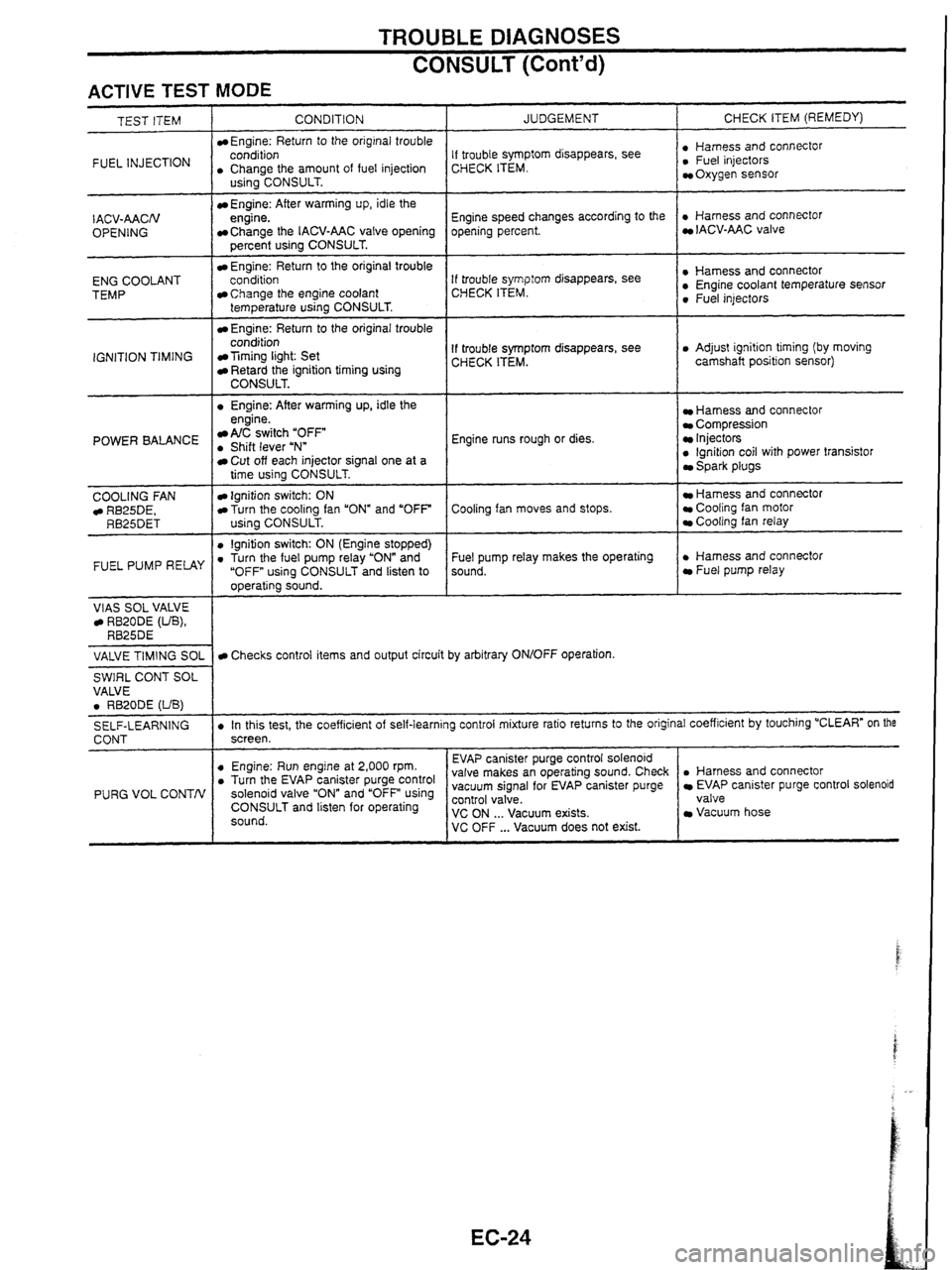
TROUBLE DIAGNOSES
CONSULT (Cont'd)
ACTIVE TEST MODE
INJECTION I . CCohArthe amount of fuel injection
TEST ITEM
CONDITION
Engine: Return
to the original trouble
- I . Engine: After warming up, idle the
IACV-AACN
OPENING
ENG COOLANT
TEMP
IGNITION TIMING
US~~~CONSULT.
Engine: After warming up, idle the
engine.
Change the IACV-AAC valve opening
percent using CONSULT.
Engine: Return to the original trouble
conditioo
Change the engine coolant
temperature using CONSULT.
Engine: Return to the original trouble
condition
Timing light: Set Retard the ignition timing using CONSULT.
POWER BALANCE engine. A/C switch "OFF . Shift lever uNn
COOLING
FAN RB25DE, RB25DET
FUEL PUMP RELAY
VlAS SOL VALVE RB20DE (UB), RB25DE
JUDGEMENT
Cut off each injector signal one at a
time using CONSULT.
Ignition switch: ON Turn the cooling fan "ON" and "OFF
using CONSULT.
0 lgnition switch: ON (Engine stopped) . Turn the fuel pump relay "ON" and
"OFF using CONSULT and listen to
operating sound. CHECK
ITEM (REMEDY)
If trouble symptom disappears, see
CHECK ITEM. : ~,"~~,,,~scOnnectOr Oxygen sensor
Engine speed changes according to the
opening percent.
. Harness and connector IACV-AAC valve
If trouble
symp:orn disappears, see
CHECK ITEM. : Sensor 0 Fuel injectors
If trouble symptom disappears, see
CHECK ITEM. 0 Adjust ignition timing (by moving
camshaft position sensor)
Engine runs rough or dies.
Harness and connector Compression Injectors 0 lgnition coil with power transistor Spark plugs
Cooling fan moves and stops.
Hamess and connector Cooling fan motor Cooling fan relay
Fuel pump relay makes the operating
sound.
. Harness and connector Fuel pump relay
VALVE
TIMING
SOL
SWIRL CONT SOL
VALVE
0 RB20DE (UB)
SELF-LEARNING
CONT
PURG VOL CONTN
Checks control items and output circuit by arbitrary ON/OFF operation.
. In this test, the coefficient of self-learning control mixture ratio returns to the original coefficient by touching "CLEAR" on the
screen.
. Harness and connector EVAP canister purge control solenoid
valve
Vacuum hose
0 Engine: Run engine at 2,000 rpm. . Turn the EV~P canister purge control solenoid valve and using CONSULT and listen for operating
sound. EVAP
canister purge control solenoid
valve makes an operating sound. Check
vacuum signal for EVAP canister purge ~~~~~~a'cuum exists. VC OFF ... Vacuum does not exist.
Page 34 of 230

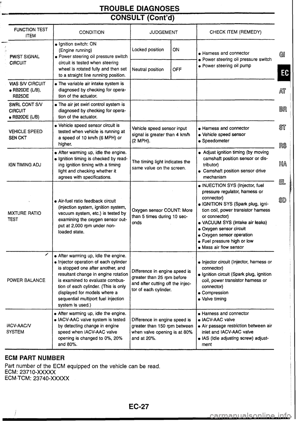
TROUBLE DIAGNOSES
CONSULT (Cont'd) --
CHECK ITEM (REMEDY)
FUNCTION TEST
ITEM CONDITION
JUDGEMENT
-
PWIST SIGNAL Locked position
Neutral position
Ignition
switch: ON
(Engine running)
Power steering oil pressure switch
circuit is tested when steering
wheel is rotated fully and then set
to a straight line running position. ON
OFF Harness and connector
Power steering oil pressure switch GO
CIRCUIT a Power steering oil pump
I VlAS SN CIRCUIT
0 RB20DE (UB),
RB25DE
The variable air intake system is
diagnosed by checking for opera-
tion of the actuator.
-
SWRL CONT SN
CIRCUIT
0 RB20DE (UB)
The air jet swirl control system is
diagnosed by checking for opera-
tion of the actuator.
-- -- -
a Vehicle speed sensor circuit is
tested when vehicle
is running at
a speed of 10 km/h (6 MPH) or
higher.
After warming up, idle the engine.
Ignition timing is checked by read-
ing ignition timing with a timing
light and checking whether it
agrees with specifications.
Harness and connector 877
Vehicle speed sensor
Vehicle
speed sensor input
signal is greater than 4 krnlh
(2 MPH).
VEHICLE SPEED
SEN CKT Speedometer
RS
Adjust ignition timing (by moving
camshaft position sensor or dis-
tributor)
HA
Camshaft position sensor drive
The
timing light indicates the
same value on the screen.
IGN
TIMING
ADJ
mechanism
la INJECTION SYS (Injector, fuel
pressure regulator, harness or
connector)
IGNITION SYS (Spark plug, igni-
tion coil, power transistor harness
or connector)
VACUUM SYS (Intake air leaks)
Oxygen sensor circuit
Oxygen sensor operation
Fuel pressure high or low
Mass air flow sensor
Air-fuel ratio feedback circuit
(injection system, ignition system,
vacuum system, etc.) is tested by
examining the oxygen sensor out-
put at 2,000
rpm under non-
loaded state. Oxygen sensor COUNT
More
than
5 times during 10 sec-
onds
MIXTURE
RATIO
TEST
- -- /
POWER BALANCE
Injector circuit (Injector, harness or
connector)
Ignition circuit (Spark plug, ignition
coil, power transistor harness or
connector)
Compression
Valve timing
After warming up, idle the engine.
Injector operation of each cylinder
is stopped one after another, and
resultant change in engine rotation
is examined to evaluate combus-
tion of each cylinder. (This is only
displayed for models where a
sequential
multipart fuel injection
system is used.)
D After warming up, idle the engine.
D IACV-AAC valve system is tested
by detecting change in engine
speed when IACV-AAC valve
opening is changed to
0%, 20%
and 80%. Difference
in engine speed is
greater than 25 rpm before
and after cutting off the injec-
tor of each cylinder.
Harness and connector
IACV-AAC valve
Air passage restriction between air
inlet and IACV-AAC valve
IAS (Idle adjusting screw) adjust-
ment
Difference
in engine speed is
greater than 150
rpm
between
when valve opening is at 80%
and at 20%.
IACV-AACN
SYSTEM
ECM PART NUMBER
Part number of the ECM equipped on the vehicle
can be read.
ECM: 2371 0-XXXXX
ECM-TCM: 23740-XXXXX
Page 37 of 230

TROUBLE DIAGNOSES
Symptom Matrix Chart (Cont'd)
Sensor-related problems I Symptom characteristics and ins~ection hints
Open Engine
will not start when either REF signal circuit or POS signal circuit is open.
Neither fuel system nor ignition system outputs control signals.
Crankshaft position sensor
(POS, REF) Instanta-
neous break Symptoms
vary with the break time and the vehicle's driving conditions. Light
shock or surging will occur while the vehicle is being driven, and the engine will
stall at idle speed.
Ring gear crankshaft position
sensor
[RB20DE
(UB)]
Signal
Mass air flow sensor Open
Open
High output
Low output I Aidfuel
ratio becomes lean. Dirty hot wire or air entering the system could be the
cause. No
airfluel ratio compensation
is carried out during lean bum status. Drivability
may be affected.
Enters fail-safe mode. Driving under
2,400 rpm is allowed.
Airlfuel
ratio becomes rich. Black smoke may be noted. Poor contact at the
ground could be the cause.
Engine coolant temperature sen-
sor Open
Open
Opedshort
High resis-
tance
Low resis-
tance
Opedshort
Heated oxygen sensor
I
Airlfuel ratio becomes over-rich.
Same symptom as when signal wire is open.
Enters fail-safe mode. Malfunction indicator lamp comes ON. Ordinary driving is
allowed. Problems tend to occur when engine is cold or engine coolant tempera-
ture
is high.
Detects low engine coolant temperature. Problems tend to occur after engine
warm-up.
Detects high engine coolant temperature. Problems tend to occur when engine is
cold.
Base
aidfuel ratio is used.
lgnition timing is retarded within the knock control range. Lack of power may be
OpedShort
I noted.
Knock sensor lgnition
timing is retarded within the knock control range. Lack of power may be
High
Output
(noted.
Low output
1 lgnition timing may not be retarded when knock is detected.
Vehicle speed sensor
Throttle position sensor
Opedshort
Opedshort
Unstable out-
put
Poor adjust-
ment
Open
Turbo pressure sensor
(TE) Fuel
cut time becomes-shorter, or no fuel cut is observed.
Base idle speed is used. Fuel injection is not increased during acceleration.
AIT shift point changes for AfF vehicles.
Unnecessary cut-in fuel injection could be the cause. Poor contact at the ground
or control unit could be the cause.
ldle judgment is "OFF while idling. Condition returns
normal by turning the igni-
tion switch ON and OFF repeatedly.
Turbo pressure is judged zero. No remarkable malfunction will be detected.
Refrigerant pressure is judged high. ldle speed remains high while the air condi-
tioner is ON.
Refrigerant pressure sensor
Short Refrigerant pressure
is judged low. ldle speed remains low while the air condi-
tioner is ON.
lgnition switch (IGN)
lgnition switch (START)
Air conditioner switch Open
Engine
will not start because neither fuel system nor ignition system outputs con-
trol signals.
Engine starts in normal condition. Engine may not start when temperature is
extremefy
low.
Air conditioner will not operate. No other malfunction will be noted.
Park/neutral
position switch is judged "OFF. Target engine speed for cold engine
in
N or P position is reduced.
ParWneutral position switch is judged
"0N"I Fast Jdle is effective when the engine
is cold and the gear is in other than N and P posrtlons. Vehrcle excessrvely
creeps.
Open
Open
Parklneutral
position
switch
Short
Power steering oil pressure
switch Open
Engine may
stall when the steering wheel is turned while the vehicle is standstill
and the accelerator pedal is lightly pressed, or when the steering wheel is turned
Electrical load switch Short
Open
Open/short
Multiplex communication line
- -- during deceleration. '
Power steering switch is judged 'ON." Value will be compensated constantly.
Idle speed drops so that the engine can stall when electrical load is applied.
Torque reduction control is not performed. Therefore,
shift shock becomes
greater.
- -- -- -- -- Engine will not start because neither fuel system nor ignition system outputs con-
trol signals.
Open
Control unit power supply
- -- - - --- - - - - - O~edshort I Same symptoms as when sensor harness is open.
Sensor ground -- - Poor contact
Water intru-
sion - -- - - - - - -- -- In case of poor contact, the connector fitting may be loose. In case of water
intrusion, the engine stalls and become inoperative for a while. The engine may restart soon in some cases.
Control unit
and connector
Page 119 of 230

TCSIABS SYSTEM
CONSULT
for Throttle Control Unit Control
bJ SELECT DIAG MODE
SELF-DIAG RESULTS & I
DATA MONITOR 1
ACTIVE TEST I
ECU PART NUMBER I
I P?j SELECTTEST ITEM
I THROTIIEZ OPENING a
I THROTTLE MOTOR I
1 THROTLE MOTOR RLY 1
w ACTIVE TEST
THRTL2 OPENlNG 0.00" ---------- ---------- MONITOR ==========
THRL2 OPENING 0.00"
THMOTORDUTY 20.0°/0
System (Cont'd)
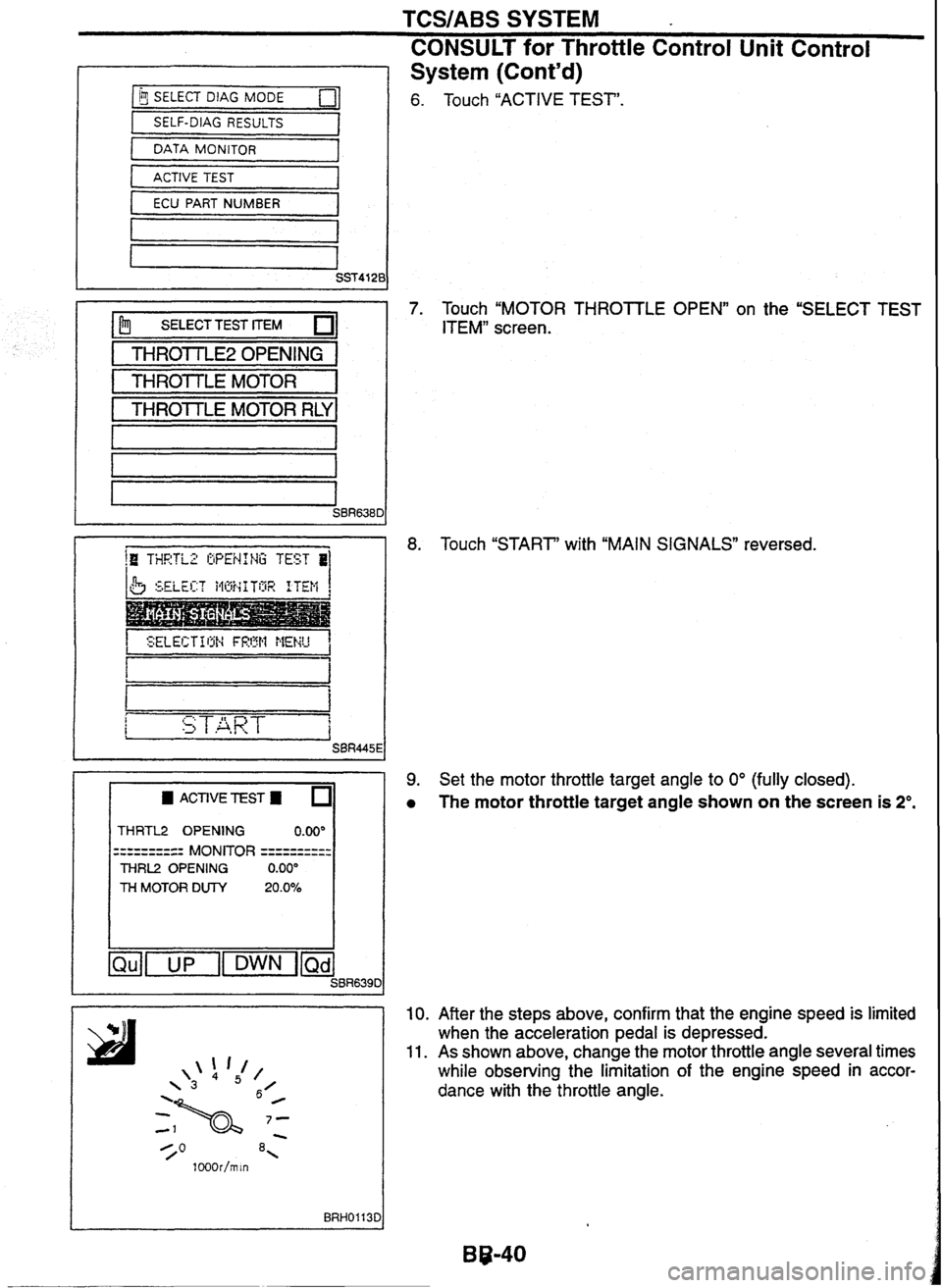
Touch "ACTIVE TEST".
Touch
"MOTOR THROSTLE OPEN" on the "SELECT TEST
ITEMn screen.
Touch "START' with "MAIN SIGNALS" reversed.
Set the motor throttle target angle to
0° (fully closed).
The motor throttle target angle shown on the screen is 2".
After the steps above, confirm that the engine speed is limited
when the acceleration pedal is depressed.
As shown above, change the motor throttle angle several times
while observing the limitation of the engine speed in accor-
dance with the throttle angle.
Page 129 of 230

ELECTRIC SUPER HICAS
Trouble
Diagnosis with CONSULT (Cont'd)
SELF-DIAGNOSTIC RESULTS MOI -- - - -
Diagnostic item
Diagnostic item is detected when ...
Vehicle speed signal changes rapidly during
running.
I Remarks
VEHICLE SPEED SEN
[SIGNAL
TURN](.b)
I This code appears also when
engine is idling at
1,500 rpm
or faster for more than 10
, seconds; in this case, it does
not indicate abnormality.
Vehicle speed signal is not sensed for more
than
10 seconds while the vehicle is running
at
1,500 rpm of engine speed.
CODE
54
STEERING
ANGLE SEN
[NO ANG
SIG](.a) Steering angle does not change for a while
when vehicle is running at 60
km,h or faster.
Steering angle from neutral position is kept at
60" degrees or more for a certain time when
vehicle is running
at 50 km/h or faster.
Steering angle from neutral position is kept at
30" degrees or more while vehicle travels a
certain distance.
STEERING
ANGLE SEN
[ANG SIG
FIX](.e)
STEERING ANGLE
SEN
[ANG
F1X3O0](-g)
STEERING ANGLE SEN
[NO NEUT
SIG](.b)
No neutral signal (ON signal) is sensed while
vehicle travels a certain distance.
No neutral signal (ON signal) is sensed while
steering wheel is turned more than
360'.
No neutral signal (OFF signal) is sensed while
steering wheel is turned more than
50"
degrees.
STEERING ANGLE
SEN
[NEU SIG
OFF](.c)
STEERING
ANGLE SEN
[NEUT SIG
ON](.d) - - --
a When steering wheel
is turned 360" after the
detection of neutral signal, the neutral signal is
sensed for
a certain period of time.
STEERING ANGLE
SEN
[OFFSET
NEUTJ(.f)
For a certain
period of time, input signal from
main sensor shows abnormality against sensor
power supply voltage.
a When input signal from main sefisor shows
2.5+1 V, input signal from sub-sensor shows
abnormality against sensor power supply volt-
age for a certain period of time.
RR
ST ANGLE SENSOR
[MAIN
SIGNAL](.a)
RR ST ANGLE SENSOR
[SUB
SIGNALJ(.b)
- -
Input signals from main sensor and sub-sen-
sor show more than a certain amount of differ-
ence from each other.
The voltage is higher or lower than the stan-
dard value.
RR
ST ANGLE SENSOR
[OFFSET SIG](-C)
RR ST ANGLE SENSOR
[ABNORMAL
VOL](.d)
r
a Engine speed shows an abnormally low value
for a certain period of time when vehicle is
running at
2 krnlh or faster.
ENG
REV SIGNAL
[ABNORMAL SIGNAL]
a When HlCAS motor relay is ON, motor power
supply voltage shows an abnormally lower
value than ignition power supply voltage.
When control unit keeps motor power OFF, the
motor power voltage shows a non-zero value
for a certain period of time.
MOTOR VOLTAGE
[LOW VOLTAGE](-a)
MOTOR VOLTAGE
[BAD
OBSTRCT](.b)
When a motor current is more than IOA, the
actual output of the motor shows an abnor-
mally low value for a certain period of time.
MOTOR
OUTPUT
[ABNORML
SIG](.a)
- -
MOTOR OUTPUT
[REV CURRENTJ(-C) When motor output is kept ON, a reverse cur-
rent is flowing.
Page 130 of 230

VEHICLE SP NISSAN GT-R 1998 Service Manual
ELECTRIC SUPER HlCAS
Trouble Diagnosis
with CONSULT (Contd)
Diagnostic item
MOTOR OUTPUT
[NO
CURRENTJ(.d)
MOTOR OUTPUT
[OVERCU
RRENTl(.e)
MOTOR OUTPUT
[MOTOR
LOCK](.
b)
VEHICLE SP](/img/5/57354/w960_57354-129.png)
ELECTRIC SUPER HlCAS
Trouble Diagnosis
with CONSULT (Cont'd)
Diagnostic item
MOTOR OUTPUT
[NO
CURRENTJ(.d)
MOTOR OUTPUT
[OVERCU
RRENTl(.e)
MOTOR OUTPUT
[MOTOR
LOCK](.
b)
VEHICLE SPEED SEN
[RAPD SIGN CHANGE21
VEHICLE SPEED SEN
[NO
SIGNAU]
VEHICLE SPEED SEN
[NO SIGNAL31
CONTROL UNIT
[ABNORMAL
1-61
Diagnostic item is detected when ... I Remarks
When motor output is kept OFF, a current is
flowing.
When motor output is kept ON, an overcurrent
is flowing.
Signal from rear steering angle sensor does
not change for a certain period of time while a
motor current of
17A or more is flowing.
When vehicle is running, vehicle speed signal
is not sensed for a certain period of time after
it has changed rapidly.
"VEHICLE SPEED SEN [RPD SIG CHG2J"
has occurred previously, and vehicle speed
signal is not sensed for a certain period of
time.
I
'VEHICLE SPEED SEN [RPD SIG CHG2]" I I
has not occurred previously, and vehicle
speed signal is not sensed for a certain period
of time while the vehicle is running at
1,500
rpm of engine speed.
Control unit is malfunctioning.
Page 141 of 230

TROUBLE DIAGNOSES - Supplemental Restraint System (SRS)
Trouble Diagnoses with CONSULT (Cont'd)
TROUBLE DIAGNOSIS RECORD
If a malfunction has occurred but is not recorded on seif-diagnosis,
it may be caused by some past malfunction. In such a case, past
malfunctions can be found
by selecting "TROUBLE DlAG
RECORD" in Diagnosis mode.
The "TROUBLE DlAG RECORD" can be selected for SRS air
bag system only.
Trouble Diagnoses without CONSULT
SRS AIR BAG SYSTEM
Self-diagnosis
The diagnosis modes are User mode and Diagnosis mode.
Switching between the two modes is accomplished by using
ignition switch
and driver door switch.
When lamp is not flashing (indicating no malfunction) in User mode, operating the door switch cannot change
the mode to Diagnosis mode.
When no malfunction is detected in Diagnosis mode, turning the ignition switch from "OFF" to "ON" changes
the mode to User mode. SRB0395D
User mode
Turn diver door switch 'ON" and 'OFF" at least 5 times within 7 seconds after sw~tching the
No malfunction is detected. (Lamp OFF)
IGN SW: ON
ON
OFF- 7 sec.
System is malfunctioning. (Lamp flashes)
Diagnosis
mode
User mode
ON
OFF
b A k Turn driver door switch "ON" and "OFF at
least 5, times
within 7 seconds after sw~tching
the ignition "ON".
IGN SW: OFF to ON IGN SW: OFF to ON
ignition
"ON".
-
- -
0.5 see. 0.5 sec.
Air bag is deployed or all of diagnosis sensor unit, air bag power supply circuit and AIR BAG warning lamp cir-
cuit are malfunctioning. (Lamp ON)
ON
OFF
Either air bag sensor unit or AIR BAG warning lamp circuit is malfunctioning. (Lamp OFF)
IGN SW: ON
OFF + SRB0412D
The display indicating a malfunction (flashes) keeps operation
until reset. If, however, the malfunction is a low battery volt-
age (less than 9V), the display changes from flashing to nor-
mal operation when the battery voltage has returned to normal
(more than
9V).