stop start NISSAN GT-R 1998 Service Manual
[x] Cancel search | Manufacturer: NISSAN, Model Year: 1998, Model line: GT-R, Model: NISSAN GT-R 1998Pages: 230, PDF Size: 12.66 MB
Page 24 of 230
TROUBLE DIAGNOSES
Self-diagnosis (Cont'd)
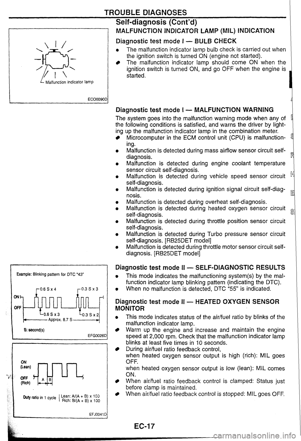
I Malfunction indicator lamp
MALFUNCTiON INDICATOR LAMP (MIL) INDICATION
Diagnostic test mode I - BULB CHECK
0 The malfunction indicator lamp bulb check is carried out when
the ignition switch is turned
ON (engine not started).
The malfunction indicator lamp should come ON when the
ignition switch is turned
ON, and go OFF when the engine is
started.
Example: Blinking pattern for DTC "43"
ONh
OFF
Approx. 8.7 S
OFF (Rich)
Duty ratio in 1 cycle 1 Lean: Al(A + B) x 100 Rich: B/(A + B) x 100
EFJ0041 C
Diagnostic test mode I - MALFUNCTION WARNING
The system goes into the malfunction warning mode when any of
the following conditions is satisfied, and warns the driver by light-
ing up the malfunction indicator lamp in the combination meter.
Microcomputer in the ECM control unit (CPU) is malfunction-
1
ing.
Malfunction is detected during mass airflow sensor circuit self-
diagnosis.
Malfunction is detected during engine coolant temperature
sensor circuit self-diagnosis.
Malfunction is detected during vehicle speed sensor circuit
self-diagnosis.
Malfunction is detected during ignition signal circuit
self-diag-
nosis.
Malfunction is detected during overheat self-diagnosis.
Malfunction is detected during heated oxygen sensor circuit
self-diagnosis.
~alfunsion is detected during throttle position sensor circuit
self-diagnosis.
Malfunction is detected during Turbo pressure sensor circuit
self-diagnosis.
[RB25DET model]
Malfunction is detected during throttle motor sensor circuit self-
diagnosis.
[RB25DET model]
Diagnostic test mode I1 - SELF-DIAGNOSTIC RESULTS
0 This mode indicates the malfunctioning system(s) by the mal-
function indicator lamp blinking pattern (indicating the DTC).
0 When no malfunction is detected, DTC "55" is indicated.
Diagnostic test mode II - HEATED OXYGEN SENSOR
MONITOR
0 This mode indicates status of the aidfuel ratio by blinks of the
malfunction indicator lamp.
Warm up the engine and increase and maintain the engine
speed at 2,000 rpm. Check that the malfunction indicator lamp
blinks at least five times in
10 seconds.
During airlfuel ratio feedback control,
when heated oxygen sensor output is high (rich): MIL goes
OFF.
when heated oxygen sensor output is low (lean):
MIL comes
ON.
When aidfuel ratio feedback control is clamped: Status just
before clamp
is maintained.
When airifuel ratio feedback control is stopped: MIL goes OFF.
Page 27 of 230
TROUBLE DIAGNOSES
CONSULT (Cont'd)
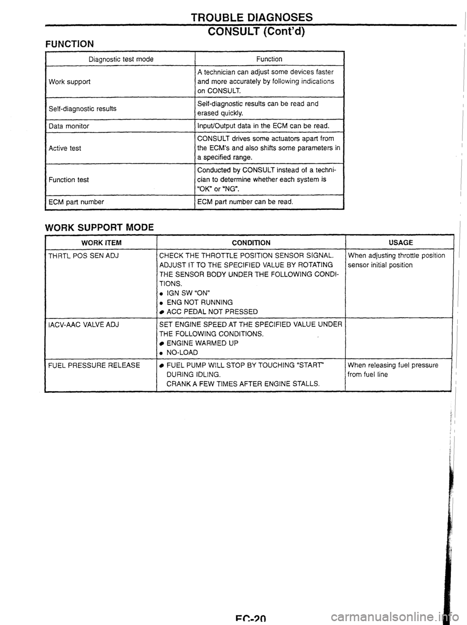
FUNCTION
Self-diagnostic results Diagnostic test mode
Work support
Self-diagnostic resuits can
be read and
erased quickly. Function
A technician can adjust some devices faster
and more accurately by following indications
on CONSULT.
Data monitor
Active test
WORK SUPPORT MODE
Input/Output data in the ECM can be read.
CONSULT drives some actuators apart from
the
ECM's and
also shifts some parameters in
a specified range.
Conducted
by CONSULT instead of a techni-
Function test
ECM part number
WORK ITEM I CONDITION I USAGE
cian to determine whether each system is
"OK" or
"NG".
ECM part number can be read.
THRTL
POS SEN ADJ CHECK THE THROTTLE POSITION SENSOR SIGNAL.
ADJUST IT TO THE SPECIFIED VALUE
BY ROTATING
THE SENSOR BODY UNDER THE FOLLOWING CONDI-
TIONS.
0 IGN SW "ONn
0 ENG NOT RUNNING When adjusting
throttle position
sensor initial position
I ACC PEDAL NOT PRESSED 1 I
IACV-AAC VALVE ADJ I SET ENGINE SPEED AT THE SPECIFIED VALUE UNDER I 1 THE FOLLOWING CONDITIONS.
ENGINE WARMED UP
When releasing fuel pressure I
from fuel line
FUEL
PRESSURE RELEASE
0 NO-LOAD
FUEL PUMP WILL STOP BY TOUCHING "START"
DURING IDLING.
CRANK A FEW TIMES AFTER ENGINE STALLS.
i J
Page 29 of 230
![NISSAN GT-R 1998 Service Manual
TROUBLE DIAGNOSES
CONSULT (Contd)
DATA MONITOR MODE
ECM input
signals
Monitored item
[Unit] Main
signals Remarks
Description
lndicates the engine speed computed
from the POS signal (l NISSAN GT-R 1998 Service Manual
TROUBLE DIAGNOSES
CONSULT (Contd)
DATA MONITOR MODE
ECM input
signals
Monitored item
[Unit] Main
signals Remarks
Description
lndicates the engine speed computed
from the POS signal (l](/img/5/57354/w960_57354-28.png)
TROUBLE DIAGNOSES
CONSULT (Cont'd)
DATA MONITOR MODE
ECM input
signals
Monitored item
[Unit] Main
signals Remarks
Description
lndicates the engine speed computed
from the POS signal (lo signal) of the
camshaft position sensor.
When the engine is stopped, a certain
value is indicated.
When the engine coolant temperature
sensor is open or short-circuited, ECM
enters fail-safe mode. The engine coolant
temperature determined by the ECM is
displayed.
The signai voltage of the mass air flow
0 sensor is displayed.
The engine coolant temperature (deter-
mined by the signal voltage of the engine
0 coolant temperature sensor) is displayed.
-
MAS AIRiFL SE [V]
The signal voltage of the oxygen sensor
is displayed.
02
SEN [V]'
0 After turning ON the ignition switch, "RICH" is displayed until air-fuel mixture
ratio feedback control begins.
When the air-fuel ratio feedback is
clamped, the value just before the clamp-
ing is displayed continuously.
MiR
F/C MNT*
[RICH/LEAN] Display of oxygen sensor signal during
air-fuel ratio feedback control:
RICH
... means the mixture became
"rich", and control is being affected
toward a leaner mixture.
LEAN
... means the mixture became
"lean", and control is being affected
toward
a rich mixture.
The vehicle speed computed from the
vehicle speed sensor signal is displayed. VHCL SPEED SE [krn/h] or [mph]
The power supply voltage of ECM is dis-
played. I BATTERY VOLT [V]
THRTL POS SEN [V] The throttle position sensor signal volt-
age is displayed.
Throttle motor sensor output voltage Approx. 4.6V THRTL POS SE2 [V] 0 RB25DET
TURBO BOOST
SENSOR
RB25DET
Turbo pressure sensor output voltage 0 Approx. 2.7V
Indicates [ON/OFF] condition from the After starting the engine, [OFF] is dis-
0 starter signal. played regardless of the starter signal.
lndicates [ON/OFF] condition from the 0 throttle position sensor signal.
-
START SIGNAL
[ON/OFF]
CLSD THUP SW
[0
N/O
FF]
0 lndicates [ON/OFF] condition of the air
conditioner switch as determined by the
air conditioner sianal. AIR COND SIG
[ON/OFF]
lndicates [ON/OFFj condition from the
parldneutral position switch signal.
PiN
POSl SW [ONIOFF)
PW/ST SIGNAL
[ONIOFF]
LOAD SIGNAL
[ON/OFF]
lndicates [ON/OFfl condition from the
electrical load signal
andlor lighting
switch.
ON ... rear defogger is operating.
OFF ... rear defogger is not operating.
NOTE: Any monitored item that does not match the vehicle being diagnosed is deleted from the display automatically. *: Models with three way catalyst.
Page 33 of 230

TROUBLE DIAGNOSES t i
CONSULT (Cont'd) i
FUNCTION TEST MODE
CHECK ITEM (REMEDY)
FUNCTION
TEST
ITEM JUDGEMENT
CONDITION
lgnition switch: ON
(Engine stopped)
Displays the results of on board
diagnostic system.
SELF-DIAG
RESULTS Objective
system
--
ignition switch: ON
(Engine stopped)
Throttle position sensor circuit is
tested when throttle is opened and
closed fully. ("IDLE POSITION" is
the test item name for the vehicles
in which idle is selected by throttle
position sensor.) Harness and connector
Throttle position sensor (Closed
throttle position)
Throttle position sensor (Closed
throttle position) adjustment
Throttle linkage
Venfy operation in DATA
MONITOR mode.
Throttle
valve:
opened OFF
ON
CLOSED THROTTLE
POSl Throttle valve:
closed
lgnition switch: ON
(Engine stopped)
Throttle position sensor circuit is
tested when throttle is opened and
closed fully.
Harness and connector
Throttle position sensor
Throttle position sensor
adjustment
Throttle linkage
Verify operation in DATA
MONITOR mode.
Range
(Throttle
valve fully opened
- Throttle valve
fully closed) More
than 3.0V THROTTLE POSl
SEN CKT
lgnition switch: ON
(Engine stopped)
Neutral position switch circuit is
tested when shift lever is
manipulated.
lgnition switch: ON
(Engine stopped)
Fuel pump circuit is tested by
checking the pulsation in fuel
pressure when fuel tube is
pinched. Out of
N/P
positions OFF
Harness
and connector
Neutral position switch
Linkage adjustment
PARWNEUT POSl SW CKT
In
N/P positions
Harness and connector
Fuel pump
Fuel pump relay
Fuel filter clogging
Fuel level
There
is pressure pulsation on
the fuel feed hose.
FUEL PUMP
CIRCUIT
--
The valve timing control system is
diagnosed by checking for
operating sound of the solenoid
valve.
lgnition switch: ON
(Engine stopped)
Cooling fan circuit is tested when
cooling fan is rotated.
VALVE
TIMING
SN
CKT
Harness and connector
Cooling fan motor
Cooling fan relay
COOLING
FAN
CIRCUIT RB25DE, RB25DET
The cooling fan rotates and
stops every
3 seconds.
lgnition switch: ON -+ START
Start signal circuit is tested when
engine is started by operating the
starter. Battery voltage and water
temperature before cranking, and
average battery voltage, mass air
flow sensor output voltage and
cranking speed during cranking
are displayed.
Harness and connector
lgnition switch
START
SIGNAL
CIRCUIT Start
signal: OFF 3 ON
Page 84 of 230
ANTI-LOCK BRAKE SYSTEM
ABS control unit connector
Terminal No.
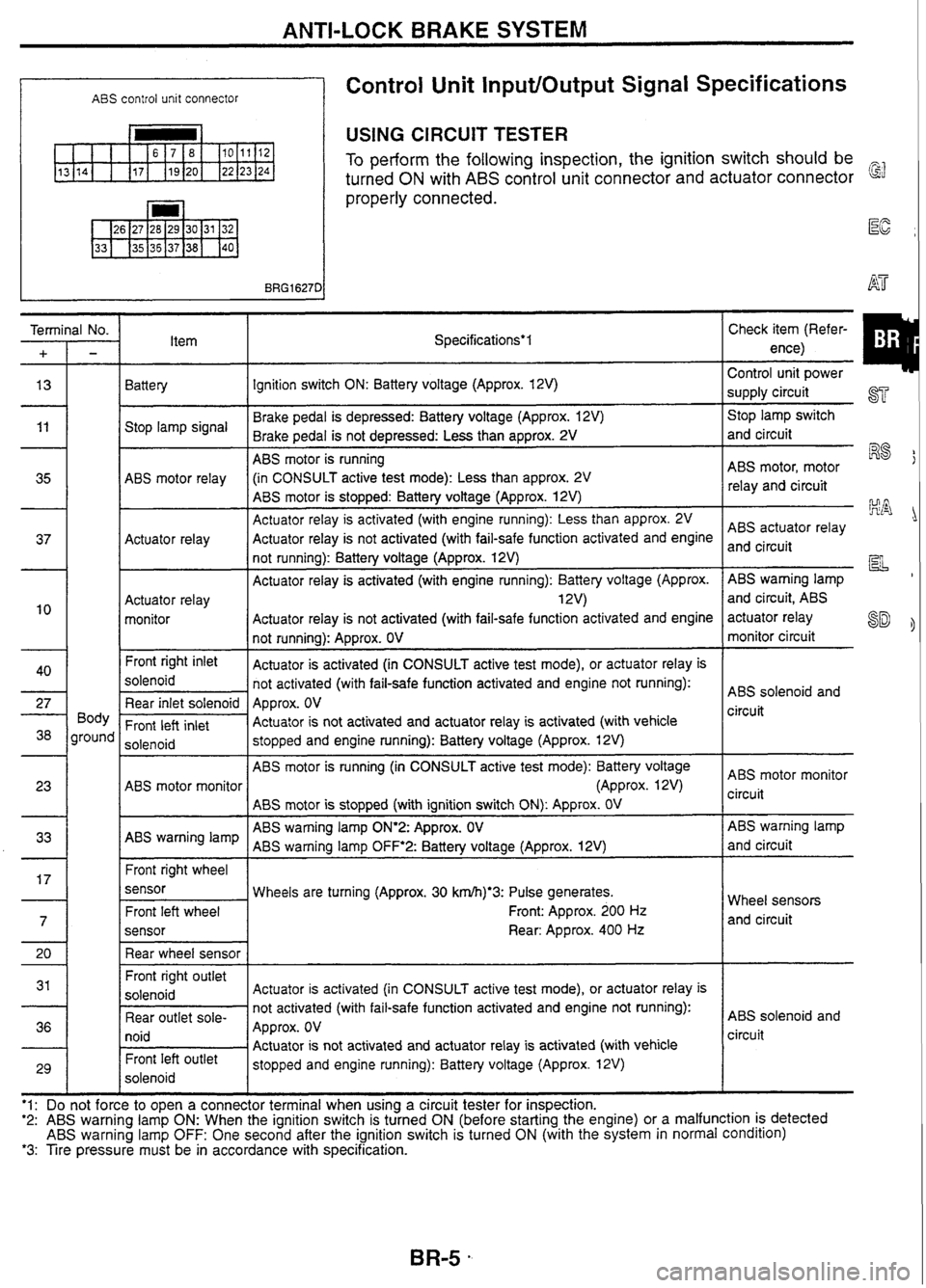
Control Unit InputlOutput Signal Specifications
USING CIRCUIT TESTER
To perform the following inspection, the ignition switch should be
turned
ON with ABS control unit connector and actuator connector
properly connected.
Item Specifications*l
Battery Ignition switch ON: Battery voltage (Approx. 12V)
Brake pedal is depressed: Battery voltage (Approx. 12V)
Stop lamp signal
Brake pedal is not depressed: Less than approx.
2V
ABS motor is running
ABS motor relay (in
CONSULT active test mode): Less than approx.
2V
ABS motor is stopped: Battery voltage (Approx.
12V)
Actuator relay is activated (with engine running): Less than approx. 2V
Actuator relay Actuator
relay is not activated (with fail-safe function activated and engine
not running): Battery voltage (Approx. 12V)
Actuator relay is activated (with engine running): Battery voltage (Approx.
Actuator relay 1 2V)
monitor Actuator
relay is not activated (with fail-safe function activated and engine
not running): Approx. OV
Front
right inlet
Actuator is activated (in CONSULT active test mode), or actuator relay is
solenoid not activated (with fail-safe function activated and engine not running):
Rear inlet solenoid Approx. OV
Front
left inlet Actuator
is not activated and actuator relay is activated (with vehicle
solenoid stopped
and engine running): Battery voltage (Approx. 12V)
ABS motor is running (in CONSULT active test mode): Battery voltage
ABS motor monitor (Approx. 12V)
ABS motor is stopped (with ignition switch
ON): Approx. OV
ABS warning lamp
ON'2:
Approx. OV
ABS warning lamp
ABS warning lamp
OFF'2:
Battery voltage (Approx. 12V)
Front right wheel
sensor Wheels are turning (Approx. 30
krn/h)*3: Pulse generates.
Front: Approx. 200
Hz
sensor
Rear: Approx. 400 Hz
Front right outlet
Actuator is activated (in CONSULT active test mode), or actuator relay is
not activated (with fail-safe function activated and engine not running):
Rear outlet
sole-
Approx. OV
I lUlU / Actuator is not activated and actuator relay is activated (with vehicle Front left Outlet stopped and engine running): Battery voltage (Approx. 12V)
solenoid
'1:e
to
tooen
a connector terminal when
using a circuit tester for inspection. Control
I
unit
power
supply circuit
ST
Stop lamp switch
and circuit
ABS motor, motor
R8
relay and circuit
ABS actuator relay
and circuit
pL
ABS warning lamp
and circuit, ABS
actuator relay
SD monitor circuit
ABS solenoid and
circuit
ABS motor monitor
circuit
ABS warning lamp
and circuit
Wheel sensors and circuit
ABS solenoid and
circuit
'2: ABS warning lamp ON: When the ignition switch is turned ON (before starting the engine) or a malfunction is detected ABS warning lamp OFF: One second after the ignition switch is turned ON (with the system in normal condition) *3: Tire pressure must be in accordance with specification.
Page 85 of 230
ANTI-LOCK BRAKE SYSTEM
Control Unit InputfOutput Signal Specifications
(Cont'd)
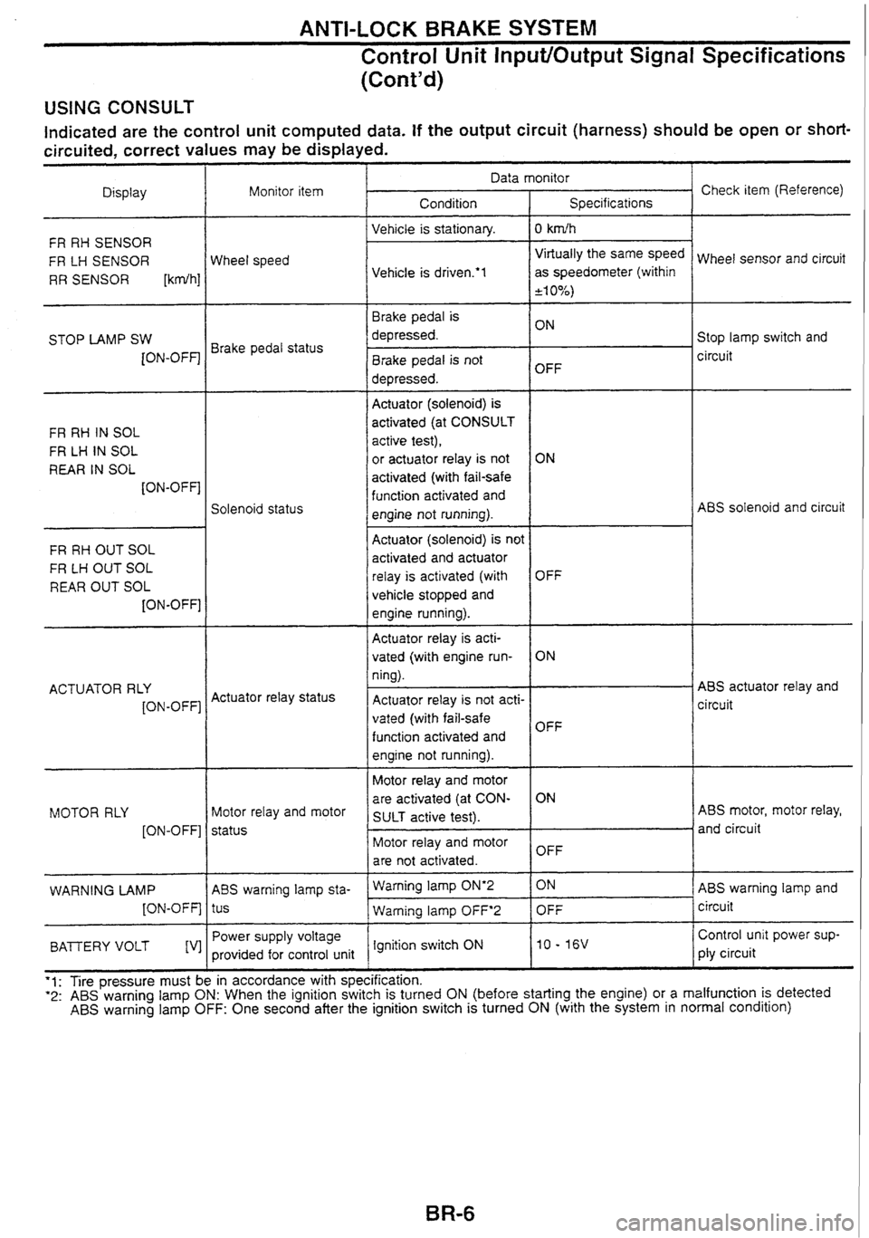
USING CONSULT
Indicated are the control unit computed data. If the output circuit (harness) should be open or short-
circuited, correct values may be displayed.
Check item (Reference)
Data monitor
Display Condition
Monitor
item
Specifications
Vehicle is stationary.
I 0 kdh
FR RH SENSOR
FR LH SENSOR
RR SENSOR
[kdh]
Virtually the same speed
as speedometer (within
+I 0%)
Wheel sensor and circuit
Wheel speed
Vehicle is
drivem'l
Brake pedal is
depressed. Stop lamp switch and
circuit
STOP
LAMP SW
[ON-OFF] Brake pedal status
Brake pedal is not
depressed. OFF
-- --
Actuator (solenoid)
is
activated (at CONSULT
active test),
or
actuator relay is not
activated (with fail-safe
function activated and
engine not running).
FR
RH IN SOL
FR
LH IN SOL
REAR IN SOL
[ON-OFF]
ABS solenoid and circuit
Solenoid status
FR RH OUT SOL
FR
LH OUT SOL
REAR OUT SOL
[ON-OFF]
-- -- - -- -
Actuator (solenoid) is not
activated and actuator
relay is activated (with
vehicle stopped and
engine running).
Actuator relay is acti-
vated (with engine run-
ning).
Actuator relay is not acti-
vated (with fail-safe
function activated and
engine not running).
ABS actuator relay and
circuit
OFF
ON
OFF
ACTUATOR
RLY
[ON-OFF] Actuator
relay status
Motor relay and motor
are activated (at CON-
SULT active test). ABS
motor, motor relay,
and circuit
MOTOR
RLY
[ON-OFF] Motor
relay and motor
status Motor relay and motor
are not activated. OFF
ABS warning lamp and
circuit
- -
Waming lamp ON'2 1 ON
WARNING LAMP
[ON-OFF] ABS
warning lamp sta-
tus
Power supply voltage
provided for control unit -- -
Warning lamp OFF'2 1 OFF
Control unit power sup-
ply circuit - -
BAlTERY VOLT [V] Ignition switch
ON
'1: Tire pressure must be in accordance with specification. "2: ABS warning lamp ON: When the ignition switch is turned ON (before starting the engine) or a malfunction is detected ABS warning lamp OFF: One second after the ignition switch is turned ON (with the system in normal condition)
Page 87 of 230

ANTI-LOCK BRAKE SYSTEM
CONSULT
CONTROL UNIT PART NUMBER
The part number that is shown on the control unit label and CON-
SULT 47850 AAOOO
- SELF-DIAGNOSIS PROCEDURE
Coliect information on the concern from the customer, and then
perform basic inspections.
Turn ignition switch
OFF and connect CONSULT connector to
data link connector for CONSULT on the vehicle.
Start engine and drive vehicle at approx.
30 km/b for approx.
1 minute.
Stop vehicle and touch "START",
"ABS" and "SELF-DIAG
RESULTS" sequentially on the CONSULT screen with engine
running.
If "START" is touched immediately after engine is started
or ignition switch is turned on,
"ABS" may not be dis-
played on "SELECT
SYSTEM" screen. To display "ABS",
repeat the self-diagnosis procedure from the beginning.
Self-diagnosis results are displayed on the screen. (Touch
"PRINT" to print out the self-diagnosis results, if necessary.)
If
"NO FAIL" is displayed, inspect ABS warning lamp. Refer to
the previous page.
Perform appropriate inspection from the self-diagnostic results
mode and repair or replace faulty parts.
Start engine and drive vehicle at approx. 30
km/b for approx.
1 minute.
Recheck to ensure that there is no other malfunction.
Turn ignition switch OFF to prepare for erasing the trouble
stored in memory.
Start engine and touch "START",
"ABS", "SELF-DIAG
RESULTS" and "ERASE" sequentially on the CONSULT
screen to erase the trouble stored in memory.
If the trouble stored in memory is not erased, repeat step
6.
10. Drive vehicle at approx. 30 km/h for approx. 1 minute and then
confirm that ABS warning lamp is
off.
Page 89 of 230
![NISSAN GT-R 1998 Service Manual
ANTI-LOCK BRAKE SYSTEM
CONSULT (Contd) - -
Diagnostic item
CONTROL UNIT --
BAnERY "OLTAGE
[VB-HIGH]
"OLTAGE
[VB- LO
W]
Function of calculation in ABS control unit has failed.
Diagnost NISSAN GT-R 1998 Service Manual
ANTI-LOCK BRAKE SYSTEM
CONSULT (Contd) - -
Diagnostic item
CONTROL UNIT --
BAnERY "OLTAGE
[VB-HIGH]
"OLTAGE
[VB- LO
W]
Function of calculation in ABS control unit has failed.
Diagnost](/img/5/57354/w960_57354-88.png)
ANTI-LOCK BRAKE SYSTEM
CONSULT (Cont'd) - -
Diagnostic item
CONTROL UNIT --
BAnERY "OLTAGE
[VB-HIGH]
"OLTAGE
[VB- LO
W]
Function of calculation in ABS control unit has failed.
Diagnostic
item is detected when
...
Control unit,
control
unit
power supply
and ground
circuit
Check item
ABS control unit battery voltage
is abnormally high.
ABS control unit battery voltage is abnormally low.
. ABS MOTOR
[LOCK FAILURE] Control
unit
power supply
circuit ABS motor speed is abnormally low. AES motor,
motor relay
and circuit
1 I
'1 : ABS warning lamp turns on if a wheel or wheels spin for I0 to 80 seconds (depending on the wheel speed) with the vehicle
stuck in snow. ice, or mud. This is a normal condition.
'2: After repairing short-circuited sensor, turning ignition switch ON lights up ABS warning lamp. Check that ABS warning lamp
turns
off when the vehicle is driven at approx. 30 krnh for approx. 1 minute as shown in the self-diagnosis procedure. NOTE: If "ABSn is not displayed on "SELECT SYSTEM" screen, check ABS control unit and data link connector circuit, and make sure
of the CONSULT card number.
DATA MONITOR PROCEDURE
Refer to CONSULT Instruction Manual for details on data
monitor function.
1. Turn ignition switch OFF.
2. Connect CONSULT connector to data link connector for CON-
SULT.
3. Turn ignition switch ON.
4. Touch "START' on CONSULT screen.
5. Touch "ABS" on CONSULT screen.
If "START" is touched immediately after engine is started
or ignition switch is turned on,
"ABS" may not be dis-
played on "SELECT SYSTEM" screen. To display "ABS",
repeat the data monitor procedure from the beginning.
6. Touch "DATA MONITORn.
7. Touch "SETTING" to set recording condition.
8. Touch "AUTO TRIG", "LONG TIME" and then "ENTER".
9. Return to "SELECT MONITOR ITEM" screen and touch "CIU
INPUT ITEM", "ALL SIGNALS" or 'SELECTION FROM
MENU". Refer to "DATA MONITOR MODE" on the next page.
10. Touch "START'.
11. Display data monitor.
12. If necessary, sequentially touch "REC START, "REC STOP",
"DATA DISPLAY", "NUMBER PRINT' and "PRINT' to print out
the data.
Page 90 of 230
ANTI-LOCK BRAKE SYSTEM
CONSULT (Cont'd)
DATA MONITOR MODE
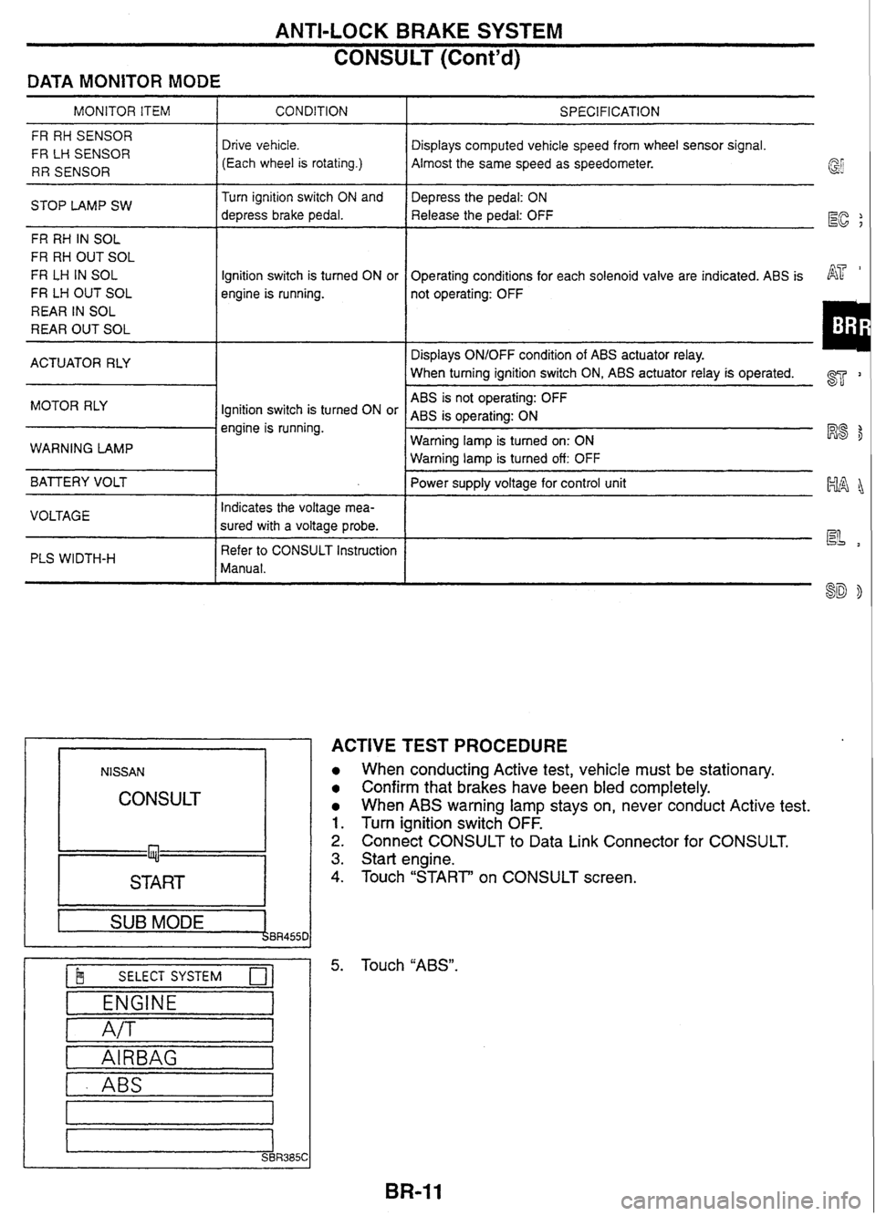
MONITOR ITEM I CONDITION
FR RH SENSOR
FR
LH SENSOR
RR SENSOR Drive vehicle.
(Each wheel is rotating.)
STOP LAMP SW Turn
ignition switch ON and
depress brake pedal.
FR RH
IN SOL
FR RH OUT SOL
FR
LH IN SOL
FR LH OUT SOL
REAR IN SOL
REAR OUT SOL Ignition
switch is turned ON or
engine is running.
ACTUATOR RLY
MOTOR RLY
Ignition switch is turned ON or
engine is running.
WARNING LAMP
BATTERY VOLT
I
VOLTAGE Indicates
the voltage mea-
sured with a voltage probe.
PLS WIDTH-H
I
Refer to CONSULT Instruction
Manual.
NlSSAN
CONSULT
START I --
1 SUB MODE BR455C
$ SELECT SYSTEM 0-
ENGINE
A/T
I - ABS I
SPECIFICATION
Displays computed vehicle speed from wheel sensor signal.
Almost the same speed as speedometer.
Depress the pedal: ON
Release the pedal: OFF
EC ;
Operating conditions for each solenoid valve are indicated. ABS is AT '
not operating: OFF
Displays ON/OFF condition of ABS actuator relay.
When turning ignition switch ON,
ABS actuator relay
is operated. 2
ABS is not operating: OFF
ABS
is operating: ON
Warning lamp is turned on: ON
R8 $
Warning lamp is turned off: OFF
Power supply voltage for control unit
~~~~
ACTIVE TEST PROCEDURE
When conducting Active test, vehicle must be stationary.
Confirm that brakes have been bled completely.
When ABS warning lamp stays on, never conduct Active test.
Turn ignition switch OFF.
Connect CONSULT to Data Link Connector for CONSULT.
Start engine.
Touch "START' on CONSULT screen.
Touch
"ABS".
Page 91 of 230
ANTI-LOCK BRAKE SYSTEM
CONSULT (Cont'd)
I b~ SELECT DiAG MODE 01 r SELF-DIAG RESULTS
DATA MONITOR
ACTIVE TEST
ECU
PART NUMBER I
FR RH SOL TEST
I 1 !!! SELECT MONITOR ITEM I I
I I SELECTION FROM MENU I I
I I START 1
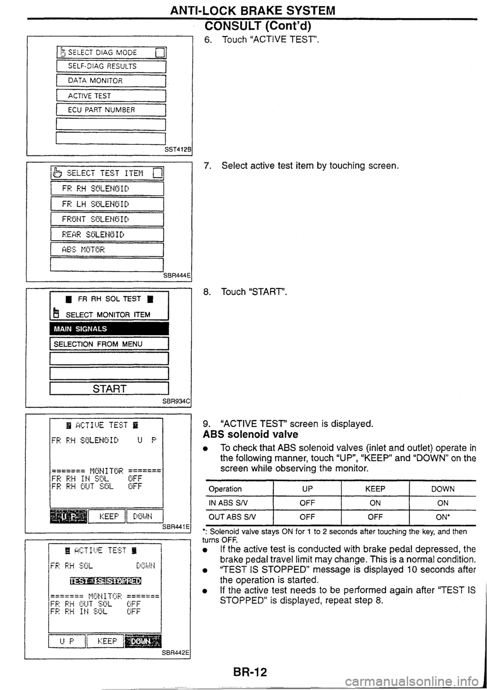
6. Touch "ACTIVE TEST'.
7. Select active test item by touching screen.
8. Touch "START'.
9. "ACTIVE TEST" screen is displayed.
ABS solenoid valve
To check that ABS solenoid valves (inlet and outlet) operate in
the following manner, touch
"UP*, "KEEP" and "DOWN" on the
screen while observing the monitor.
Operation I UP I KEEP ( DOWN
IN ABS SN I OFF 1 ON I ON
OUTABS SN I OFF I OFF I ON*
*: Solenoid valve stays ON for 1 to 2 seconds after touching the key, and then
turns OFF.
If the active test is conducted with brake pedal depressed, the
brake pedal travel limit may change. This is a normal condition.
"TEST IS STOPPED" message is displayed 10 seconds after
the operation is started.
If the active test needs to be performed again after "TEST IS
STOPPED" is displayed, repeat step 8.