sensor NISSAN LATIO 2009 Service Repair Manual
[x] Cancel search | Manufacturer: NISSAN, Model Year: 2009, Model line: LATIO, Model: NISSAN LATIO 2009Pages: 4331, PDF Size: 58.04 MB
Page 2957 of 4331
![NISSAN LATIO 2009 Service Repair Manual EM-10< PREPARATION >
[HR16DE]
PREPARATION
Tool name Description
Power tool Loosening bolts and nuts
Spark plug wrench Removing and installing spark plug
Valve seat cutter set Finishing valve seat dime NISSAN LATIO 2009 Service Repair Manual EM-10< PREPARATION >
[HR16DE]
PREPARATION
Tool name Description
Power tool Loosening bolts and nuts
Spark plug wrench Removing and installing spark plug
Valve seat cutter set Finishing valve seat dime](/img/5/57359/w960_57359-2956.png)
EM-10< PREPARATION >
[HR16DE]
PREPARATION
Tool name Description
Power tool Loosening bolts and nuts
Spark plug wrench Removing and installing spark plug
Valve seat cutter set Finishing valve seat dimensions
Piston ring expander Removing and installing piston ring
Valve guide drift Removing and installing valve guide
Valve guide reamer (1): Reaming valve guide inner hole (2): Reaming hole for oversize valve guide
(J-43897-18)
(J-43897-12)
Oxygen sensor thread cleaner Reconditioning the exhaust system threads
before installing a new heated oxygen sensor
(Use with anti-seize lubricant shown below.)
a = 18 mm (0.71 in) dia. for zirconia heated
oxygen sensor
b = 12 mm (0.47 in) dia. for titania heated
oxygen sensor PBIC0190E
PBIC3874E
S-NT048
S-NT030
PBIC4012E
PBIC4013E
AEM488
Page 2958 of 4331
EM
NP
O
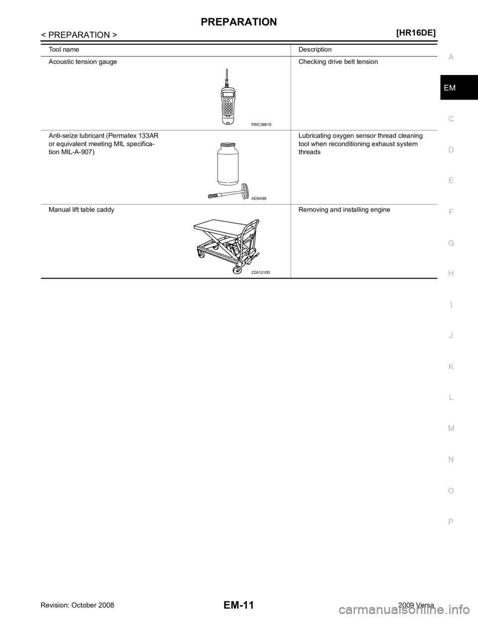
Acoustic tension gauge Checking drive belt tension
Anti-seize lubricant (Permatex 133AR
or equivalent meeting MIL specifica-
tion MIL-A-907) Lubricating oxygen sensor thread cleaning
tool when reconditioning exhaust system
threads
Manual lift table caddy Removing and installing engine
Tool name
Description AEM489
ZZA1210D
Page 2973 of 4331
Removal and Installation " .
2. Remove the air duct (inlet).
3. Remove the air cleaner filter from the air cleaner case. Refer to EM-17, " Removal and Installation " .
4. Remove the air duct [between air duct (inlet) and air cleaner case] from the air cleaner case.
5. Remove the PCV hose.
6. Remove the air duct (between air cleaner case and electric throttle control actuator). • Add marks as necessary for easier installation.
7. Disconnect harness connector from mass air flow sensor.
8. Remove air cleaner case.
9. Remove the mass air flow sensor from the air cleaner case, if necessary. CAUTION:
• Handle mass air flow sensor carefully and avoid impacts.
• Never touch sensor part.
INSTALLATION
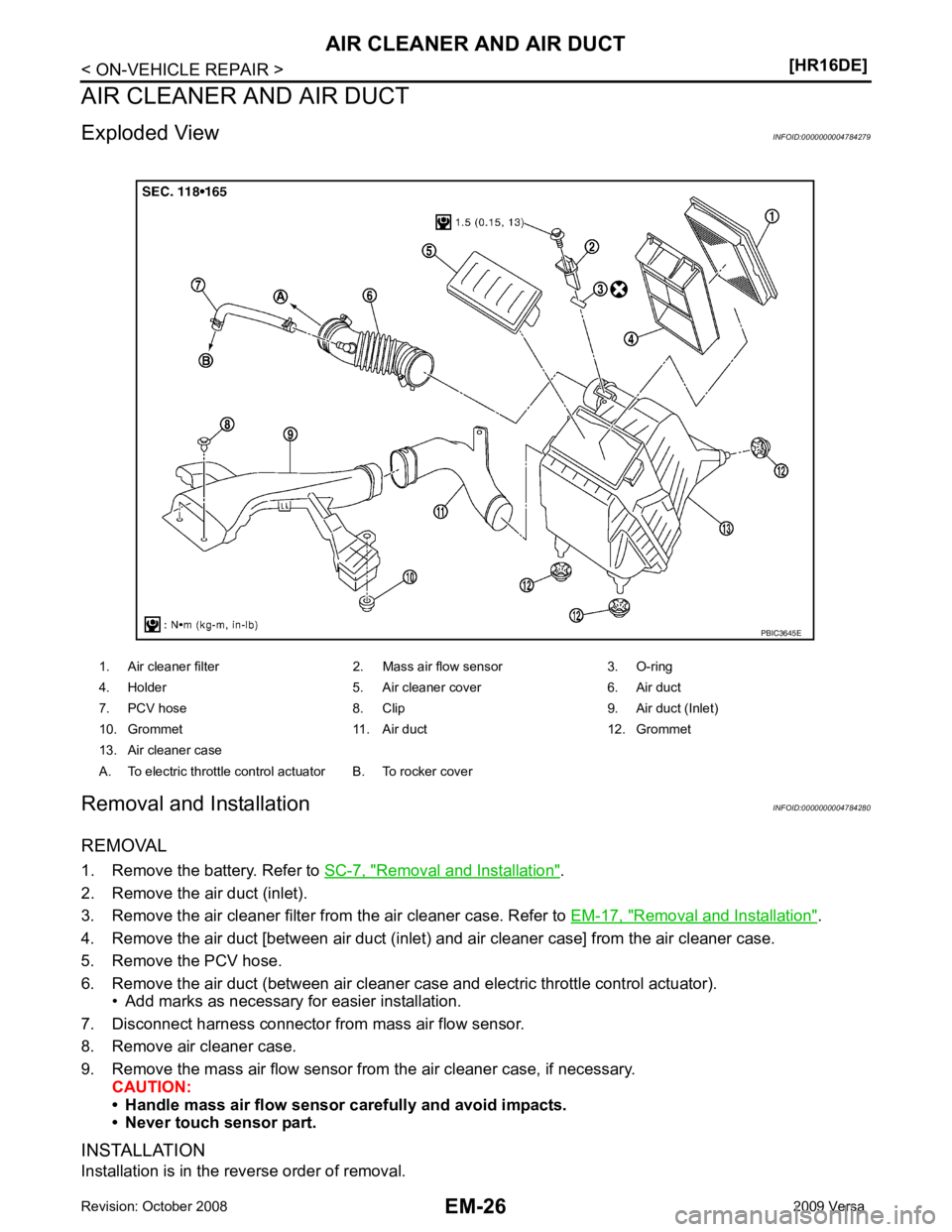
Installation is in the reverse order of removal. 1. Air cleaner filter 2. Mass air flow sensor 3. O-ring
4. Holder 5. Air cleaner cover 6. Air duct
7. PCV hose 8. Clip 9. Air duct (Inlet)
10. Grommet 11. Air duct 12. Grommet
13. Air cleaner case
A. To electric throttle control actuator B. To rocker cover
Page 2978 of 4331
EM
NP
O
EXHAUST MANIFOLD
Exploded View INFOID:0000000004784284
Removal and Installation INFOID:0000000004784285
REMOVAL 1. Remove the cowl. Refer to EI-22, " Removal and Installation " .
2. Remove exhaust front tube. Refer to EX-5, " Component " .
3. Remove the harness bracket of air fuel ratio sensor 1 from the cylinder head.
4. Remove exhaust manifold cover.
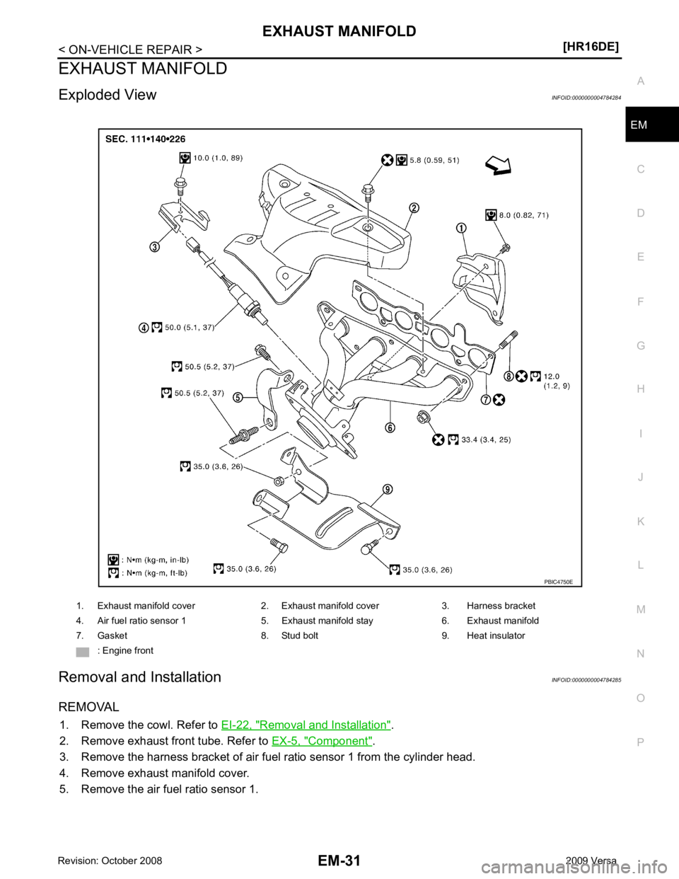
5. Remove the air fuel ratio sensor 1. 1. Exhaust manifold cover 2. Exhaust manifold cover 3. Harness bracket
4. Air fuel ratio sensor 1 5. Exhaust manifold stay 6. Exhaust manifold
7. Gasket 8. Stud bolt 9. Heat insulator : Engine front
Page 2980 of 4331
![NISSAN LATIO 2009 Service Repair Manual EXHAUST MANIFOLD
EM-33
< ON-VEHICLE REPAIR >
[HR16DE] C
D E
F
G H
I
J
K L
M A EM
NP
O
1. Tighten exhaust manifold nuts to specification in two stages in
the numerical order shown.
2. Use Tool NISSAN LATIO 2009 Service Repair Manual EXHAUST MANIFOLD
EM-33
< ON-VEHICLE REPAIR >
[HR16DE] C
D E
F
G H
I
J
K L
M A EM
NP
O
1. Tighten exhaust manifold nuts to specification in two stages in
the numerical order shown.
2. Use Tool](/img/5/57359/w960_57359-2979.png)
EXHAUST MANIFOLD
EM-33
< ON-VEHICLE REPAIR >
[HR16DE] C
D E
F
G H
I
J
K L
M A EM
NP
O
1. Tighten exhaust manifold nuts to specification in two stages in
the numerical order shown.
2. Use Tool (A) to install the air fuel ratio sensor 1. CAUTION:
• Handle it carefully and avoid impacts.
• Before installing a new air fu el ratio sensor 1, clean the
exhaust tube threads using suitable tool and approved
anti-seize lubricant.
• Do not over-tighten the air fu el ratio sensor 1. Doing so
may damage the air fuel rati o sensor 1, resulting in the
MIL coming on. : Engine front ALBIA0625ZZ
Tool number : KV10117100 ( — )
Tool number : — (J-43897-12)
Tool number : — (J-43897-18) PBIC3654E
Page 3005 of 4331
Rotation " .
2. Remove front fender protector (RH). Refer to EI-24, " Removal and Installation " .
3. Drain engine oil. Refer to LU-8, " Draining " .
CAUTION:
Be sure to perform this step when engine is cold.
4. Remove the following parts. • Intake manifold: Refer to EM-28, " Exploded View " .
• Drive belt: Refer to EM-15, " Removal and Installation " .
• Water pump pulley: Refer to CO-20, " Exploded View " .
• Ground cable (RH)
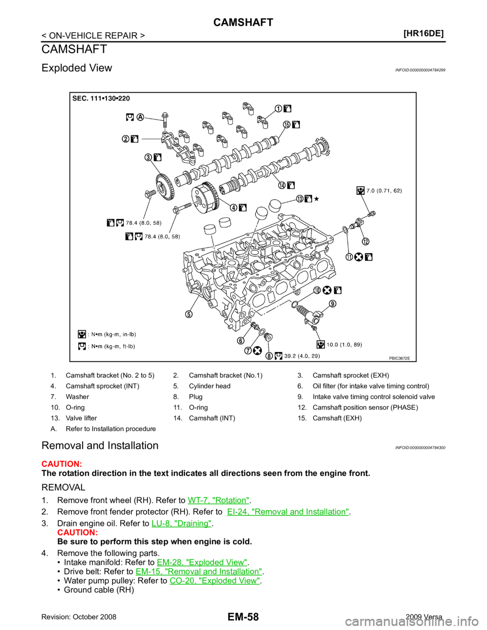
1. Camshaft bracket (No. 2 to 5) 2. Camshaft bracket (No.1) 3. Camshaft sprocket (EXH)
4. Camshaft sprocket (INT) 5. Cylinder head 6. Oil filter (for intake valve timing control)
7. Washer 8. Plug 9. Intake valve timing control solenoid valve
10. O-ring 11. O-ring 12. Camshaf t position sensor (PHASE)
13. Valve lifter 14. Camshaft (INT) 15. Camshaft (EXH)
A. Refer to Installation procedure
Page 3007 of 4331
![NISSAN LATIO 2009 Service Repair Manual EM-60< ON-VEHICLE REPAIR >
[HR16DE]
CAMSHAFT
a. Loosen bolts in the reverse of the order shown.
b. Cut liquid gasket by prying the position ( ) shown, and then remove the front cover.
10. Re NISSAN LATIO 2009 Service Repair Manual EM-60< ON-VEHICLE REPAIR >
[HR16DE]
CAMSHAFT
a. Loosen bolts in the reverse of the order shown.
b. Cut liquid gasket by prying the position ( ) shown, and then remove the front cover.
10. Re](/img/5/57359/w960_57359-3006.png)
EM-60< ON-VEHICLE REPAIR >
[HR16DE]
CAMSHAFT
a. Loosen bolts in the reverse of the order shown.
b. Cut liquid gasket by prying the position ( ) shown, and then remove the front cover.
10. Remove camshaft position sensor (PHASE) from rear end of cylinder head. CAUTION:
Handle it carefully and avoid impacts.
11. Remove camshaft sprocket (EXH) (1). CAUTION:
• Hold the camshaft hexagonal part (A), and then secure the
camshaft.
• Never rotate crankshaft and camshaft separately, so as not to contact valve with pist on in the following steps.
12. Turn the camshaft sprocket (INT) to the most advanced position. CAUTION:
Installation and removal of the camshaft sprocket (INT) must be done in the most advanced posi-
tion for the following reasons. KBIA3429J
PBIC3712E
AWBIA0102ZZ
Page 3017 of 4331
![NISSAN LATIO 2009 Service Repair Manual EM-70< ON-VEHICLE REPAIR >
[HR16DE]
CAMSHAFT
c. Tighten bolts in the numerical order shown.
d. After all bolts are tightened, retighten them to specified torque in numerical order as shown.
CAUTION:
B NISSAN LATIO 2009 Service Repair Manual EM-70< ON-VEHICLE REPAIR >
[HR16DE]
CAMSHAFT
c. Tighten bolts in the numerical order shown.
d. After all bolts are tightened, retighten them to specified torque in numerical order as shown.
CAUTION:
B](/img/5/57359/w960_57359-3016.png)
EM-70< ON-VEHICLE REPAIR >
[HR16DE]
CAMSHAFT
c. Tighten bolts in the numerical order shown.
d. After all bolts are tightened, retighten them to specified torque in numerical order as shown.
CAUTION:
Be sure to wipe off any excessive liquid gasket leaking to
surface.
22. Insert crankshaft pulley by aligning with crankshaft key. • When inserting crankshaft pulley with a plastic hamme r, tap on its center portion (not circumference).
CAUTION:
Never damage front oil seal lip section.
23. Tighten crankshaft pulley bolt with the following procedure: • Secure crankshaft pulley with a suitable tool, and tighten crankshaft pulley bolt.
a. Apply new engine oil to thread and seat surfaces of crankshaft pulley bolt.
b. Tighten crankshaft pulley bolt.
c. Put a paint mark (B) on crankshaft pulley, mating with any one of six easy to recognize angle marks (A) on crankshaft bolt flange
(1).
d. Turn another 60 degrees clockwise (angle tightening). • Check the tightening angle with movement of one angle mark.
24. Make sure that crankshaft turns smoothly by rotating by hand clockwise.
25. Install the camshaft position sensor (PHASE) to the rear end of cylinder head.
• Tighten bolts with it seated completely.
26. Check and adjust valve clearance. Refer to EM-20, " Inspection and Adjustment " .
27. Installation of the remaining components is in the reverse order of removal.
Inspection INFOID:0000000004784301
INSPECTION AFTER REMOVAL
Oil Filter KBIA3429J
Crankshaft pulley bolt : 35.0 N·m (3.6 kg-m, 26 ft-lb)
PBIC3726E
Page 3042 of 4331
EM
NP
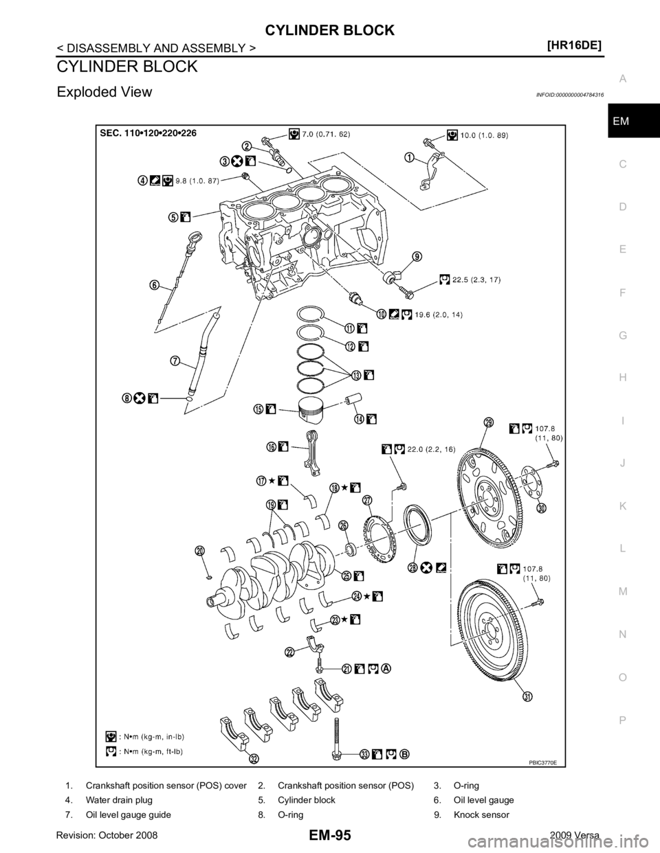
O
CYLINDER BLOCK
Exploded View INFOID:0000000004784316
1. Crankshaft position sensor (POS) cover 2. Crankshaft position sensor (POS) 3. O-ring
4. Water drain plug 5. Cylinder block 6. Oil level gauge
7. Oil level gauge guide 8. O-ring 9. Knock sensor
Page 3043 of 4331
Removal and Installation " .
2. Remove knock sensor. CAUTION:
Carefully handle knock sensor avoiding shocks.
3. Remove crankshaft position sensor (POS) and cover. CAUTION:
• Avoid impacts such as a dropping.
• Never disassemble.
• Keep it away from metal particles.
• Never place the sensor where it is exposed to magnetism.
4. Remove piston and connecting rod assembly with the following procedure: • Before removing piston and connecting rod assembly, check the connecting rod side clearance. Refer to
EM-103, " Inspection " .
a. Position crankshaft pin corresponding to connecting rod to be removed onto the bottom dead center.
b. Remove connecting rod cap.
c. Using a hammer handle or similar tool, push piston and connect- ing rod assembly out to the cylinder head side.
CAUTION:
• Be careful not to damage matching surface with connect-
ing rod cap.
• Be careful not to damage the cylinder wall and crankshaft pin, resulting from an inte rference of the connecting rod
big end.
5. Remove connecting rod bearings. CAUTION:
Identify installation positions, and store them without mixing up.
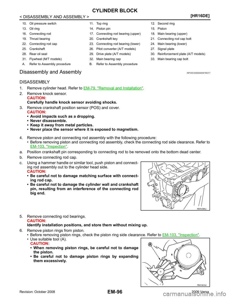
6. Remove piston rings from piston. • Before removing piston rings, check the piston ring side clearance. Refer to EM-103, " Inspection " .
• Use suitable tool (A).
CAUTION:
• When removing piston rings, be careful not to damage the piston.
• Be careful not to damage piston rings by expanding
them excessively.
10. Oil pressure switch 11. Top ring 12. Second ring
13. Oil ring 14. Piston pin 15. Piston
16. Connecting rod 17. Connecting rod bearing (upper) 18. Main bearing (upper)
19. Thrust bearing 20. Crankshaft key 21. Connecting rod cap bolt
22. Connecting rod cap 23. Connecting rod bearing (lower) 24. Main bearing (lower)
25. Crankshaft 26. Pilot converter (A/T models) 27. Signal plate
28. Rear oil seal 29. Drive plate (A/T models) 30. Reinforcement plate (A/T models)
31. Flywheel (M/T models) 32. Main bearing cap 33. Main bearing cap bolt
A. Refer to Assembly procedure B. Refer to Assembly procedure PBIC3233J