sensor NISSAN LATIO 2009 Service Repair Manual
[x] Cancel search | Manufacturer: NISSAN, Model Year: 2009, Model line: LATIO, Model: NISSAN LATIO 2009Pages: 4331, PDF Size: 58.04 MB
Page 3391 of 4331
IP
N
O P
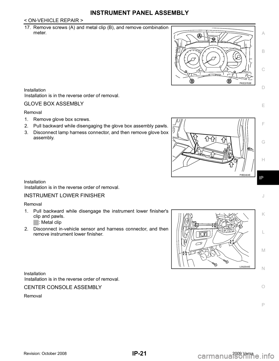
17. Remove screws (A) and metal clip (B), and remove combination
meter.
Installation Installation is in the reverse order of removal.
GLOVE BOX ASSEMBLY
Removal 1. Remove glove box screws.
2. Pull backward while disengaging the glove box assembly pawls.
3. Disconnect lamp harness connector, and then remove glove box assembly.
Installation Installation is in the reverse order of removal.
INSTRUMENT LOWER FINISHER
Removal 1. Pull backward while disengage the instrument lower finisher's clip and pawls.
: Metal clip
2. Disconnect in-vehicle sensor and harness connector, and then remove instrument lower finisher.
Installation Installation is in the reverse order of removal.
CENTER CONSOLE ASSEMBLY
Removal PIIB3404E
Page 3417 of 4331

Trouble Diagnosis Procedure " .
Abbreviation List INFOID:0000000004306697
Unit name abbreviations in CONSULT-III CAN diagnosis and in this section are as per the following list.
Abbreviation Unit name A-BAG Air bag diagnosis sensor unitABS ABS actuator and electric unit (control unit)
BCM BCM DLC Data link connector
ECM ECM EPS EPS control unit
I-KEY Intelligent Key unit
IPDM-E IPDM E/R M&A Combination meter
TCM TCM
Page 3418 of 4331
![NISSAN LATIO 2009 Service Repair Manual PRECAUTIONS
LAN-23
< PRECAUTION >
[CAN] C
D E
F
G H
I
J
L
M A
B LAN
N
O P
PRECAUTION
PRECAUTIONS
Precaution for Supplemental Restraint System (SRS) "AIR BAG" and "SEAT BELT
PRE-TENSIONER" INFOID:000 NISSAN LATIO 2009 Service Repair Manual PRECAUTIONS
LAN-23
< PRECAUTION >
[CAN] C
D E
F
G H
I
J
L
M A
B LAN
N
O P
PRECAUTION
PRECAUTIONS
Precaution for Supplemental Restraint System (SRS) "AIR BAG" and "SEAT BELT
PRE-TENSIONER" INFOID:000](/img/5/57359/w960_57359-3417.png)
PRECAUTIONS
LAN-23
< PRECAUTION >
[CAN] C
D E
F
G H
I
J
L
M A
B LAN
N
O P
PRECAUTION
PRECAUTIONS
Precaution for Supplemental Restraint System (SRS) "AIR BAG" and "SEAT BELT
PRE-TENSIONER" INFOID:0000000004498345
The Supplemental Restraint System such as “A IR BAG” and “SEAT BELT PRE-TENSIONER”, used along
with a front seat belt, helps to reduce the risk or severi ty of injury to the driver and front passenger for certain
types of collision. This system includes seat belt switch inputs and dual stage front air bag modules. The SRS
system uses the seat belt switches to determine the front air bag deployment, and may only deploy one front
air bag, depending on the severity of a collision and w hether the front occupants are belted or unbelted.
Information necessary to service the system safely is included in the “SRS AIRBAG” and “SEAT BELT” of this
Service Manual.
WARNING:
• To avoid rendering the SRS inoper ative, which could increase the risk of personal injury or death in
the event of a collision which would result in air bag inflation, all maintenance must be performed by
an authorized NISSAN/INFINITI dealer.
• Improper maintenance, including in correct removal and installation of the SRS, can lead to personal
injury caused by unintentional act ivation of the system. For removal of Spiral Cable and Air Bag
Module, see the “SRS AIRBAG”.
• Never use electrical test equipment on any circuit re lated to the SRS unless instructed to in this Ser-
vice Manual. SRS wiring harnesses can be identifi ed by yellow and/or orange harnesses or harness
connectors.
PRECAUTIONS WHEN USING POWER TOOLS (AIR OR ELECTRIC) AND HAMMERS WARNING:
• When working near the Airbag Diagnosis Sensor Un it or other Airbag System sensors with the igni-
tion ON or engine running, DO NOT use air or el ectric power tools or strike near the sensor(s) with a
hammer. Heavy vibration could activate the sensor( s) and deploy the air bag(s), possibly causing
serious injury.
• When using air or electric power tools or hammers , always switch the ignition OFF, disconnect the
battery, and wait at least 3 minutes before performing any service.
Precautions for Trouble Diagnosis INFOID:0000000004306699
CAUTION:
• Never apply 7.0 V or more to the measurement terminal.
• Use a tester with open terminal voltage of 7.0 V or less.
• Turn the ignition switch OFF and disconnect th e battery cable from the negative terminal when
checking the harness.
Precautions for Harness Repair INFOID:0000000004306700
• Solder the repaired area and wrap tape around the soldered area. NOTE:
A fray of twisted lines must be within 110 mm (4.33 in). SKIB8766E
Page 3422 of 4331

LAN
N
O P
Engine status signal T R
Fuel consumption monitor signal T R
Malfunction indicator lamp signal T R
Wide open throttle position signal T R R
A/C switch signal R T
Blower fan motor switch signal R T
Buzzer output signal T R
T R
Day time running light request signal *3
T R
Door lock/unlock status signal T R
Door switch signal T R R R
Front wiper request signal T R
High beam request signal T R R
Horn chirp signal T R
Ignition switch signal T R
Low beam request signal T R
Position lights request signal T R R
Rear window defogger switch signal T R
Sleep/wake up signal R T
T R R R
Theft warning horn request signal T R
Tire pressure signal *4
T R
Trunk open/close status signal T R
Turn indicator signal T R
EPS operation signal R T
EPS warning lamp signal T R
Door lock/unlock/trunk open request signal R T
Hazard request signal R T
Ignition knob switch signal R T
KEY warning lamp signal T R
LOCK warning lamp signal T R
Panic alarm request signal R T
Fuel level sensor signal R T
Overdrive control switch signal T R R
P/N range signal T R
Stop lamp switch signal T R R
Vehicle speed signal R R R R T
R R R T R
R*5
T*5
ABS warning lamp signal R T
Brake warning lamp signal R T
A/T check indicator signal R T Signal name/Connecting unitECM
BCM EPS
I-KEY
M&AABS
TCM *1
TCM *2
IPDM-E
Page 3424 of 4331
LAN
N
O P
COMPONENT DIAGNOSIS
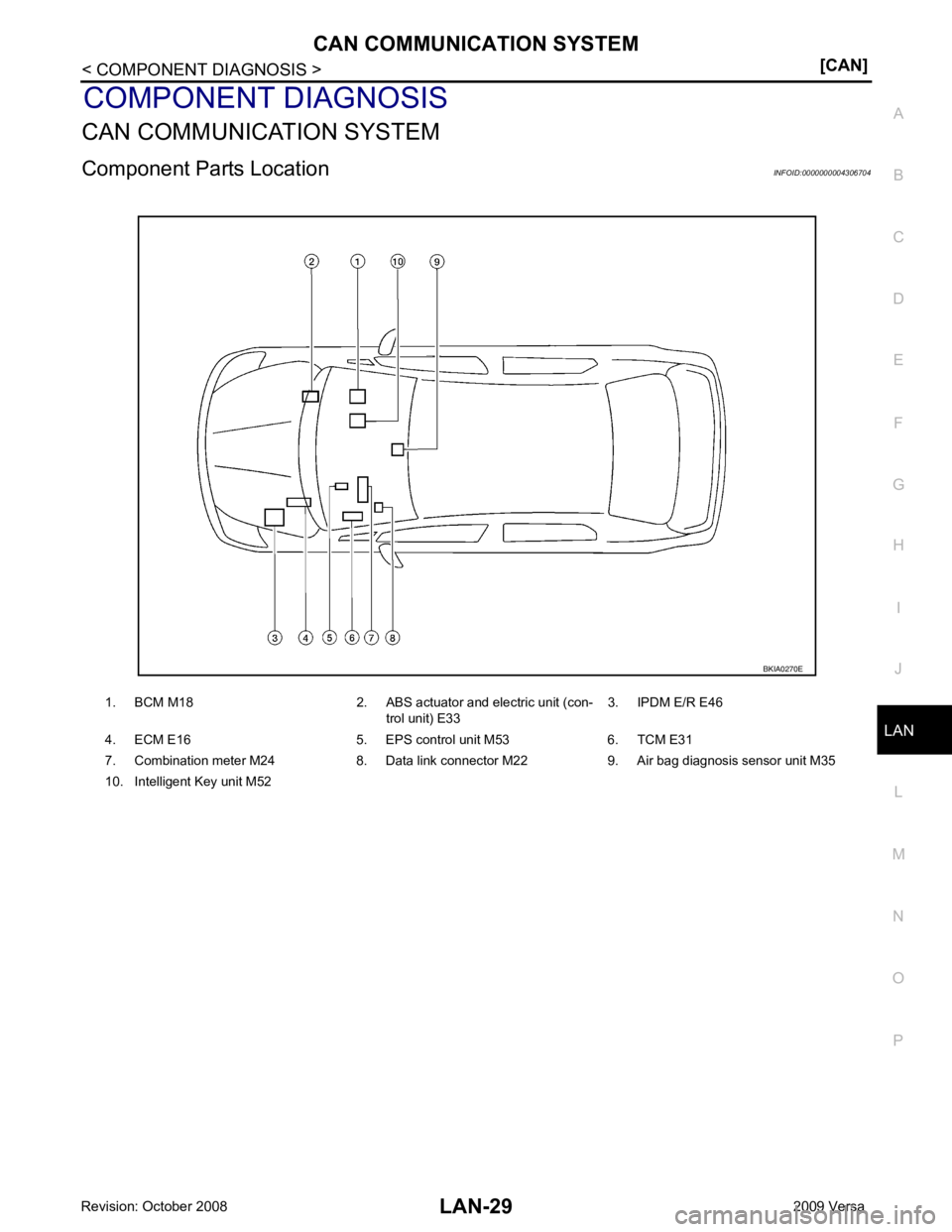
CAN COMMUNICATION SYSTEM
Component Parts Location INFOID:0000000004306704
1. BCM M18 2. ABS actuator and electric unit (con- trol unit) E333. IPDM E/R E46
4. ECM E16 5. EPS control unit M53 6. TCM E31
7. Combination meter M24 8. Data link connector M22 9. Air bag diagnosis sensor unit M35
10. Intelligent Key unit M52
Page 3707 of 4331
LT
N
O P
3. Perform the preliminary check. Refer to
LT-101, " Preliminary Check " .
4. Check symptom and repair or replace the cause of the malfunction.
5. Does the interior room lamp operate norma lly? If YES, GO TO 6. If NO, GO TO 4.
6. Inspection End
Preliminary Check INFOID:0000000004306634
CHECK POWER SUPPLY AND GROUND CIRCUIT FOR BCM Refer to BCS-15, " BCM Power Supply and Ground Circuit Inspection " .
CHECK POWER SUPPLY AND GROUND CIRCUIT FOR IPDM E/R Refer to LT-11, " Preliminary Check " .
CONSULT-III Function (BCM) INFOID:0000000004306635
Refer to LT-11, " CONSULT-III Function (BCM) " .
WORK SUPPORT
Display Item List
Reference between “MODE” and “TIME” for “TURN ON/OFF”
DATA MONITOR
Display Item List Item Description CONSULT-III
SET I/L D −UNLCK INTCON The 30 second operating function of the interior room lamps can be selected
when the front door LH is released (unlocked). ON/OFF
ROOM LAMP ON TIME SET The time in order to escalate illumination can be adjusted when interior room
lamps are turned on. MODE 1 – 7
ROOM LAMP OFF TIME SET The time in order to diminish illumination can be adjusted when interior room
lamps are turned off. MODE 1 – 7
MODE 1 2 3 4 5 6 7
Time (sec.) 0.5 1 2 3 4 5 0 Monitor item Contents
IGN ON SW “ON/OFF” Displays “IGN position (ON)/OFF, ACC position (OFF)” judged from ignition switch signal.
KEY ON SW “ON/OFF” Displays “Key inse rted (ON)/key removed (OFF)” status judged from key switch signal.
DOOR SW - DR “ON/OFF” Displays status of front door LH as judged from front door switch LH signal. (Door is open:
ON/Door is closed: OFF)
DOOR SW - AS “ON/OFF” Displays “Door open (ON)/Door closed (OFF)” status, determined from front door switch
RH signal.
DOOR SW - RR “ON/OFF” Displays “Door open (ON)/Door closed (OFF)” status, determined from rear door switch
RH signal.
DOOR SW - RL “ON/OFF” Displays “Door open (ON)/Door closed (OFF) ” status, determined from rear door switch
LH signal.
TRUNK “ON/OFF” Displays "Back door/Trunk open (ON)/closed (OFF)" status, determined from the back
door switch (hatchback) or the trunk lamp switch (sedan).
LOCK STATUS “ON/OFF” Display status (door is locked: ON/door is unlocked: OFF) of front door lock actuator LH
(unlock sensor) judged from the front door lock actuator LH (unlock sensor) signal.
CDL LOCK SW “ON/OFF” Displays “Door locked (ON)/Door unlocked (OFF) status, determined from locking detec-
tion switch in the front door LH.
CDL UNLOCK SW “ON/OFF” Displays “Door unlocked (OFF)” status, determined from locking detection switch in front
door RH.
Page 3732 of 4331
LU
NP
O
SERVICE INFORMATION
PRECAUTIONS
Precaution for Supplemental Restraint System (SRS) "AIR BAG" and "SEAT BELT
PRE-TENSIONER" INFOID:0000000004784384
The Supplemental Restraint System such as “A IR BAG” and “SEAT BELT PRE-TENSIONER”, used along
with a front seat belt, helps to reduce the risk or severi ty of injury to the driver and front passenger for certain
types of collision. This system includes seat belt switch inputs and dual stage front air bag modules. The SRS
system uses the seat belt switches to determine the front air bag deployment, and may only deploy one front
air bag, depending on the severity of a collision and w hether the front occupants are belted or unbelted.
Information necessary to service the system safely is included in the SRS and SB section of this Service Man-
ual.
WARNING:
• To avoid rendering the SRS inoper ative, which could increase the risk of personal injury or death in
the event of a collision which would result in air bag inflation, all maintenance must be performed by
an authorized NISSAN/INFINITI dealer.
• Improper maintenance, including in correct removal and installation of the SRS can lead to personal
injury caused by unintentional act ivation of the system. For removal of Spiral Cable and Air Bag
Module, see the SRS section.
• Do not use electrical test equipm ent on any circuit related to the SRS unless instructed to in this
Service Manual. SRS wiring harnesses can be identi fied by yellow and/or orange harnesses or har-
ness connectors.
• When working near the Airbag Diagnosis Sensor Un it or other Airbag System sensors with the Igni-
tion ON or engine running, DO NOT use air or el ectric power tools or strike near the sensor(s) with a
hammer. Heavy vibration could activate the sensor( s) and deploy the air bag(s), possibly causing
serious injury.
• When using air or electric power tools or hammers , always switch the Ignition OFF, disconnect the
battery, and wait at least 3 minutes before performing any service.
Precaution Necessary for Steering Wh eel Rotation After Battery Disconnect
INFOID:0000000004673030
NOTE:
• This Procedure is applied only to models with Inte lligent Key system and NATS (NISSAN ANTI-THEFT SYS-
TEM).
• Remove and install all control units after disconnecti ng both battery cables with the ignition knob in the
″ LOCK ″ position.
• Always use CONSULT-III to perform self-diagnosis as a part of each function inspection after finishing work.
If DTC is detected, perform trouble diagnosis according to self-diagnostic results.
For models equipped with the Intelligent Key system and NATS , an electrically controlled steering lock mech-
anism is adopted on the key cylinder.
For this reason, if the battery is disconnected or if the battery is discharged, the steering wheel will lock and
steering wheel rotation will become impossible.
If steering wheel rotation is required when battery pow er is interrupted, follow the procedure below before
starting the repair operation.
OPERATION PROCEDURE 1. Connect both battery cables. NOTE:
Supply power using jumper cables if battery is discharged.
2. Use the Intelligent Key or mechanical key to turn the ignition switch to the ″ACC ″ position. At this time, the
steering lock will be released.
3. Disconnect both battery cables. The steering lock will remain released and the steering wheel can be
rotated.
4. Perform the necessary repair operation.
5. When the repair work is completed, return the ignition switch to the ″LOCK ″ position before connecting
the battery cables. (At this time, the steering lock mechanism will engage.)
6. Perform a self-diagnosis check of al l control units using CONSULT-III.
Page 3746 of 4331
MA
N
O P
SERVICE INFORMATION
PRECAUTIONS
Precaution for Supplemental Restraint System (SRS) "AIR BAG" and "SEAT BELT
PRE-TENSIONER" INFOID:0000000004803408
The Supplemental Restraint System such as “A IR BAG” and “SEAT BELT PRE-TENSIONER”, used along
with a front seat belt, helps to reduce the risk or severi ty of injury to the driver and front passenger for certain
types of collision. This system includes seat belt switch inputs and dual stage front air bag modules. The SRS
system uses the seat belt switches to determine the front air bag deployment, and may only deploy one front
air bag, depending on the severity of a collision and w hether the front occupants are belted or unbelted.
Information necessary to service the system safely is included in the SRS and SB section of this Service Man-
ual.
WARNING:
• To avoid rendering the SRS inoper ative, which could increase the risk of personal injury or death in
the event of a collision which would result in air bag inflation, all maintenance must be performed by
an authorized NISSAN/INFINITI dealer.
• Improper maintenance, including in correct removal and installation of the SRS can lead to personal
injury caused by unintentional act ivation of the system. For removal of Spiral Cable and Air Bag
Module, see the SRS section.
• Do not use electrical test equipm ent on any circuit related to the SRS unless instructed to in this
Service Manual. SRS wiring harnesses can be identi fied by yellow and/or orange harnesses or har-
ness connectors.
PRECAUTIONS WHEN USING POWER TOOLS (AIR OR ELECTRIC) AND HAMMERS WARNING:
• When working near the Airbag Diagnosis Sensor Un it or other Airbag System sensors with the Igni-
tion ON or engine running, DO NOT use air or el ectric power tools or strike near the sensor(s) with a
hammer. Heavy vibration could activate the sensor( s) and deploy the air bag(s), possibly causing
serious injury.
• When using air or electric power tools or hammers , always switch the Ignition OFF, disconnect the
battery, and wait at least 3 minutes before performing any service.
Precaution Necessary for Steering Wh eel Rotation After Battery Disconnect
INFOID:0000000004803409
NOTE:
• This Procedure is applied only to models with Inte lligent Key system and NATS (NISSAN ANTI-THEFT SYS-
TEM).
• Remove and install all control units after disconnecti ng both battery cables with the ignition knob in the
″ LOCK ″ position.
• Always use CONSULT-III to perform self-diagnosis as a part of each function inspection after finishing work.
If DTC is detected, perform trouble diagnosis according to self-diagnostic results.
For models equipped with the Intelligent Key system and NATS , an electrically controlled steering lock mech-
anism is adopted on the key cylinder.
For this reason, if the battery is disconnected or if the battery is discharged, the steering wheel will lock and
steering wheel rotation will become impossible.
If steering wheel rotation is required when battery pow er is interrupted, follow the procedure below before
starting the repair operation.
OPERATION PROCEDURE 1. Connect both battery cables. NOTE:
Supply power using jumper cables if battery is discharged.
2. Use the Intelligent Key or mechanical key to turn the ignition switch to the ″ACC ″ position. At this time, the
steering lock will be released.
3. Disconnect both battery cables. The steering lock will remain released and the steering wheel can be
rotated.
4. Perform the necessary repair operation.
Page 3772 of 4331
ENGINE MAINTENANCE (MR18DE)
MA-29
< SERVICE INFORMATION >
C
D E
F
G H
I
J
K
M A
B MA
N
O P
CAUTION:
Be sure to clean radiator drain plug and install with new O-ring. Refer to CO-38, " Component " .
3. Fill radiator and reservoir tank with water and reinstall radiator cap.
4. Run engine and warm it up to normal operating temperature.
5. Rev engine two or three times under no-load.
6. Stop engine and wait until it cools down.
7. Drain water from the cooling system.
8. Repeat steps 1 through 7 until clear water begins to drain from radiator.
FUEL LINES
FUEL LINES : Checking Fuel Line INFOID:0000000004683691
Inspect fuel lines, fuel filler cap and fuel tank for improper attach-
ment, leaks, cracks, damage, loos e connections, chafing or deterio-
ration.
If necessary, repair or replace damaged parts.
AIR CLEANER FILTER
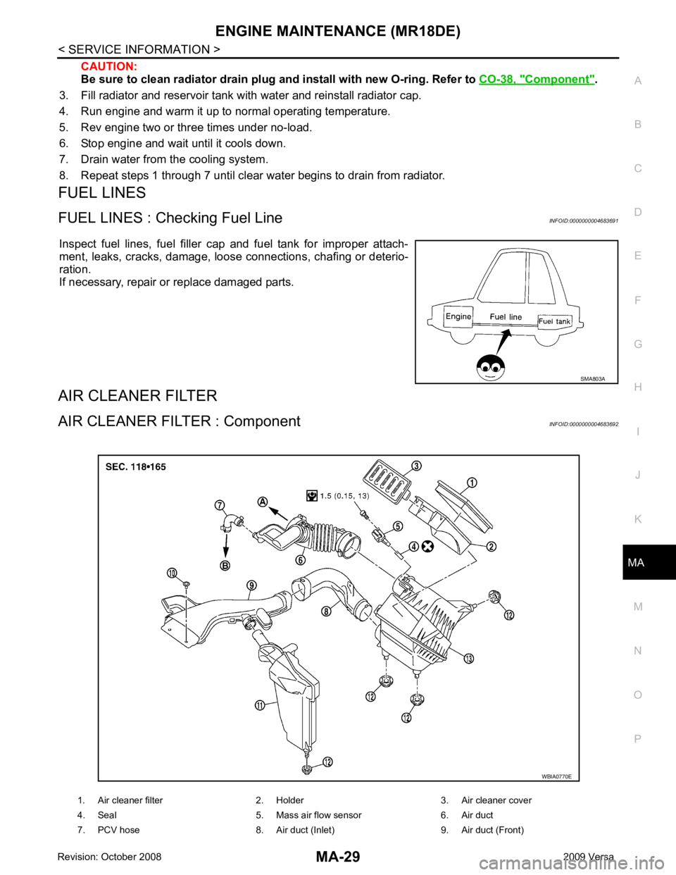
AIR CLEANER FILTER : Component INFOID:0000000004683692 SMA803A
1. Air cleaner filter 2. Holder 3. Air cleaner cover
4. Seal 5. Mass air flow sensor 6. Air duct
7. PCV hose 8. Air duct (Inlet) 9. Air duct (Front) WBIA0770E
Page 3797 of 4331
MT
N
O P
SERVICE INFORMATION
PRECAUTIONS
Precaution for Supplemental Restraint System (SRS) "AIR BAG" and "SEAT BELT
PRE-TENSIONER" INFOID:0000000004786253
The Supplemental Restraint System such as “A IR BAG” and “SEAT BELT PRE-TENSIONER”, used along
with a front seat belt, helps to reduce the risk or severi ty of injury to the driver and front passenger for certain
types of collision. This system includes seat belt switch inputs and dual stage front air bag modules. The SRS
system uses the seat belt switches to determine the front air bag deployment, and may only deploy one front
air bag, depending on the severity of a collision and w hether the front occupants are belted or unbelted.
Information necessary to service the system safely is included in the SRS and SB section of this Service Man-
ual.
WARNING:
• To avoid rendering the SRS inoper ative, which could increase the risk of personal injury or death in
the event of a collision which would result in air bag inflation, all maintenance must be performed by
an authorized NISSAN/INFINITI dealer.
• Improper maintenance, including in correct removal and installation of the SRS can lead to personal
injury caused by unintentional act ivation of the system. For removal of Spiral Cable and Air Bag
Module, see the SRS section.
• Do not use electrical test equipm ent on any circuit related to the SRS unless instructed to in this
Service Manual. SRS wiring harnesses can be identi fied by yellow and/or orange harnesses or har-
ness connectors.
• When working near the Airbag Diagnosis Sensor Un it or other Airbag System sensors with the Igni-
tion ON or engine running, DO NOT use air or el ectric power tools or strike near the sensor(s) with a
hammer. Heavy vibration could activate the sensor( s) and deploy the air bag(s), possibly causing
serious injury.
• When using air or electric power tools or hammers , always switch the Ignition OFF, disconnect the
battery, and wait at least 3 minutes before performing any service.