NISSAN NAVARA 2005 Repair Workshop Manual
NAVARA 2005
NISSAN
NISSAN
https://www.carmanualsonline.info/img/5/57362/w960_57362-0.png
NISSAN NAVARA 2005 Repair Workshop Manual
Trending: recommended oil, fuel fill door release, bulb, fuel filter location, tow bar, battery capacity, radio
Page 1731 of 3171
INSIDE MIRROR
GW-45
C
D
E
F
G
H
J
K
L
MA
B
GW
INSIDE MIRRORPFP:96321
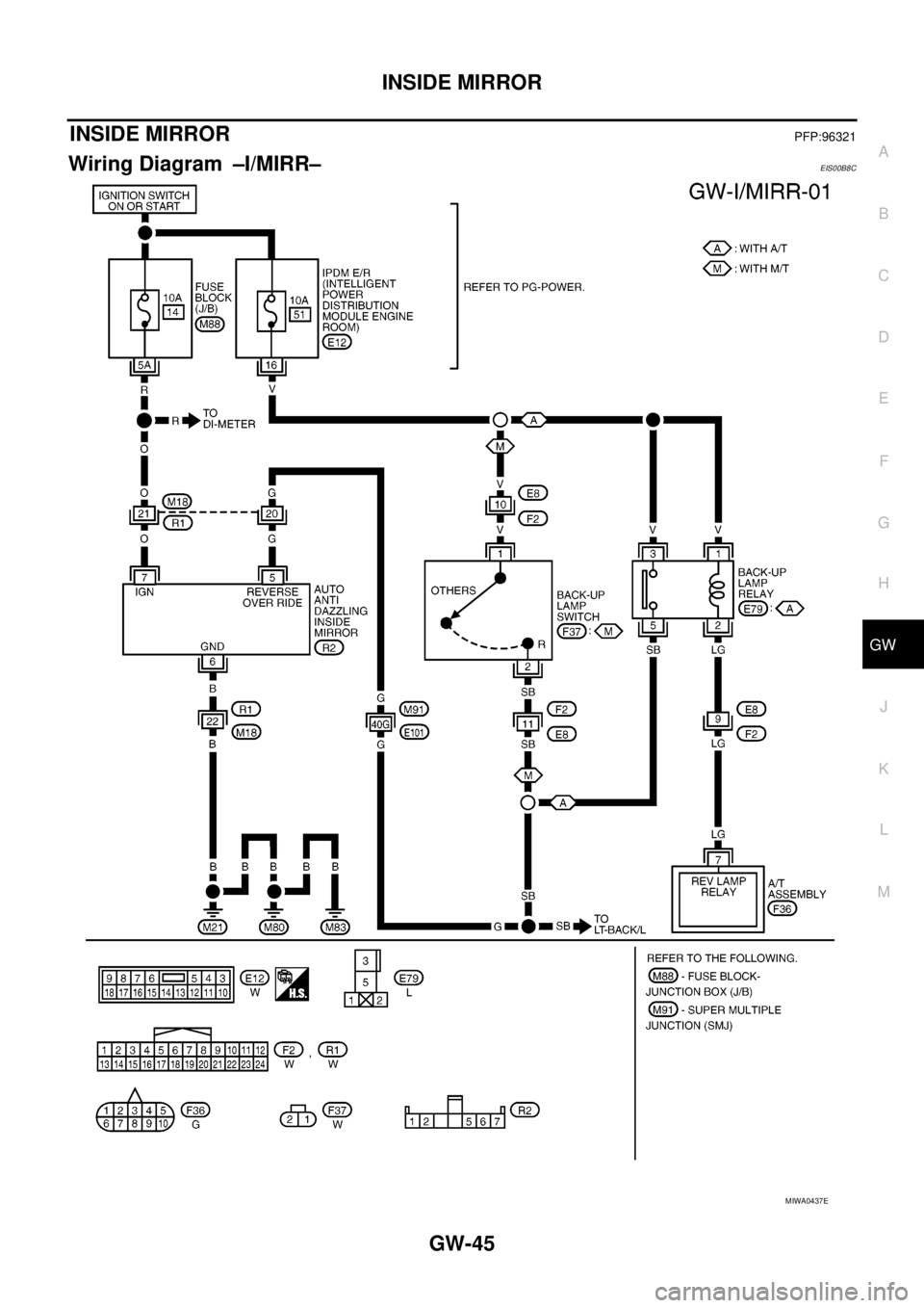
Wiring Diagram –I/MIRR–EIS00B8C
MIWA0437E
Page 1732 of 3171
GW-46
INSIDE MIRROR
Removal and Installation
EIS00B8D
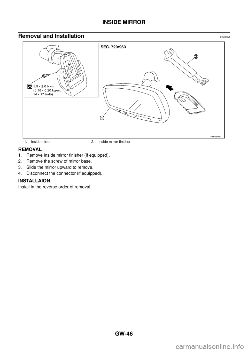
REMOVAL
1. Remove inside mirror finisher (if equipped).
2. Remove the screw of mirror base.
3. Slide the mirror upward to remove.
4. Disconnect the connector (if equipped).
INSTALLAION
Install in the reverse order of removal.
1. Inside mirror 2. Inside mirror finisher
MIIB0645E
Page 1733 of 3171
REAR WINDOW DEFOGGER
GW-47
C
D
E
F
G
H
J
K
L
MA
B
GW
REAR WINDOW DEFOGGERPFP:25350
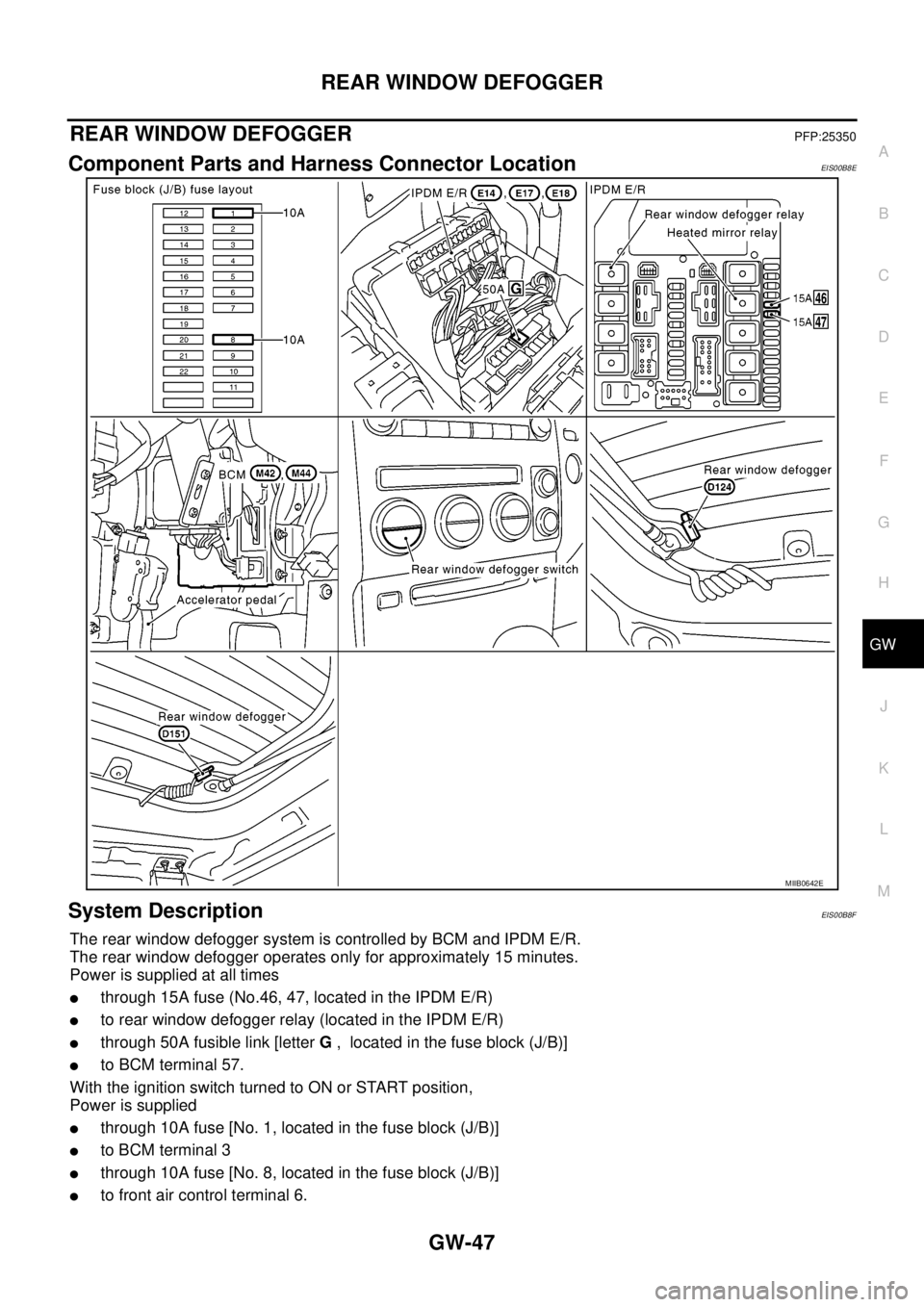
Component Parts and Harness Connector LocationEIS00B8E
System DescriptionEIS00B8F
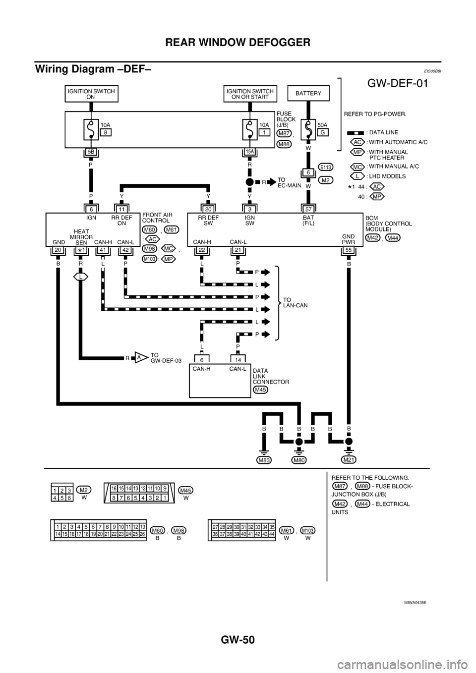
The rear window defogger system is controlled by BCM and IPDM E/R.
The rear window defogger operates only for approximately 15 minutes.
Power is supplied at all times
lthrough 15A fuse (No.46, 47, located in the IPDM E/R)
lto rear window defogger relay (located in the IPDM E/R)
lthrough 50A fusible link [letterG, located in the fuse block (J/B)]
lto BCM terminal 57.
WiththeignitionswitchturnedtoONorSTARTposition,
Power is supplied
lthrough 10A fuse [No. 1, located in the fuse block (J/B)]
lto BCM terminal 3
lthrough 10A fuse [No. 8, located in the fuse block (J/B)]
lto front air control terminal 6.
MIIB0642E
Page 1734 of 3171
GW-48
REAR WINDOW DEFOGGER
Ground is supplied
lto BCM terminal 55
lto front air control terminal 20
lthrough body grounds M21, M80 and M83
lto IPDM E/R terminals 38 and 59
lthrough body grounds E21, E41 and E61.
When front air control (rear window defogger switch) is turned to ON,
Ground is supplied
lto BCM terminal 20
lthrough front air control terminal 11
lthrough front air control terminal 20
lthrough body grounds M21, M80 and M83.
Then rear window defogger switch is illuminated.
Then BCM recognizes that rear window defogger switch is turned to ON.
Then it sends rear window defogger switch signals to IPDM E/R via DATA LINE (CAN H, CAN L).
When display panel receives rear window defogger switch signals it illuminates on the screen.
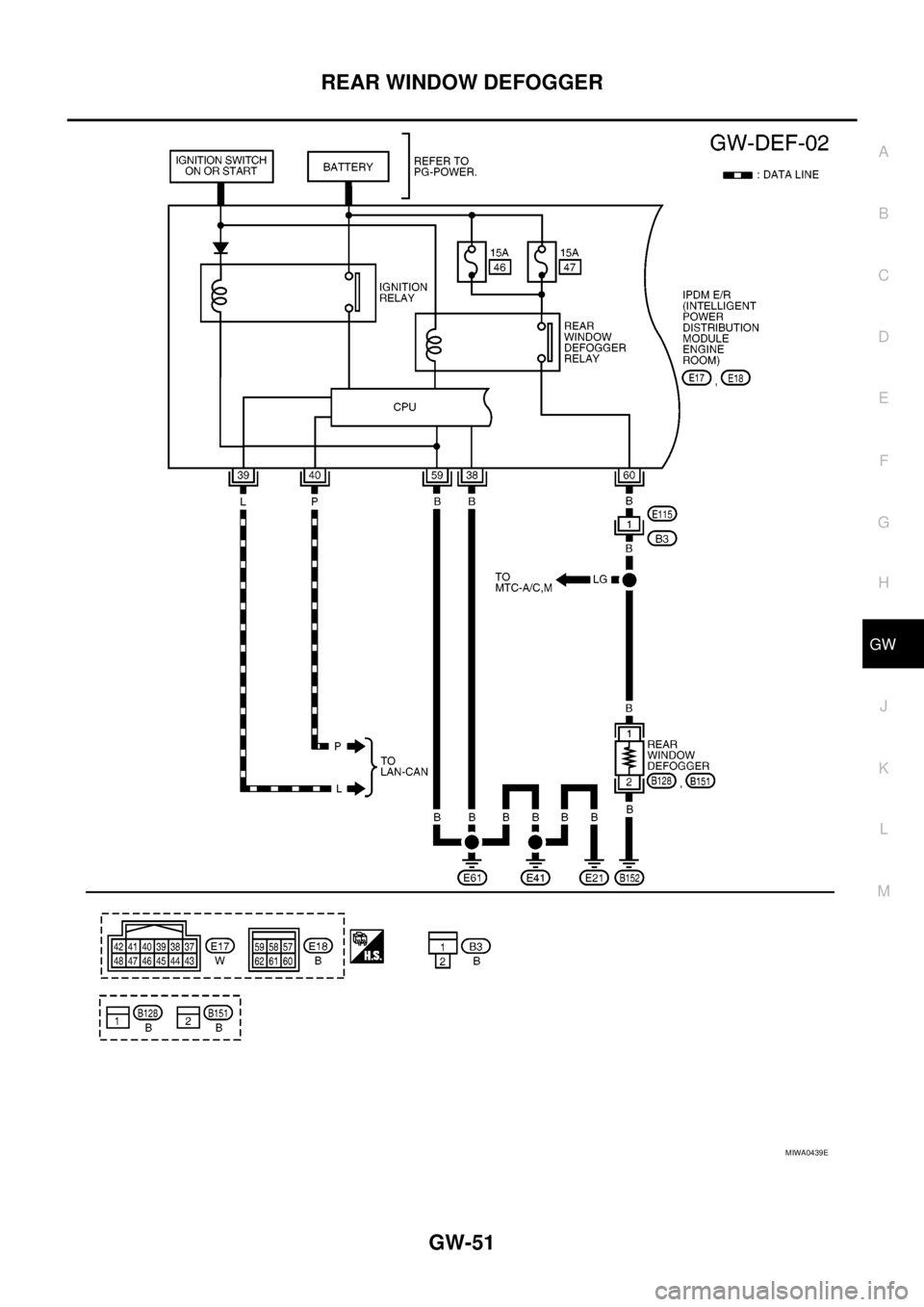
When IPDM E/R receives rear window defogger switch signals,
Ground is supplied
lto rear window defogger relay (located in the IPDM E/R)
lthrough IPDM E/R terminals 38 and 59
lthrough body grounds E21, E41 and E61
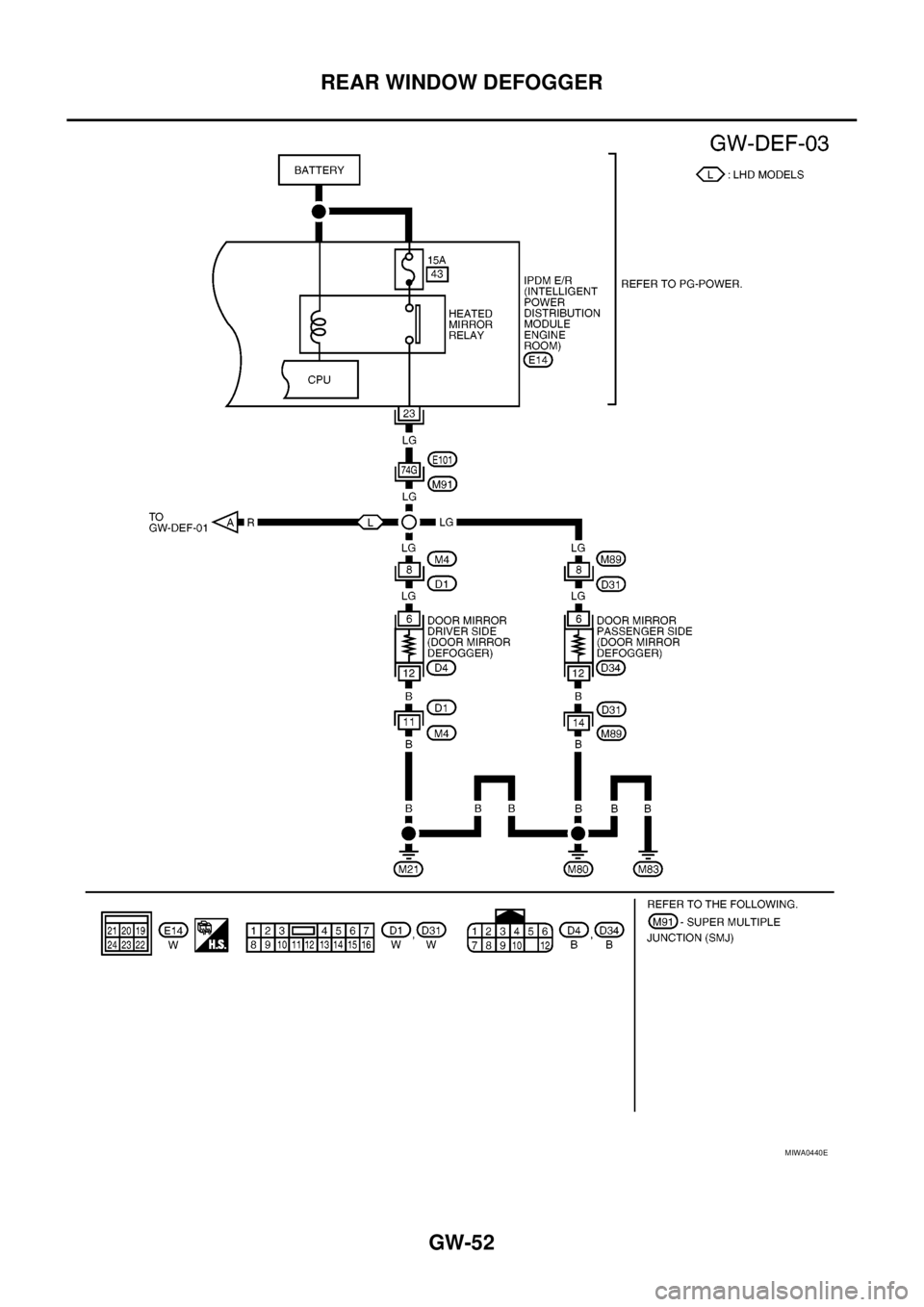
and then rear window defogger relay and heated mirror is energized.
Power is supplied
lthrough IPDM E/R terminal 60
lto rear window defogger terminal 1.
Ground is supplied
lto rear window window defogger terminal 2
lthrough body ground D152.
With power and ground supplied, rear window defogger filaments heat and defog the rear window.
CAN Communication System DescriptionEIS00B8G
Refer toLAN-23, "CAN COMMUNICATION".
Page 1735 of 3171
REAR WINDOW DEFOGGER
GW-49
C
D
E
F
G
H
J
K
L
MA
B
GW
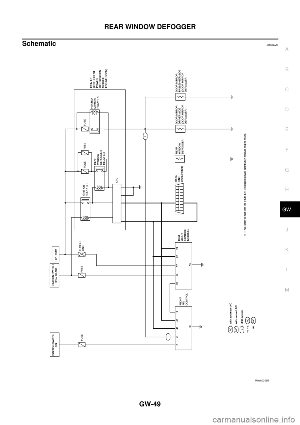
SchematicEIS00DZ9
MIWA0305E
Page 1736 of 3171
GW-50
REAR WINDOW DEFOGGER
Wiring Diagram –DEF–
EIS00B8I
MIWA0438E
Page 1737 of 3171
REAR WINDOW DEFOGGER
GW-51
C
D
E
F
G
H
J
K
L
MA
B
GW
MIWA0439E
Page 1738 of 3171
GW-52
REAR WINDOW DEFOGGER
MIWA0440E
Page 1739 of 3171
REAR WINDOW DEFOGGER
GW-53
C
D
E
F
G
H
J
K
L
MA
B
GW
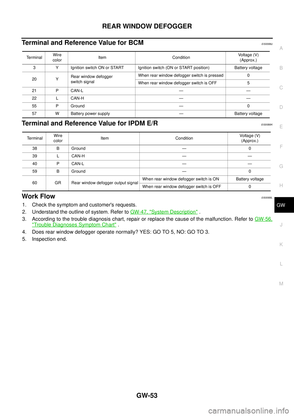
Terminal and Reference Value for BCMEIS00B8J
Terminal and Reference Value for IPDM E/REIS00B8K
Work FlowEIS00B8L
1. Check the symptom and customer's requests.
2. Understand the outline of system. Refer toGW-47, "
System Description".
3. According to the trouble diagnosis chart, repair or replace the cause of the malfunction. Refer toGW-56,
"Trouble Diagnoses Symptom Chart".
4. Does rear window defogger operate normally? YES: GO TO 5, NO: GO TO 3.
5. Inspection end.
TerminalWire
colorItem ConditionVoltage (V)
(Approx.)
3 Y Ignition switch ON or START Ignition switch (ON or START position) Battery voltage
20 YRear window defogger
switch signalWhen rear window defogger switch is pressed 0
When rear window defogger switch is OFF 5
21 P CAN-L — —
22 L CAN-H — —
55 P Ground — 0
57 W Battery power supply — Battery voltage
Te r m i n a lWire
colorItem ConditionVoltag e (V)
(Approx.)
38 B Ground — 0
39 L CAN-H — —
40 P CAN-L — —
59 B Ground — 0
60 GR Rear window defogger output signalWhen rear window defogger switch is ON Battery voltage
When rear window defogger switch is OFF 0
Page 1740 of 3171
GW-54
REAR WINDOW DEFOGGER
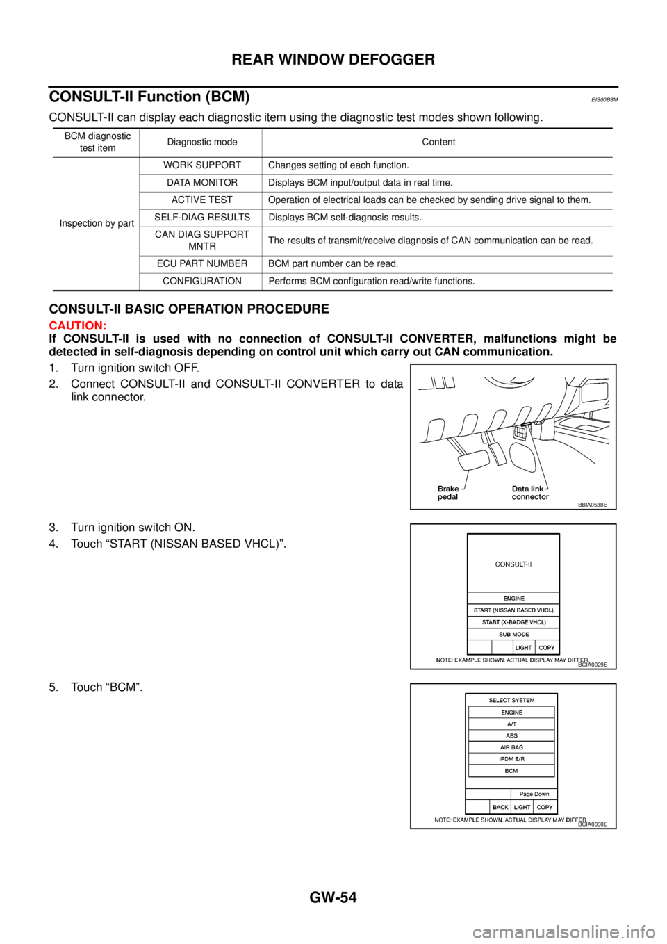
CONSULT-II Function (BCM)
EIS00B8M
CONSULT-II can display each diagnostic item using the diagnostic test modes shown following.
CONSULT-II BASIC OPERATION PROCEDURE
CAUTION:
If CONSULT-II is used with no connection of CONSULT-II CONVERTER, malfunctions might be
detected in self-diagnosis depending on control unit which carry out CAN communication.
1. Turn ignition switch OFF.
2. Connect CONSULT-II and CONSULT-II CONVERTER to data
link connector.
3. Turn ignition switch ON.
4. Touch “START (NISSAN BASED VHCL)”.
5. Touch “BCM”.
BCM diagnostic
test itemDiagnostic mode Content
Inspection by partWORK SUPPORT Changes setting of each function.
DATA MONITOR Displays BCM input/output data in real time.
ACTIVE TEST Operation of electrical loads can be checked by sending drive signal to them.
SELF-DIAG RESULTS Displays BCM self-diagnosis results.
CAN DIAG SUPPORT
MNTRThe results of transmit/receive diagnosis of CAN communication can be read.
ECU PART NUMBER BCM part number can be read.
CONFIGURATION Performs BCM configuration read/write functions.
BBIA0538E
BCIA0029E
BCIA0030E
Trending: adding oil, instrument cluster, Brc, transmission fluid, wheel, radiator, oil capacity
