NISSAN NAVARA 2005 Repair Workshop Manual
NAVARA 2005
NISSAN
NISSAN
https://www.carmanualsonline.info/img/5/57362/w960_57362-0.png
NISSAN NAVARA 2005 Repair Workshop Manual
Trending: glove box, radiator cap, adding oil, fuel injector, fuses, Engine lubrication system, Em-49
Page 2111 of 3171
LT-28
HEADLAMP -CONVENTIONAL TYPE-
Aiming Adjustment
EKS00P7Y
For details, refer to the regulations in your state.
Before performing aiming adjustment, check the following.
1. Ensure all tires are inflated to correct pressure.
2. Place vehicle and screen on level surface.
3. Ensure there is no load in vehicle other than the driver (or equivalent weight placed in driver's position).
Coolant and engine oil filled to correct level, and fuel tank full.
4. Confirm spare tire, jack and tools are properly stowed.
LOW BEAM AND HIGH BEAM
NOTE:
Aim each headlamp individually and ensure other headlamp beam pattern is blocked from screen.
1. Turn headlamp low beam ON.
2. Use adjusting screws to perform aiming adjustment.
lFirst tighten the adjusting screw all the way and then make adjustment by loosening the screw.
If the vehicle front body has been repaired and/or the headlamp assembly has been replaced, check
aiming. Use the aiming chart shown in the figure.
PKIC1216E
Page 2112 of 3171
HEADLAMP -CONVENTIONAL TYPE-
LT-29
C
D
E
F
G
H
I
J
L
MA
B
LT
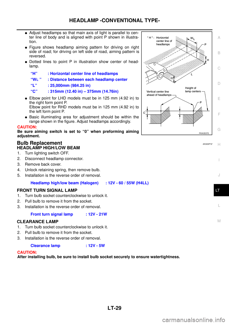
lAdjust headlamps so that main axis of light is parallel to cen-
ter line of body and is aligned with point P shown in illustra-
tion.
lFigure shows headlamp aiming pattern for driving on right
side of road; for driving on left side of road, aiming pattern is
reversed.
lDotted lines to point P in illustration show center of head-
lamp.
lElbow point for LHD models must be in 125 mm (4.92 in) to
the right form point P.
Elbow point for RHD models must be in 125 mm (4.92 in) to
the left form point P.
lBasic illuminating area for adjustment should be within the
range shown in the figure. Adjust headlamps accordingly.
CAUTION:
Be sure aiming switch is set to “0” when preforming aiming
adjustment.
Bulb ReplacementEKS00P7Z
HEADLAMP HIGH/LOW BEAM
1. Turn lighting switch OFF.
2. Disconnect headlamp connector.
3. Remove back cover.
4. Unlock retaining spring, then remove bulb.
5. Installation is the reverse order of removal.
FRONT TURN SIGNAL LAMP
1. Turn bulb socket counterclockwise to unlock it.
2. Pull bulb to remove it from the socket.
3. Installation is the reverse order of removal.
CLEARANCE LAMP
1. Turn bulb socket counterclockwise to unlock it.
2. Pull bulb to remove it from the socket.
3. Installation is the reverse order of removal.
CAUTION:
After installing bulb, be sure to install bulb socket securely to ensure watertightness.“H” : Horizontal center line of headlamps
“W
L” : Distance between each headlamp center
“L” : 25,000mm (984.25 in)
“C” : 315mm (12.40 in) – 375mm (14.76in)
PKIA3537E
Headlamp high/low beam (Halogen) : 12V - 60 / 55W (H4LL)
Front turn signal lamp : 12V - 21W
Clearance lamp : 12V - 5W
Page 2113 of 3171
LT-30
HEADLAMP -CONVENTIONAL TYPE-
Removal and Installation
EKS00Q9W
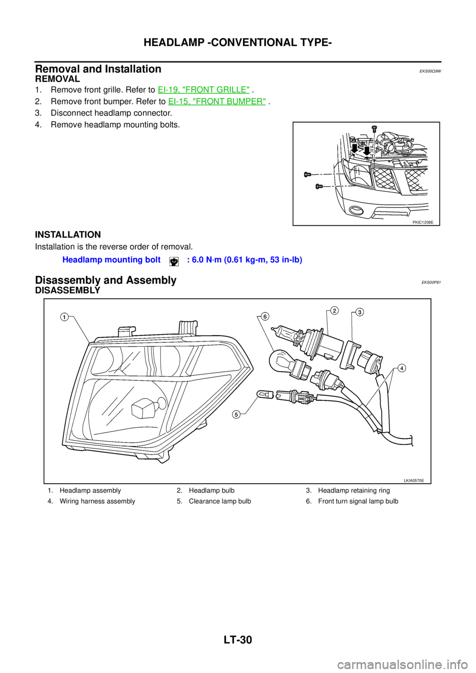
REMOVAL
1. Remove front grille. Refer toEI-19, "FRONT GRILLE".
2. Remove front bumper. Refer toEI-15, "
FRONT BUMPER".
3. Disconnect headlamp connector.
4. Remove headlamp mounting bolts.
INSTALLATION
Installation is the reverse order of removal.
Disassembly and AssemblyEKS00P81
DISASSEMBLY
PKIC1208E
Headlamp mounting bolt : 6.0 N·m (0.61 kg-m, 53 in-lb)
1. Headlamp assembly 2. Headlamp bulb 3. Headlamp retaining ring
4. Wiring harness assembly 5. Clearance lamp bulb 6. Front turn signal lamp bulb
LKIA0570E
Page 2114 of 3171
HEADLAMP - DAYTIME LIGHT SYSTEM -
LT-31
C
D
E
F
G
H
I
J
L
MA
B
LT
HEADLAMP - DAYTIME LIGHT SYSTEM -PFP:26010
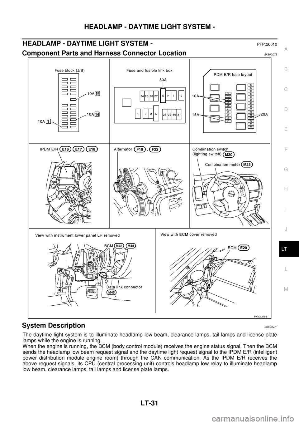
Component Parts and Harness Connector LocationEKS00Q7E
System DescriptionEKS00Q7F
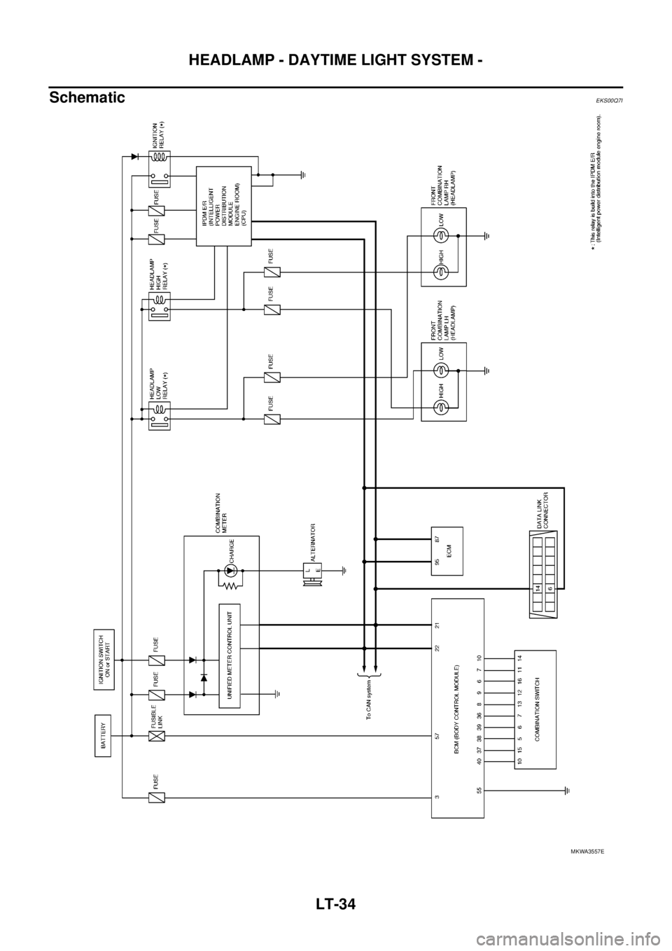
The daytime light system is to illuminate headlamp low beam, clearance lamps, tail lamps and license plate
lamps while the engine is running.
When the engine is running, the BCM (body control module) receives the engine status signal. Then the BCM
sends the headlamp low beam request signal and the daytime light request signal to the IPDM E/R (intelligent
power distribution module engine room) through the CAN communication. As the IPDM E/R receives the
above request signals, its CPU (central processing unit) controls headlamp low relay to illuminate headlamp
low beam, clearance lamps, tail lamps and license plate lamps.
PKIC1219E
Page 2115 of 3171

LT-32
HEADLAMP - DAYTIME LIGHT SYSTEM -
OUTLINE
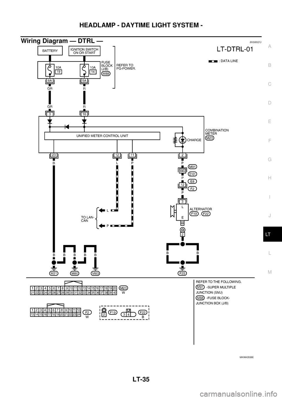
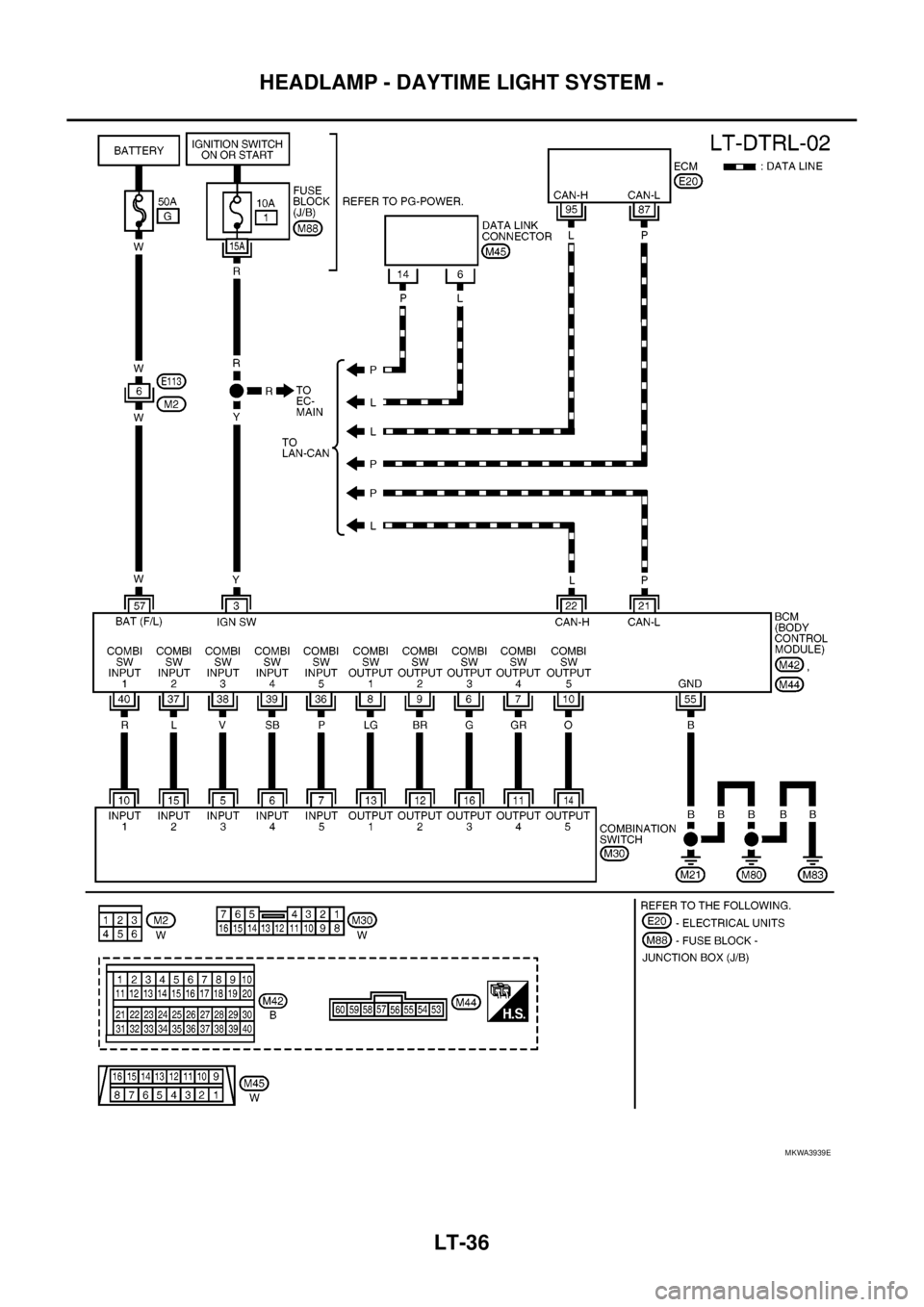
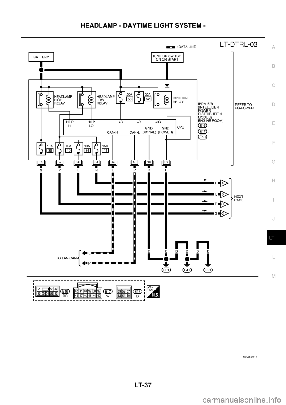
Power is supplied at all times
lto ignition relay (located in IPDM E/R)
lto headlamp high relay (located in IPDM E/R) and
lto headlamp low relay (located in IPDM E/R), from battery directly,
lthrough 50A fusible link (letter G, located in fuse and fusible link box)
lto BCM terminal 57,
lthrough 20A fuse (No. 52, located in IPDM E/R) and
lthrough 20A fuse (No. 53, located in IPDM E/R)
lto CPU (located in IPDM E/R),
lthrough 10A fuse [No. 19, located in fuse block (J/B)]
lto combination meter terminal 3.
With the ignition switch in the ON or START position, power is supplied
lto ignition relay (located in IPDM E/R),
lthrough 10A fuse [No. 1, located in fuse block (J/B)]
lto BCM terminal 3,
lthrough 10A fuse [No. 14, located in fuse block (J/B)]
lto combination meter terminal 16.
Ground is supplied at all times
lto BCM terminal 55 and
lto combination meter terminal 23
lthrough grounds M21, M80 and M83,
lto IPDM E/R terminals 38 and 59
lthrough grounds E21, E41 and E61.
DAYTIME LIGHT OPERATION
With the lighting switch in the OFF position and engine running, the BCM receives input signal requesting
headlamp low beam, clearance lamp, license plate lamp, and tail lamp to illuminate. This input signal is com-
municated to the IPDM E/R through the CAN communication. The CPU located in the IPDM E/R controls
headlamp low relay.
lthrough 15A fuse (No. 41, located in IPDM E/R)
lthrough IPDM E/R terminal 54
lto front combination lamp RH terminal 1,
lthrough 15A fuse (No. 40, located in IPDM E/R)
lthrough IPDM E/R terminal 52
lto front combination lamp LH terminal 1.
Ground is supplied at all times
lto front combination lamp RH and LH terminals 3
lthrough grounds E21, E41 and E61.
With power and ground supplied, the headlamp low beam, clearance, license plate and tail lamps illuminate.
Page 2116 of 3171
HEADLAMP - DAYTIME LIGHT SYSTEM -
LT-33
C
D
E
F
G
H
I
J
L
MA
B
LT
COMBINATION SWITCH READING FUNCTION
Refer toBCS-3, "COMBINATION SWITCH READING FUNCTION".
AUTO LIGHT OPERATION
Refer toLT-49, "System Description".
CAN Communication System DescriptionEKS00Q7G
Refer toLAN-23, "CAN COMMUNICATION".
CAN Communication UnitEKS00Q7H
Refer toLAN-30, "CAN Communication Unit".
Page 2117 of 3171
LT-34
HEADLAMP - DAYTIME LIGHT SYSTEM -
Schematic
EKS00Q7I
MKWA3557E
Page 2118 of 3171
HEADLAMP - DAYTIME LIGHT SYSTEM -
LT-35
C
D
E
F
G
H
I
J
L
MA
B
LT
Wiring Diagram — DTRL —EKS00Q7J
MKWA3558E
Page 2119 of 3171
LT-36
HEADLAMP - DAYTIME LIGHT SYSTEM -
MKWA3939E
Page 2120 of 3171
HEADLAMP - DAYTIME LIGHT SYSTEM -
LT-37
C
D
E
F
G
H
I
J
L
MA
B
LT
MKWA3321E
Trending: interior lights, alarm, water pump, gas type, transmission oil, load capacity, lumbar support


